MAVB3D
Posted by pugzor
Hi all,
I want to pick up my build which sort-of started maybe 18-24 months ago now. Long story short, I found a girl (we're getting married in September) but this is something I got a damn good start on and would like to finish.
Anyway, I've had a few printers starting with a home-made Cherry Pi IIIS delta. Was a silly way to get introduced to 3D printing and I really should have done something easier like a Prusa i3. Probably 8 hours building and 40 hours debugging! I did get it printing awesomely though so I'm confident to go back to something a little more conventional but scaled up. Also acquired a M3D Micro from Kickstarter, which is cool, but the lack of a heated bed really makes it pretty limited. Actually considering backing the Obsidian too when it goes up in the next few days but we'll see.
Here's how well I got my delta honed in:
Basically the idea for this was to build a massive volume 3D printer that could do its thing for days on end without supervision. I forget what the acronym for MAVB3D is, but it was cool at the time so I'm going to keep it as that for the project name.
Design is mostly built around those Vulcanus Max (CoreXY) printers that were floating around a few years ago. Admittedly they were the inspiration although I have deviated from the design a bit. [www.instructables.com] End goal is to have a print envelope of around 500x500x500mm with maybe a 50 micron print resolution.
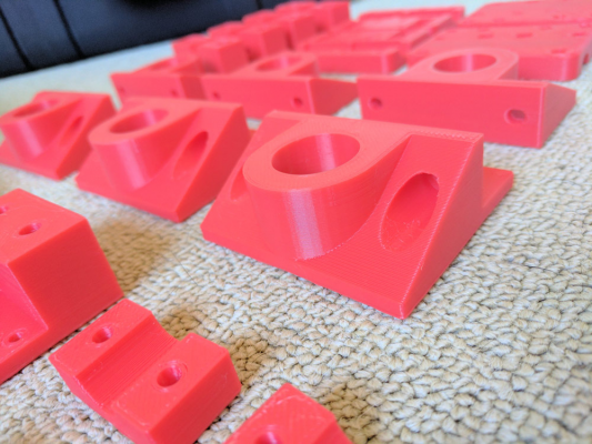
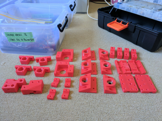
I printed most of the plastics required as per here:
Main thing I haven't printed yet is the extruder carriage as I want to go a bit custom with that. First iteration will be just a single direct drive (was considering Bowden for a while, but that's going to be unusable with the massive tubes required) and I'll try to make it dual-head one day. Hopefully I can use 23mm high NEMA17s to keep down the weight of this carriage. Although it's being made to support massive objects I'll be using standard 1.75mm filament with a 0.4mm nozzle - I do want good quality prints despite the size.
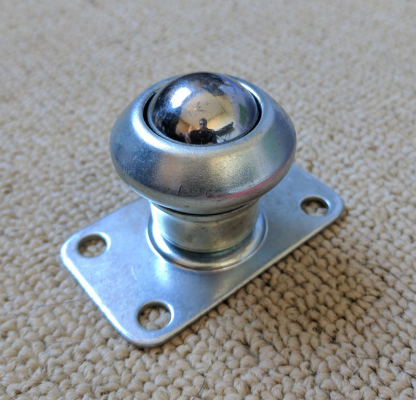
I figured taking a triangular approach to mounting the print bed was going to be the easiest way to scale this up. It'll be driven by a single NEMA23 as discussed in this topic: [forums.reprap.org]. The bed will have three leadscrews driving vertically (two on the sides, close to the front, and one at the rear in the centre) and four smooth rods at the four corners (on the sides). Lead screws will sit on these castor-type bearings that I found (can't remember their technical name):
Also made these nice little brackets to hold the leadscrews in place with standard 608 bearings:
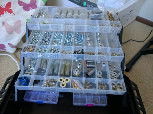
Main drive for the leadscrews should be 16 tooth at the motor and 40 tooth at the base of the rods. Got plenty of everything though:
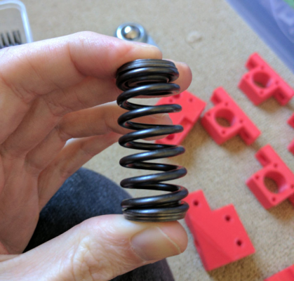
Hoping to manually adjust bed level, again using triangular technique, using valve springs from a 1998 Toyota Camry. Funnily enough they are brilliant for this application - they're made to withstand extreme heat, are made to have a large amount of pressure, and were absolutely free. Two of these will be on the back edge of the print bed (at either corner) with a third at the centre middle of the front edge. Once I hone these in I probably will never need to adjust them ever again.
I've got a nice big chunk of flatness-milled aluminium for the bed. It's 8mm thick if I recall and should have a flatness of 0.38mm over 6ft (again, if memory serves). Might throw a very thin piece of float glass over the top to protect the bed too. Bed is already ~10kg. Did get a nice big silicone mat to heat it up too which will stick on the bottom.
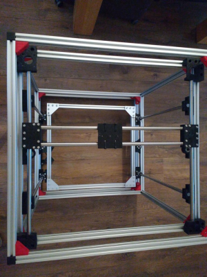
Already have built the frame. It's large! Base is 750x750mm on the outer and barely fits through doorways. It's mounted on some chipboard too for extra stability. Unlike the Vulcanus Max I used 20x40 pieces of rail to give it more rigidity in most areas, and my corner posts are 40x40mm. Should be bloody rigid.
For electronics I was going to go one of those cheap AliExpress MKS SBase boards (seriously, dat price!), but I've since decided I'll pay 10x more and go for a Duet WiFi + Duex5. Mostly made this decided this for the support factor (David and those involved are priceless) and less to troubleshoot without having to worry about the electronics being dodgy. Might go a PanelDue and IR Probe too but we'll see how money comes.
Decided to run the thing on 24v due to the amount of power needed. Ended up being more economical when it came to power supplies. Have a few other things I want it to handle (like LEDs) so may have a small 12v PSU to handle a few independent systems. We'll see how it goes though.
First thing I need to do is perform a stocktake, see what I really do and don't have, and figure out exactly how I'm going to execute some of the more creative bits and pieces. I'll hopefully make a post or two on here as things progress! No doubt there'll be requests for troubleshooting come through.
|
Re: MAVB3D June 25, 2017 12:01AM |
Registered: 11 years ago Posts: 5,780 |
"End goal is to have a print envelope of around 500x500x500mm with maybe a 50 micron print resolution....I printed most of the plastics required as per here: "
I'm not sure 500x500x500 mm, 50 um resolution, and printed plastic parts all belong in the same sentence, let alone the same printer. For that kind of size and resolution, rigidity in every component will be critical. Plastic part use, especially printed plastic parts, should be minimized.
If you have a flat aluminum bed you don't need to put glass on it. It's better to use a material like PEI that prints will stick to without slopping hairspray, glue, or root beer, on it.
Using four rails is asking for trouble. If there's even a tiny misalignment (and there will be) the whole thing will bind or walk instead of moving smoothly. You shouldn't need more than two rails, preferably located close to the screws. For the sort of resolution you're after, I wouldn't use end-supported rails, either. Use fully supported rails or linear guides.
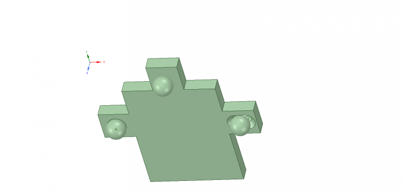
When you heat the 500 mm bed to 100C is is going to expand by almost 1 mm (about 0.5 mm when heated to 70C). Your bed support system may not be too happy about that, and you may have problems with the bed lifting or the bed or support structure flexing. I designed a three point support mechanism for my latest printer that allows the bed to expand without creating any lateral forces on the leveling screws. I support the bed from below using a rigid support structure in the form of a "tee" made from 40x40mm 8020 extrusion (probably overkill for my printer, but probably about right for yours). The bed plate sits on 3 screws, two of which have spherical heads. There is a reference screw that is typically not adjusted, whose spherical head sits in a conical hole in the bottom of the bed plate. The conical hole prevents any lateral motion at that location, but since the screw head is spherical, the bed can swivel on that screw when leveling. On the opposite side of the bed there is another spherical support screw, the pitch adjuster, but this one sits in a conical slot (made with a countersink bit on a mill). The slot allows the bed to expand in the X direction but prevents any motion in the Y direction. The spherical screw head allows the bed to pivot for leveling. The third screw, the roll adjuster, is simply a screw that contacts the flat bottom of the bed plate. That allows the bed to expand in X and Y and to pivot for leveling adjustments. At each of the three screws there are springs that hold the plate down onto the screws.
Here's the general idea, viewed from the bottom:
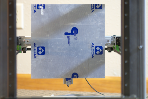
Here's what it looks like in practice (top view):
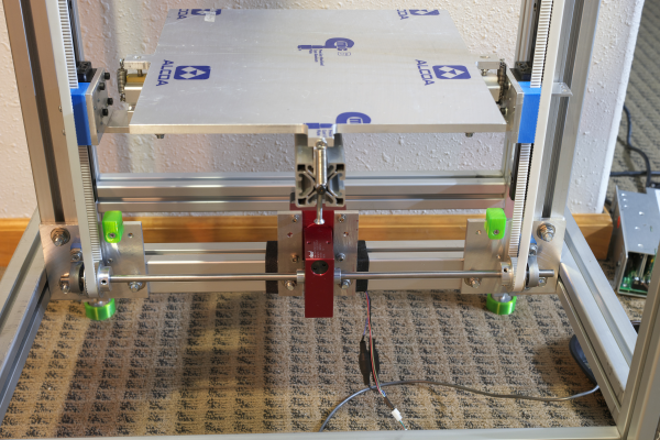
The screw on the left is the reference that sits in a conical hole. The screw on the right is the X axis pitch adjuster. The screw at the front center is the roll adjuster and has a thumbwheel under the assembly. The reference and pitch adjusters are spherical head screws used in RC cars. They have 2.5 mm hex sockets on the top so they are adjusted from the top side of the bed. All three screws are threaded into teflon or torlon blocks that don't mind the temperature and grip the screws tightly so the bed can't wobble.
You may find that with only 3 supports, a bed that size may sag under it's own weight and not provide the flatness you need to print in 50 um layers. You may have to do something a little more complex to support the corners on the side with the roll adjuster. This is a situation where autoleveling that maps the bed may be useful.
Setting aside the difficulty and expense of building a large printer with the sort of resolution you're after, have you considered how long it will take to print a large object in 50 um layers? You certainly can do it, but people usually match the printer size to the object size. Large printers usually print large objects in thick layers so they'll finish in a reasonable amount of time. Things that require very high resolution are usually small and usually printed on smaller printers that are much easier to build to the required rigidity and resolution. Just something to think about...
Ultra MegaMax Dominator 3D printer: [drmrehorst.blogspot.com]
|
Re: MAVB3D June 25, 2017 04:04AM |
Registered: 9 years ago Posts: 164 |
Really appreciate the time you took putting into that post Mark! I whole-heartedly agree with you on most of those points and the rest has definitely given me more to think about. Some clarifications:
In terms of plastic parts I've really limited it. At the moment it's brackets for the smooth rods (which won't have any force on them that they wouldn't have in a smaller scale) and the rest of the CoreXY drive setup. When it comes to anything that supports the bed I've used all metal brackets. Even when putting together the frame using V-slot I used only metal 90° brackets. Definitely one area I'm aware of - don't like using plastic parts when scaling up. Actually, I did 3D print some jigs for making metal brackets - made it much easier with these as drill guides.
Secondly, the 50 micron thing. Absolutely; there's no way that I'm practically going to be doing many large-scale prints at that resolution. I would like to try and aim to be able to do that though, even for small prints, just to say it's capable. To be honest I can't imagine myself practically printing smaller than 100um. Even then it's more about the filament you use, print speed, fan settings, etc, that will get you the results rather than doing thinner layers. Well, from what I've seen.
The glass bed topper was more around an issue I've heard of with large print beds, being that sometimes when heated they can form waves (especially when it's got a lot of mounting points, which I'm avoiding). I'm not a fan of printing on glass (currently do it with my delta, can be annoying) but it is generally very flat and does a good job of protecting anything underneath.
As for the rails, I'm not entirely sure what you mean. As per the Vulcanus Max series I was going to have 4x smooth rods as guides and use 3x leadscrews (similar to ideas in that other thread I linked) to drive vertical bed movement. Have I got my terminology wrong? Would definitely like to avoid issues with alignment and I know it's going to be challenging already to get the smooth rods to line up.
I'll put together a few pictures of what I'm thinking for the layout of my bed and post them up for evaluation. It's not a perfect solution but it's a combination of a few different methods I've seen around the place. Admittedly, I'm pretty worried about how thermal expansion will affect the print bed. Probably my greatest concern is how a large number of heating/cooling cycles will affect it - pretty much unavoidable unless using exotic materials.
|
Re: MAVB3D June 25, 2017 08:41AM |
Registered: 11 years ago Posts: 5,780 |
I don't think the heating and cooling of the bed to the temperatures used for 3D printing is going to cause any sort of permanent deformation. Using cast tooling plate should prevent things from getting wavy when heated, and the fact that it's aluminum means it is going to heat evenly. The real problem will be that whatever you put on the surface, glass or PEI plus adhesive tape, comes with no tolerance spec for thickness or flatness, so there's no way to know what you're going to end up with. At 500 mm you're getting to the size where you may have to worry about the bed plate drooping around its supports. I'm not a fan of band-aids, but a thick first layer will mask a lot of these problems.
3 lead screws is fine because it adds stability in the Z axis, but I wouldn't use 4 vertical guide rails for Z. One rail will allow motion in the vertical direction, but the bed could rotate around it. Adding a second rail prevents that rotation and limits motion to the Z axis. Adding a third rail (one near each screw) probably doesn't hurt much and may reduce the chance of Z wobble related to flex in the rails and imperfections (bends) in the lead screws. Adding a 4th rail doesn't improve anything and increases the chances of misalignment which will cause problems. It's difficult to align 2 widely spaced rails parallel to each other. The more rails you use, the harder it gets to get/keep them parallel. I wouldn't try to do 500 mm of travel with less than 12 mm diameter end supported rails. I would use fully supported rails or linear guides.
Ultra MegaMax Dominator 3D printer: [drmrehorst.blogspot.com]
|
Re: MAVB3D June 25, 2017 10:47PM |
Registered: 9 years ago Posts: 164 |
Again, really appreciate that advice Mark.
You're right and I don't think there's much way around the flatness issue. Even if you added bracing underneath (or had a thicker piece of plate, then milled out a lot of the meat to have cross-bracing), it's likely it'd heat unevenly and likely result in some kind of distortion.
Fully supported rails would be easy to add on in place of smooth rods. If there's negligible benefit of having more than two, I might stick with two on either side (at half length) of the bed. SBR16 (16mm) fully supported guides are readily available here so I'll go with those. I imagine it'd be ~AU$120 for two of those with decent quality SBR16UU bearings.
|
Re: MAVB3D June 26, 2017 07:04AM |
Registered: 11 years ago Posts: 5,780 |
I think support a large bed that sags under its own weight (or has unflat glass or PEI plus adhesive) could be handled by starting with the three point scheme I used that allows it to expand when heated, and then adding additional screws to support it from below. I think you'd have to add some small, flat pieces to the underside of the heater for the screws to contact, so that when the thing expands and contracts it can slide a little on the tips of those screws. Then when the whole thing is assembled, you'd have to put a dial gauge on the extruder carriage and start measuring and tweaking the screws. The problem with screws is the pitch of the screws is so rough compared to the required adjustment it would be tricky to make it all work right.
A large, unflat surface is the perfect use case for autoleveling that maps the bed.
Ultra MegaMax Dominator 3D printer: [drmrehorst.blogspot.com]
A large, unflat surface is the perfect use case for autoleveling that maps the bed.
Ultra MegaMax Dominator 3D printer: [drmrehorst.blogspot.com]
|
Re: MAVB3D June 26, 2017 02:52PM |
Registered: 7 years ago Posts: 270 |
|
Re: MAVB3D June 27, 2017 11:07PM |
Registered: 9 years ago Posts: 164 |
@Mark, I've been thinking pretty heavily about some of the things you've said, mostly around the rails. Originally I thought you were referring to how the Z axis moves but I'm now worried about the gantry (X&Y axes). Smooth rods were planned but I suspect these would be quite prone to sagging too over the ~750mm they need to cover.
Based on the layout I'd originally been working with, changing these to fully supported linear rails isn't going to be fun as it'll require a lot of the gantry parts to be redesigned. Eg, motor mounts, carriages, belt routing, etc. I don't mind doing that (some rework now will save frustration with crappy prints, resulting in needing to do it anyway!), but I wanted your opinion - should dual smooth rods be fine for the carriage which holds the extruder/s (keeping in mind it'll be direct drive)? The side rails I'm fine to convert to supported linear rails but I'm worried about the additional weight/space required for the cross-rails.
There are a few brackets and mounting plates which I'll just make using metal parts too, I think.
What method would you recommend for auto bed levelling too on a large printer? Not sure whether to go PEI (hard to get large enough sheets here) or something else, but won't go glass. Probably Kapton tape. Original specs called for an inductive sensor but given I'd be going a Duet WiFi + Duex5, is there a better option?
@newbob I have no idea to be honest about the speed but think it was conservative... maybe 0.4mm nozzle at 35mm/s? Could have been faster. Was using extremely cheap Flashforge filament too so very happy with the results. I'll have to start up the PC with S3D on it again and see what the settings were. Extruder was a e3d v6 clone which performed quite well. Originally had a jhead but never quite had much luck with it. Admittedly I've been quite impressed with a lot of the knock-off gear I've had.
|
Re: MAVB3D June 28, 2017 10:34AM |
Registered: 8 years ago Posts: 120 |
Pugzor, 750mm will almost surely be to long for smooth rods and bearings. If you're worried about price, I would suggest looking on Aliexpress. I bought MGN12 rails for my CoreXY build and it trned out to be cheaper than a comparable smooth rod setup. IMO the way they bolt onto the extrusions is amazing. Also, the dual smooth rods for the X axis should be OK, but I would definitely switch to rails on the Y axis.
Another nice thing about using Hiwin-type rails is that they can potentially increase your build volume. I'm in the process of rebuilding my printer (mostly metal @DigitalDentist) and merely placing the rails on top of the extrusions save 40mm or so on each side.
Another nice thing about using Hiwin-type rails is that they can potentially increase your build volume. I'm in the process of rebuilding my printer (mostly metal @DigitalDentist) and merely placing the rails on top of the extrusions save 40mm or so on each side.
|
Re: MAVB3D June 29, 2017 08:14AM |
Registered: 9 years ago Posts: 164 |
Thanks Matt!
Actually not too worried about price - would prefer it to take a little longer and buy quality parts than be frustrated with crap. Admittedly though, AliExpress has served me well and generally speaking I haven't had an issue with anything from there! Takes a bit of selection - finding stuff that isn't the cheapest but seems more legit.
Lots of investigation to do!
I'm now wondering what the best path might be to take with extruders. I've been reading about the Titan Aero as well as the Zesty Nimble. Titan Aero seems like a good idea but I'm wondering the best way to potentially mount two of them while getting them low enough.
Sorry, only registered users may post in this forum.
