CoreXY design flaw spotted, EdgeXY concept fixes it, comments and review of analysis appreciated
Posted by lkcl
|
CoreXY design flaw spotted, EdgeXY concept fixes it, comments and review of analysis appreciated July 25, 2017 10:14AM |
Registered: 8 years ago Posts: 776 |
hi, i was made aware of a design concept called EdgeXY just recently, and so did a design analysis comparing it to CoreXY:
[forums.reprap.org]
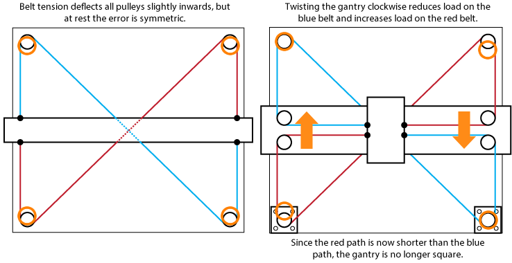
the conclusion: CoreXY has a design flaw, which only surfaces under very specific (combined) conditions: (a) high acceleration, (b) carriage is off-centre on the X-Gantry (left or right, but the further away from centre the greater the distortion) and (c) movement (with high acceleration) is in the Y-direction.
if we were to work out a formula for the amount of distortion it would be:
* let width of printer be called X
* let the position of the carriage on the X-gantry be Px
* let center point of X-gantry be Cx, equal to X/2
* let acceleration in Y direction be Ya
* let c be an arbitrary constant
* let the function absolute(X) be equal to X if X > 0 otherwise -X
then the amount of distortion would be:
* c times absolute(Px-Cx) times Ya
the design flaw stems from the fact that the X-Gantry is free to rotate, with only the mechanical strength of the rails/rods and the attachment of the X-Gantry to those rails/rods being the sole method of stopping any such potential rotation.
in the message referenced above i carry out an analysis which shows that the Edge-XY concept does *not* suffer from this critical flaw.
can anyone spot a mistake in either the Edge-XY analysis *or* the CoreXY analysis?
|
Re: CoreXY design flaw spotted, EdgeXY concept fixes it, comments and review of analysis appreciated July 25, 2017 11:47AM |
Registered: 8 years ago Posts: 5,232 |
|
Re: CoreXY design flaw spotted, EdgeXY concept fixes it, comments and review of analysis appreciated July 25, 2017 02:40PM |
Registered: 11 years ago Posts: 335 |
Quote
lkcl
The design flaw stems from the fact that the X-Gantry is free to rotate, with only the mechanical strength of the rails/rods and the attachment of the X-Gantry to those rails/rods being the sole method of stopping any such potential rotation.
[...]
Can anyone spot a mistake in either the Edge-XY analysis *or* the CoreXY analysis?
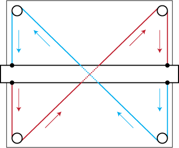
I haven't fully analyzed your posts, but the CoreXY design uses a crossed belt path to contstrain the grantry such that it is always square. Even if the motors are spinning freely, you cannot rotate the gantry because both the red and blue belt are of equal length.
In practice, the belts is often the only thing keeping the gantry square, because people use the rigidity CoreXY provides to get away with only a single block on the Y rails.
As far as I can tell your analysis of CoreXY is flawed because this principle holds even with the X carriage moving freely. (The red and blue belts are both rigidly connected across the carriage and the system is therefore equivalent.)
I am skeptical of your proposed design because any system with that many components is implicitly assuming that everything is perfectly rigid. In the real world every pulley, shaft, and linear bearing has compliance. If you design such that error accumulates at each step, it becomes almost impossible to build a rigid mechanism. A good pulley mount might deflect 20 microns under load, which is fine, but if you suddenly have 8 pulleys in the belt path then 8*20 becomes a material problem.
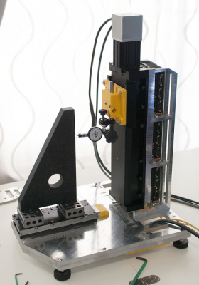
In everyday life we learn to accept that things made of metal and plastic are very rigid, but at the scale of a single FDM layer most components end up behaving like wet noodles. For example, this system weighs over fourty pounds as pictured and consists almost entirely of 1/2" aluminum plate, yet the Z axis will lean forward by ~30 microns when a realistic force is applied.
I have measured the performance of a number of positioning systems, and intuition tells me that relying on increasingly complicated belt paths to maintain gantry squareness is not an efficient design philosophy.
A second block for your linear rail might cost $3 from China.
|
Re: CoreXY design flaw spotted, EdgeXY concept fixes it, comments and review of analysis appreciated July 25, 2017 03:54PM |
Registered: 11 years ago Posts: 5,780 |
If you apply a sufficiently detailed analysis to any 3D printer mechanism I don't doubt that you'll be able to find nonideal conditions. But, they only matter if they result in print defects or limit other aspects of performance. Looking at the way printers work (and how most are built) and the considering the fact that we are squirting molten plastic out of a nozzle and lose all control of it the instant it leaves the nozzle, I can't help but feel like there are bigger, more obvious fish to fry.
I'll be much more interested if you can show me a print defect that can be attributed specifically to the flaw you've "discovered". Until then, it mostly looks like an argument to use fully supported linear guides instead of flexible end supported guide rails (but we already knew they were better), or maybe to turn down the acceleration a little. Meh.
Ultra MegaMax Dominator 3D printer: [drmrehorst.blogspot.com]
|
Re: CoreXY design flaw spotted, EdgeXY concept fixes it, comments and review of analysis appreciated July 26, 2017 07:27AM |
Registered: 8 years ago Posts: 776 |
Quote
691175002
I haven't fully analyzed your posts, but the CoreXY design uses a crossed belt path to contstrain the grantry such that it is always square. Even if the motors are spinning freely, you cannot rotate the gantry because both the red and blue belt are of equal length.
ah. ok. so, that diagram is actually very useful (because of the arrows). tell me: if you attempted to pull (or push) in the direction of the arrows.... yes you're right! take the blue for example, the blue arrow goes down on left but also goes down *on the right*. sooOoo.... in faaact.... this is exactly the same force-resisting properties as the EtchXY. ha. thank you for pointing that out

Quote
.
In practice, the belts is often the only thing keeping the gantry square, because people use the rigidity CoreXY provides to get away with only a single block on the Y rails.
As far as I can tell your analysis of CoreXY is flawed because this principle holds even with the X carriage moving freely. (The red and blue belts are both rigidly connected across the carriage and the system is therefore equivalent.)
yehyeh, which... as long as you're happy with relying on the belts' structural properties that's fine

Quote
I am skeptical of your proposed design
... it's not mine, i am currently analysing it. analysed it (with help from a newcomer to this forum, named benson) - benson spotted a flaw in my EtchXY analysis, which is that the entire assembly (green and yellow blocks) can actually rotate freely without constraint. this is... baaad
 so i will not be using it.
Quote
because any system with that many components is implicitly assuming that everything is perfectly rigid. In the real world every pulley, shaft, and linear bearing has compliance. If you design such that error accumulates at each step, it becomes almost impossible to build a rigid mechanism. A good pulley mount might deflect 20 microns under load, which is fine, but if you suddenly have 8 pulleys in the belt path then 8*20 becomes a material problem.
that's a really valuable assessment, really appreciated.
Quote
In everyday life we learn to accept that things made of metal and plastic are very rigid, but at the scale of a single FDM layer most components end up behaving like wet noodles. For example, this system weighs over fourty pounds as pictured and consists almost entirely of 1/2" aluminum plate, yet the Z axis will lean forward by ~30 microns when a realistic force is applied.
yowch!
Quote
I have measured the performance of a number of positioning systems, and intuition tells me that relying on increasingly complicated belt paths to maintain gantry squareness is not an efficient design philosophy.
yyeahh i think i learned that one, with the riki200 initial plotter experiment. so i decided to go pretty simple instead.
Quote
A second block for your linear rail might cost $3 from China.
luckily i'm in taiwan then, eh?

thanks 691175002. really appreciate your insight and expertise in helping me from making huge mistakes.
|
Re: CoreXY design flaw spotted, EdgeXY concept fixes it, comments and review of analysis appreciated July 26, 2017 07:29AM |
Registered: 8 years ago Posts: 776 |
Quote
o_lampe
There might be a small distortion of the x-gantry around the z-axis, but the further away from the center the carriage is, the shorter is the lever of this distortion.
turns out that 691175002 showed me, the assessment i made of CoreXY is wrong, it won't rotate freely: a clockwise pull is resisted by one (or other) of the belts in the anti-clockwise direction. i should have suspected this, because engineers who created those drafting tables (on which CoreXY is based) would, if you think about it, not have made such a basic design mistake....

|
Re: CoreXY design flaw spotted, EdgeXY concept fixes it, comments and review of analysis appreciated July 26, 2017 07:33AM |
Registered: 8 years ago Posts: 776 |
Quote
the_digital_dentist
If you apply a sufficiently detailed analysis to any 3D printer mechanism I don't doubt that you'll be able to find nonideal conditions. But, they only matter if they result in print defects or limit other aspects of performance. Looking at the way printers work (and how most are built) and the considering the fact that we are squirting molten plastic out of a nozzle and lose all control of it the instant it leaves the nozzle, I can't help but feel like there are bigger, more obvious fish to fry.
haha yeah good point. nophead tried a few years ago to correct errors made when you make increasingly-small circles: the filament drags "inwards" at a rate that's inversely proportional to the diameter of the circle you're trying to make.... he worked out a formula to correct it
Quote
I'll be much more interested if you can show me a print defect that can be attributed specifically to the flaw you've "discovered". Until then, it mostly looks like an argument to use fully supported linear guides instead of flexible end supported guide rails (but we already knew they were better), or maybe to turn down the acceleration a little. Meh.
aww i _like_ pushing things a little. yehno 691175002 kindly pointed out that the analysis was flawed. it happens.
|
Re: CoreXY design flaw spotted, EdgeXY concept fixes it, comments and review of analysis appreciated July 26, 2017 08:20AM |
Registered: 8 years ago Posts: 601 |
Quote
691175002
I am skeptical of your proposed design because any system with that many components is implicitly assuming that everything is perfectly rigid. In the real world every pulley, shaft, and linear bearing has compliance. If you design such that error accumulates at each step, it becomes almost impossible to build a rigid mechanism. A good pulley mount might deflect 20 microns under load, which is fine, but if you suddenly have 8 pulleys in the belt path then 8*20 becomes a material problem.
I do understand this, but is it a problem? Surely each pulley will only deflect by x amount (lets say 20 microns) in a certain direction due to the tension in the belt system. It will not move in the other direction and so won't add positional errors. It may cause the belt to slowly ride up the pulley (depending on how they are mounted, preferably on both sides to avoid this. If the pulley is mounted perfectly then it won't ride up the pulley, the top and bottom will deflect equally although this is unlikely.) and this will in turn cause some slight misalignment of the belt and perhaps a small positioning error that increases with greater distance of the gantry.
Is this positioning error noticeable? If I make a series of cubes increasing in size, will the last cube be a fraction smaller? If it does, surely the value will be repeatable and correctable in firmware?
Edited 1 time(s). Last edit at 07/26/2017 08:20AM by Origamib.
|
Re: CoreXY design flaw spotted, EdgeXY concept fixes it, comments and review of analysis appreciated July 26, 2017 11:05AM |
Registered: 11 years ago Posts: 335 |
Quote
I do understand this, but is it a problem? Surely each pulley will only deflect by x amount (lets say 20 microns) in a certain direction due to the tension in the belt system. It will not move in the other direction and so won't add positional errors.
If you assume the system is under tension to begin with the pulleys will be at some intermediate level of deflection at rest, and will therefore be able to move in the opposite direction.
In essence, the CoreXY system places responsibility for gantry squareness on the pulleys and timing belt instead of the linear bearings. This is often a favourable trade, because pulleys are lighter and more compact than additional linear bearings.
When analyzing the system it is easy to assume that timing belt stretch is the weak link, but certain arrangements (a skate bearing supported by an M4 socket cap screwed into printed plastic) are probably going to be more compliant than the belt, especially with 8-16 of them in the design.
Note that cumulative error is going to be smaller than the sum of the individual errors depending on the shape of the belt path. In practice the final deflection at the nozzle might end up being 2-4x the deflection of a single pulley (I haven't measured this so I have no idea).
PS. I don't want to imply that pulleys alone can make-or-break the printer, many other design choices have similar impact. You should view every piece of the printer as a potential source of error, including the frame, motor mounts, shaft couplings, linear bearings... No single decision is critical when viewed in isolation, but if you get sloppy in too many places it adds up.
|
Re: CoreXY design flaw spotted, EdgeXY concept fixes it, comments and review of analysis appreciated July 26, 2017 04:53PM |
Registered: 8 years ago Posts: 601 |
Quote
691175002
Quote
I do understand this, but is it a problem? Surely each pulley will only deflect by x amount (lets say 20 microns) in a certain direction due to the tension in the belt system. It will not move in the other direction and so won't add positional errors.
If you assume the system is under tension to begin with the pulleys will be at some intermediate level of deflection at rest, and will therefore be able to move in the opposite direction.
In essence, the CoreXY system places responsibility for gantry squareness on the pulleys and timing belt instead of the linear bearings. This is often a favourable trade, because pulleys are lighter and more compact than additional linear bearings.
When analysing the system it is easy to assume that timing belt stretch is the weak link, but certain arrangements (a skate bearing supported by an M4 socket cap screwed into printed plastic) are probably going to be more compliant than the belt, especially with 8-16 of them in the design.
Note that cumulative error is going to be smaller than the sum of the individual errors depending on the shape of the belt path. In practice the final deflection at the nozzle might end up being 2-4x the deflection of a single pulley (I haven't measured this so I have no idea).
PS. I don't want to imply that pulleys alone can make-or-break the printer, many other design choices have similar impact. You should view every piece of the printer as a potential source of error, including the frame, motor mounts, shaft couplings, linear bearings... No single decision is critical when viewed in isolation, but if you get sloppy in too many places it adds up.
EDIT: Scratch that I'm having a derp moment. You are correct that the pulleys will add more deflection but this depends on how much force the pulleys + mounts can take, and how much weight is going to be flung around. If we assume properly mounted pulleys on shoulder bolts through 5mm aluminium plate, then this might not be that significant seeing as a coreXY gantry might only be about 1kg +/- few hundred grams.
As usual though this needs some experimental evidence... Would a similar CoreXY and a standard Cartesian machine have similar amounts of deflection?
Edited 2 time(s). Last edit at 07/26/2017 08:06PM by Origamib.
|
Re: CoreXY design flaw spotted, EdgeXY concept fixes it, comments and review of analysis appreciated July 27, 2017 01:54AM |
Registered: 7 years ago Posts: 249 |
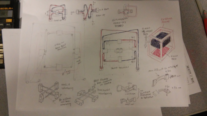
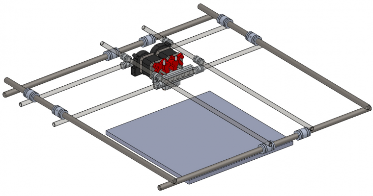
Interestingly enough, the above pic of my sketch is from July 2016, as are the Solidworks files. Calling it "CorelessXY" for lack of a better name.
At that time had done the finite element analysis for deflection (modulus of elasticity) for various configurations.
Frame, pulleys and belts were not considered relevant, as those variables are present in any build.
Looking for a valid structure, relative to rod size and placement to cover a 300x300 build plate with dual Flexion direct drive extruders (heavy), ended up with the hash (pound if you're English) beam layout identical to lkcl's Riki200.
Comparing additional mass to rigidity, the hash beam was the most weight saving solution over normal twin beam arrangements found in most printers.
Driving the hash by coreXY was more of a "what if", as the kinematics had impressed me. To me it seems simple, to others "overly complicated".
As stated in the other thread, it's a unique configuration. Can it be done differently, sure. But that's the beauty of RepRap, to share something new.
|
Re: CoreXY design flaw spotted, EdgeXY concept fixes it, comments and review of analysis appreciated July 27, 2017 04:24PM |
Registered: 8 years ago Posts: 1,671 |
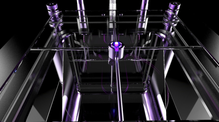
I did a design a while back(2014) called Zmap Ultra, (before I even knew the Core XY was a thing)
more related to etch a sketch in the way it dirves the XY rods, similar to above image.
more related to etch a sketch in the way it dirves the XY rods, similar to above image.
|
Re: CoreXY design flaw spotted, EdgeXY concept fixes it, comments and review of analysis appreciated July 27, 2017 05:40PM |
Registered: 11 years ago Posts: 335 |
Quote
Origamib
As usual though this needs some experimental evidence... Would a similar CoreXY and a standard Cartesian machine have similar amounts of deflection?
It depends too much on implementation, even saying the machines are similar leaves a lot open to interpretation. The only real constant is that CoreXY will have better acceleration because the gantry can be lighter and does not need to carry a motor.
As the build gets heavier and more expensive, the performance of a CoreXY will eventually be limited by the belt. A general cartesian robot has no such constraint and can switch to ballscrew, rack and pinion, or other systems such as [www.youtube.com] .
Quote
If we assume properly mounted pulleys on shoulder bolts through 5mm aluminium plate, then this might not be that significant seeing as a coreXY gantry might only be about 1kg +/- few hundred grams.
To discuss rigidity at the margin we need to decide what degree of repeatability and accuracy are necessary to produce "perfect" prints.
Absolute accuracy is mostly irrelevant because nobody cares if a 100mm command becomes 100.2mm at the extruder. On the other hand, repeatability is very important because a random error of +-0.2mm in consecutive layers will produce an awful surface finish. Humans are staggeringly good at detecting surface finish variation.
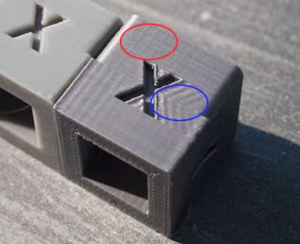
I like to divide printing artifacts into two categories. The first set of artifacts are caused by acceleration, which are the largest in magnitude but are consistant across layers. I've circled an example of this kind of error in blue.
The second type of error is purely random and is always present (circled in red). You will note that it is much smaller in magnitude than the previous error, but since it is fully random it is still quite noticable. My ballpark guess is that improvements in repeatability become imperceptible (or at least get overpowered by filament diameter variation) at +-20-50 microns. (The average diameter of human hair is 80 microns for comparison.)
If you try to sum the compliance of every single component connecting the print bed to the extruder nozzle, hitting <50 micron repeatability seems nearly impossible. The saving grace for most 3d printers is that the primary force acting on the carriage (acceleration) repeats across layers so in most cases you end up with ringing or corner blobs instead of roughness. This type of consistant error is much harder to identify by eye or touch, and might only become perceptible at ~200 microns or more.
Most people solve the "big" acceleration-induced artifacts by reducing carriage weight and tuning speed/accel/jerk, but residual error is just as annoying and is much harder to eliminate. The primary sources of residual error are most likely inaccuracy or roughness in the linear bearings along with forces exerted by the filament, bowden tube, and hot end wiring. Residual error can be reduced by improving overall rigidity and motion quality (by using longer linear blocks or spacing pairs of blocks further apart), but this will almost always make the printer heavier.
In this framework certain types of error are much worse than others, and otherwise inconspicuous decisions have implications for print quality - for example if your hot end hangs too far below the gantry it will act like a lever and magnify noise. For this reason you generally want every axis to be compact and driven at its center of gravity.
I haven't really answered your question, but my general view is that existing builds have not reached the physical limit of FDM print quality. If you can shave 50 microns of error from your build it will probably produce prints that are noticably better when compared side-by-side. Whether or not that improvement in print quality is worth the incremental cost is another matter entirely.
|
Re: CoreXY design flaw spotted, EdgeXY concept fixes it, comments and review of analysis appreciated August 01, 2017 04:26AM |
Registered: 9 years ago Posts: 383 |
Interesting thread. Considering re-building my Ormerod 2 to a core x-y style machine to increase build area and this thread has allowed me to avoid a few rookie mistakes!
I've seen many efforts to address accuracy or build rates of AM machines by targeting single measures, and often not following through the work to show the effects the developments would have for the end user. As a community do we have agreed benchmarks for surface finish, build rate, consistency, accuracy, etc? These are often difficult to truly assess as they will be in part reliant on part size and geometry.
While efforts are being made to achieve a 50 micron positional accuracy what efforts are being made to control the temperature of the machine, specifically the frame? Are you just choosing low thermal expansion rails - eg; Invar? If your frame is thermally uncontrolled/unmonitored aluminium extrusions then working on a positional accuracy of 50 micron begins to appear a waste of effort. Thermal expansion of aluminium from wikipedia is 23.1 microns per degree kelvin, per meter of length. So, for a 250mm piece to move 5 microns you are only talking of a temperature change of 0.86 centigrade, or 8.6 for the full 50 micron positional accuracy target.
Edit: Invar is very expensive! Having hunted around a bit if I get the go ahead to convert my Ormerod (work based project) I think I'd look into the cost of CNC cut cabon fibre sheet. This has low thermal conduction, low expansion, and high rigidity. Being epoxy based it wouldn't be so good too close to the hot bits though! ;-)
Edited 3 time(s). Last edit at 08/01/2017 04:57AM by WesBrooks.
|
Re: CoreXY design flaw spotted, EdgeXY concept fixes it, comments and review of analysis appreciated August 01, 2017 07:39AM |
Registered: 11 years ago Posts: 5,780 |
If you're really concerned about thermal effects you design the mechanism to allow them to happen and you start printing only after the machine's temperature has stabilized.
My latest printer's bed is on a kinematic mount that allows it to expand without creating lateral forces on the leveling screws that might cause the bed to lift or tilt or bow. The X axis guide rail uses a bearing block to attach it to one of the Y axis bearing blocks, so that when the frame expands and the Y axis guide rails move apart, the X axis rail can slide without creating large side loads that might cause the Y axis to bind.
OTOH, we are squirting molten plastic out of a nozzle and the plastic does what gravity and momentum tell it to do until it hardens enough that it can't. Also, filament diameter varies along its length, so the line width extruded will vary because the firmware assumes a constant filament diameter. We print from STL files that are approximations of the native CAD geometry. How accurate/precise can it get?
Ultra MegaMax Dominator 3D printer: [drmrehorst.blogspot.com]
|
Re: CoreXY design flaw spotted, EdgeXY concept fixes it, comments and review of analysis appreciated August 04, 2017 08:25PM |
Registered: 8 years ago Posts: 1 |
Quote
the_digital_dentist
The X axis guide rail uses a bearing block to attach it to one of the Y axis bearing blocks, so that when the frame expands and the Y axis guide rails move apart, the X axis rail can slide without creating large side loads that might cause the Y axis to bind.
I had a question regarding this, I've been following your build for a while (and I may have missed this, apologies if you've already spoken about it), when I read about your implementation of this sliding guide, you were concerned about it potentially introducing ringing. Now you have the printer up and printing, is this an issue? Or is this a good approach to deal with thermal expansion.
I'm currently stuck in a state of analysis paralysis designing my machine. I'm a CNC Machinist, and access to the tools and materials to build a high quality machine is quite achievable to me, but the sheer number of design problems, and solutions offered to them makes it hard to narrow things down. I had considered using a length of 15mm SHS Steel, 1.6mm wall thickness as a support for the X axis (And allowing me to use MGN9 without any flex in the rail over the length). If it is heated to 660C, then allowed to cool slowely, before taking very small passes alternating either side to bring it parallel it would give me a rail support with the same thermal expansion as the steel/iron base I would make for the Y Axis.
But then, if the bearing block attached to the Y Axis as a sliding support works, then KISS comes into play.
|
Re: CoreXY design flaw spotted, EdgeXY concept fixes it, comments and review of analysis appreciated August 05, 2017 03:07PM |
Registered: 8 years ago Posts: 776 |
Quote
the_digital_dentist
OTOH, we are squirting molten plastic out of a nozzle and the plastic does what gravity and momentum tell it to do until it hardens enough that it can't.
e3d just posted about their 0.15mm nozzles... they get better accuracy than FDM...
Quote
Also, filament diameter varies along its length, so the line width extruded will vary because the firmware assumes a constant filament diameter.
just investigated that today: apparently there's optical and mechanical sensors for measuring filament diameter. and in the "real" world (proper mechanical engineering world) there's laaaaserrrrrs [1] that can even measure if things are round or oval. [laserlinc.com]
Quote
We print from STL files that are approximations of the native CAD geometry. How accurate/precise can it get?
true!

[1] mythbusters: "We're making popcorn with laaaserrrrrs...." [www.youtube.com]
|
Re: CoreXY design flaw spotted, EdgeXY concept fixes it, comments and review of analysis appreciated August 05, 2017 03:29PM |
Registered: 11 years ago Posts: 5,780 |
The reason I put it the extra bearing block on the X axis was to prevent the mechanism from binding when the frame heats up, expands, and the Y axis rails move apart. I've only done a few prints with ABS, but the X axis arrangement has worked well. The mechanism runs as easily and smoothly at 50C as it does at 20C. I was not really concerned about ringing so much as poor layer registration due to there being one more set of bearings, possibly allowing some slop in the motion system. I can find no flaws in the prints that I would attribute to anything related to the bearing block on the X axis rail. Layer registration, as evidenced by sharp corners of prints, is near perfect.
Before the extra bearing block idea came to me, I toyed with the idea of making the XY base plate from a single piece of sheet steel. I eventually decided against it because of the weight and the difficulty in fabrication. A steel frame would expand less than aluminum, and would probably closely match the expansion of the X axis guide rail, so the extra bearing block in the X axis wouldn't be needed.
Very few corexy printers are enclosed to print ABS, so most people will never run into a thermal expansion problem. Even if they were enclosed, most use end supported rails, and if the frame expands and the Y axis rails move apart, they'll flex a little so again, probably no problem, unless printing a very large object that sends the X axis rail to the extreme ends of the Y axis.
Ultra MegaMax Dominator 3D printer: [drmrehorst.blogspot.com]
Sorry, only registered users may post in this forum.
