|
Z motor noise from binding... how do you align? December 01, 2017 07:03AM |
Registered: 7 years ago Posts: 128 |
|
Re: Z motor noise from binding... how do you align? December 01, 2017 11:08AM |
Registered: 11 years ago Posts: 5,780 |
The usual way is to align the moving parts without the screw(s) in place first- put the moving part at the bottom end of motion and tighten down the guide rails at that end, then move to the top of motion and tighten that end. Maybe go back and forth a couple times to make sure things are lined up properly, then add the screw(s) to the mix. Of course, the mounts for the guide rails have to be designed to allow adjustment, something that few people include in their designs.
Ultra MegaMax Dominator 3D printer: [drmrehorst.blogspot.com]
Ultra MegaMax Dominator 3D printer: [drmrehorst.blogspot.com]
|
Re: Z motor noise from binding... how do you align? December 02, 2017 02:38AM |
Registered: 8 years ago Posts: 5,232 |
I've also noticed, that temperature is sometimes a factor. I've built my CoreXY in a warm and cosy room, then moved the printer to the unheated workshop. 10°C less and I got binding. Same goes for enclosed printers.
You should adjust the rails at nearly target working temperature. And of course the frame has to be true and angled perfectly before you start aligning the rails/rods.
You should adjust the rails at nearly target working temperature. And of course the frame has to be true and angled perfectly before you start aligning the rails/rods.
|
Re: Z motor noise from binding... how do you align? December 02, 2017 07:57AM |
Registered: 11 years ago Posts: 5,780 |
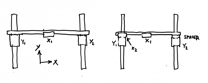
I anticipated the potential for thermal issues in UMMD and used an extra bearing block on the X axis.
Typical construction on the left, UMMD's on the right. In the typical construction, the Y axis rails are bolted to an aluminum frame and the X axis guide rail is solidly attached to the Y axis bearing blocks. When the frame expands and contracts, the Y axis rails move further apart and closer together a fraction of a mm. The steel X axis guide rail doesn't expand or contract as much as the aluminum frame and the result is large side loads on the Y axis bearing blocks. In the UMMD design, the X axis rail is firmly attached to the Y2 bearing block on the right (through a spacer), and on the left, the X2 bearing block is attached to the Y1 block. The X axis rail can move in the X2 block, but only in the X direction. As the Y axis rails move apart, the X axis rail just slides along with them in the X2 bearing block.
I have operated UMMD over a temperature range of about 10-50C and not had any problems.
Edited 1 time(s). Last edit at 12/02/2017 08:00AM by the_digital_dentist.
Ultra MegaMax Dominator 3D printer: [drmrehorst.blogspot.com]
|
Re: Z motor noise from binding... how do you align? December 02, 2017 09:00AM |
Registered: 6 years ago Posts: 1,007 |
The vast majority of these 3D printers are made (designed is not a proper term) without any consideration for proper constrain, alignment, rigidity ... and of course (a result in fact) thermal expansion.
Luckily, the way the guides are usually mounted is flexible (tie wrap) and the frame itself is flexible too, therefore binding is usually limited.
In your case, either it is worse than average or you use quality linear rail, ball screws that are even more demanding in term of proper mounting or Igus bearings (even more demanding contrary to what one would think).
There is not one magic solution to cure this as all depend on how your machine is made. Could be simple if the base is sound.
To get an idea, just look at the very few decent machines found here as shown above.
So without picture and description, not much to add.
"A comical prototype doesn't mean a dumb idea is possible" (Thunderf00t)
|
Re: Z motor noise from binding... how do you align? December 03, 2017 07:13AM |
Registered: 7 years ago Posts: 128 |
Thanks for the reply's.
So most of this issue is related at room temperature and I'm guessing the design has some impact on it as well.
I'm thinking at some point this is going to need a redesign...
ampapa,
So most of this issue is related at room temperature and I'm guessing the design has some impact on it as well.
I'm thinking at some point this is going to need a redesign...
ampapa,
|
Re: Z motor noise from binding... how do you align? December 03, 2017 11:31AM |
Registered: 11 years ago Posts: 5,780 |
How is that horizontal bar between the two Z bearing blocks attached to the blocks? Your Z axis is critically dependent on the parallelism of the two vertical frame members to which the Z axis guide rails are attached. How did you ensure that those were parallel? Linear guides are great bearings, but very unforgiving of misalignment. I cringe when I see printed plastic parts in what should be an accurate and precise mechanism.
Linear guides are easy to make parallel if you start with them in the same plane. You have them mounted on two different planes that you are hoping are parallel. If the linear guides were moved 90 degrees to the inside faces of the frame members, then connected together with single long bar I think you'd have a better chance of getting them parallel. You can assemble the back frame rectangle and know it's flat by assembling it with the pieces laying on a flat surface. When you bolt the guides to that you know they are in the same plane. Then the adjustment to parallel within that plane is easy by moving the carriage from one end of the axis to the other as you tighten down the linear guide mounting screws.
I think putting the motor/screws inside the rear frame rectangle will keep the screws close to the bearing blocks and reduce the whole bed assembly's tendency to pivot on the screws.
Assuming you did all that, you're now looking at a cantilevered bed with only the single bearing block on each linear guide subjected to all the torque that the cantilever produces, which may cause excessive wear or even binding. The free edge of a cantilevered bed will tend to bounce because of shaking in the machine, especially as the Y axis moves. There are two ways to fix that. Add a third screw at the free end of the bed, or move the two guide rails and screws to the center of the bed to balance the load.
I am getting excellent print quality from the two-belt-lifted Z axis in my coreXY printer. There no detectable bounce and no print artifacts that are normally attributed to cantilever bounce.
Ultra MegaMax Dominator 3D printer: [drmrehorst.blogspot.com]
|
Re: Z motor noise from binding... how do you align? December 05, 2017 07:18AM |
Registered: 7 years ago Posts: 128 |
They are mounted with a couple of aluminum spacers that I milled up.
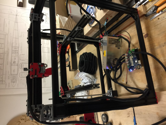
When assembling, both linear rails were loose on the face of the rail and tightened at the bottom when the bearing block was positioned there and at the top similarly. When the alignment was complete the vertical movement had relatively smooth action. This seems to be less a problem than the positioning of the motors and rods as positioning them exactly where they balance the Z axis seems almost impossible..
Most of the frame is doubled up with 90 degree aluminum corners so its very rigid. I also didn't think the 3D parts were enough to support a cantilevered bed and for that matter the strength needed for the entire frame.
This is going to need to be re-engineered for sure. I really don't like the movement of the axis on the 2 linear rods it just seems like binding is going to be a problem...
I've read through your thread, excellent build, can you point me to your page with the Z axis movement and the three point setup?
Thanks for the feedback,
When assembling, both linear rails were loose on the face of the rail and tightened at the bottom when the bearing block was positioned there and at the top similarly. When the alignment was complete the vertical movement had relatively smooth action. This seems to be less a problem than the positioning of the motors and rods as positioning them exactly where they balance the Z axis seems almost impossible..
Most of the frame is doubled up with 90 degree aluminum corners so its very rigid. I also didn't think the 3D parts were enough to support a cantilevered bed and for that matter the strength needed for the entire frame.
Quote
Digital Dentist
Linear guides are easy to make parallel if you start with them in the same plane. You have them mounted on two different planes that you are hoping are parallel. If the linear guides were moved 90 degrees to the inside faces of the frame members, then connected together with single long bar I think you'd have a better chance of getting them parallel. You can assemble the back frame rectangle and know it's flat by assembling it with the pieces laying on a flat surface. When you bolt the guides to that you know they are in the same plane. Then the adjustment to parallel within that plane is easy by moving the carriage from one end of the axis to the other as you tighten down the linear guide mounting screws.
I think putting the motor/screws inside the rear frame rectangle will keep the screws close to the bearing blocks and reduce the whole bed assembly's tendency to pivot on the screws.
This is going to need to be re-engineered for sure. I really don't like the movement of the axis on the 2 linear rods it just seems like binding is going to be a problem...
Quote
Digital Dentist
Assuming you did all that, you're now looking at a cantilevered bed with only the single bearing block on each linear guide subjected to all the torque that the cantilever produces, which may cause excessive wear or even binding. The free edge of a cantilevered bed will tend to bounce because of shaking in the machine, especially as the Y axis moves. There are two ways to fix that. Add a third screw at the free end of the bed, or move the two guide rails and screws to the center of the bed to balance the load.
I've read through your thread, excellent build, can you point me to your page with the Z axis movement and the three point setup?
Thanks for the feedback,
|
Re: Z motor noise from binding... how do you align? December 05, 2017 07:45AM |
Registered: 11 years ago Posts: 5,780 |
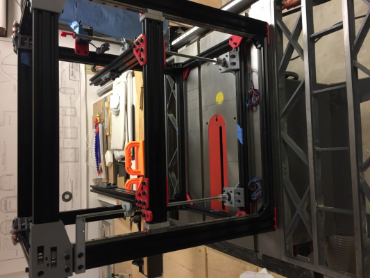
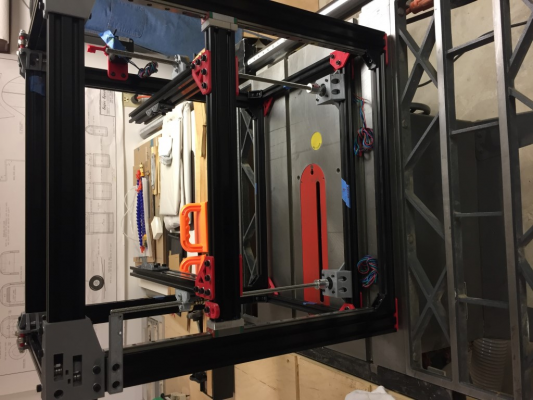
Here's the final Z axis design. I mounted the linear guides on the inside as you did but had no alignment problems so I left them that way. If I were to redesign it I might move them...
I don't know what sort of t-slot extrusion you used, but the stuff I used has a concave face which doesn't provide a flat surface to mount the linear guide. I milled some 0.25 mm deep slot into the t-slot to provide a flat place for the linear guide to sit.
Edited 1 time(s). Last edit at 12/05/2017 07:47AM by the_digital_dentist.
Ultra MegaMax Dominator 3D printer: [drmrehorst.blogspot.com]
Sorry, only registered users may post in this forum.
