Cyclonit's CoreXY
Posted by Cyclonit
|
Cyclonit's CoreXY December 06, 2017 04:26PM |
Registered: 8 years ago Posts: 13 |
Hi!
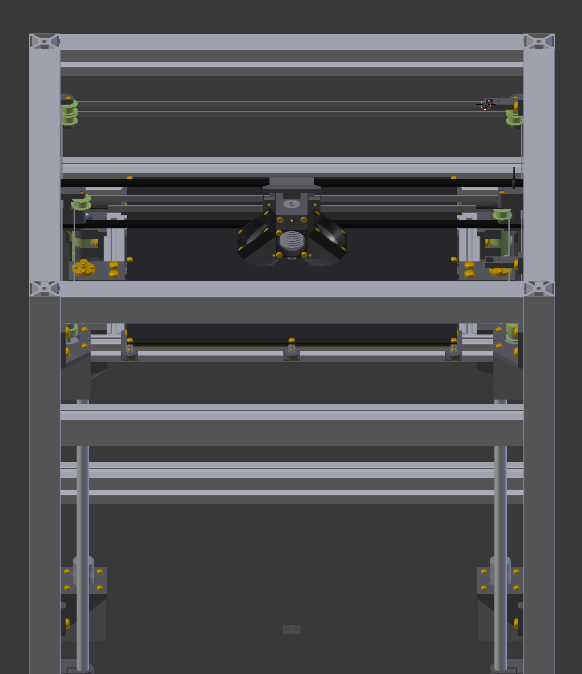
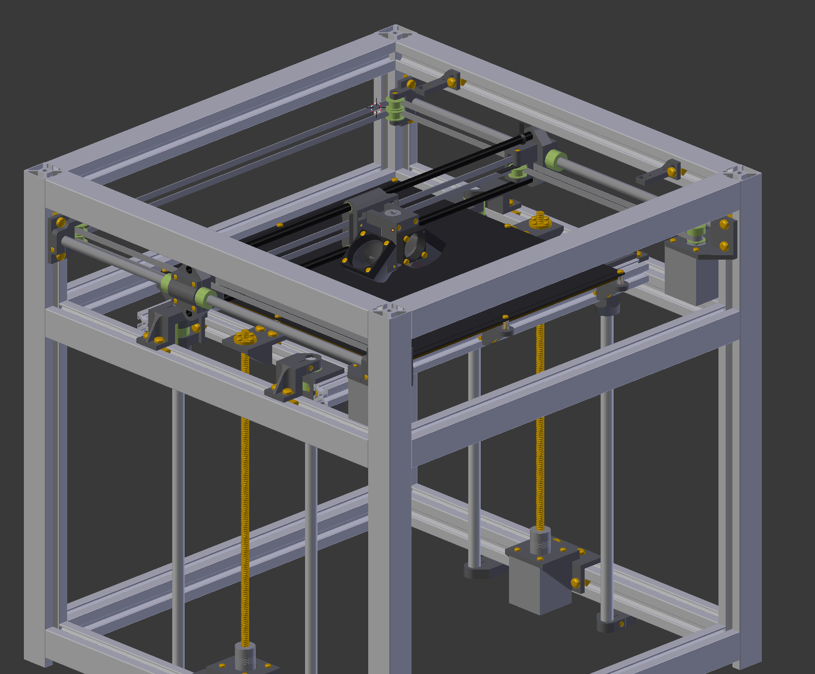
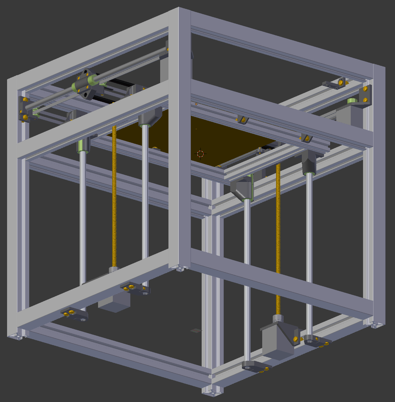
A few weeks ago I've started designing a new Core XY printer based on the Hypercube Evolution from Scott3D. My main goal was a 300x300x300mm build volume in a 500x500x500mm profile (+ bowden tube arc on top). Additionally, I want the XY-carriage to be as light as possible to reduce inertia as well as vibrations.
The current print volume stands just shy of my goal. The very front left and right cannot be reached due to interference between the fan ducts and the motor mounts. This results in ~20x10x300mm of lost space, which I consider tolerable, given that it is a mere .2% of the overall volume and very few models I know of require these areas to be unobstructed.
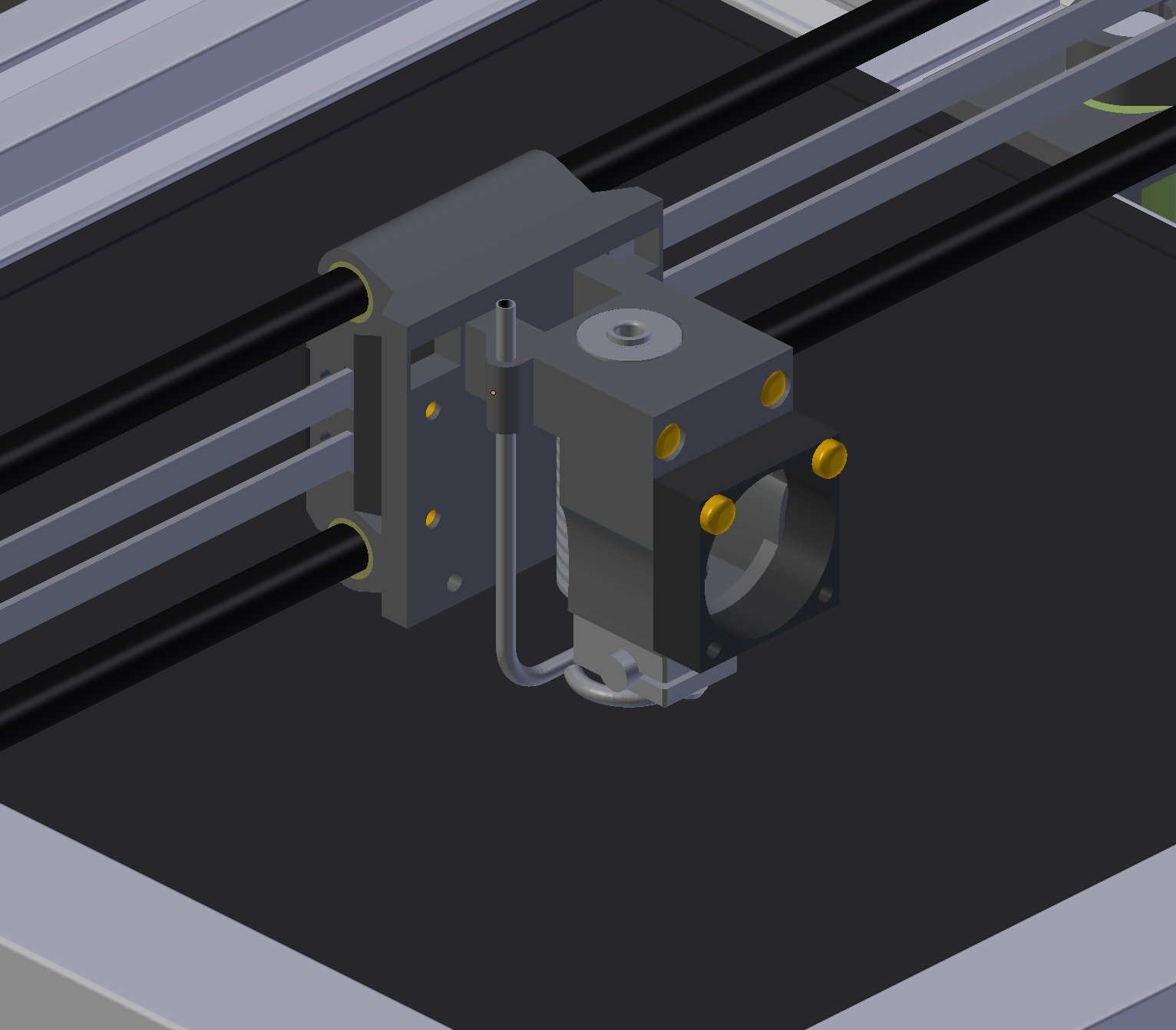
Four 12mm linear rails are used in conjunction with two lead screws to provide a stable build platform. Two 10mm rails are used for the Y and 2 8mm carbon tubes for the X axis. The latter significantly reduce the weight of the gantry and thus the moving mass of the printer.
Optical endstops are being used for both the X and the Y axis, while the Z axis does not yet have any endstops, but which I want to add later on.
All printed parts are intended to be very streamlined and simple to print. They all use nuts inserted during the print, as I consider this to be the most easy method.
Currently the thing that I am most unhappy with is the hotend assembly. I have seen great results using two 40mm cooling fans as you can see in the current pictures, but they do add quite a lot of weight and are responsible for the loss of volume. Using a top-down approach with a single fan might end up being sufficient event though it will move far less air.
I am also considering changing the Y-carriages by moving the bearings further to the front in relation to the X-tubes. This would move them closer to the gantries center of mass and give about 10mm more room to the back, thus eliminating the need for replacing the fans.
Please tell me what you think about the design thus far.
Blender file of the printer: [ufile.io]
Kind Regards
Cyclonit
A few weeks ago I've started designing a new Core XY printer based on the Hypercube Evolution from Scott3D. My main goal was a 300x300x300mm build volume in a 500x500x500mm profile (+ bowden tube arc on top). Additionally, I want the XY-carriage to be as light as possible to reduce inertia as well as vibrations.
The current print volume stands just shy of my goal. The very front left and right cannot be reached due to interference between the fan ducts and the motor mounts. This results in ~20x10x300mm of lost space, which I consider tolerable, given that it is a mere .2% of the overall volume and very few models I know of require these areas to be unobstructed.
Four 12mm linear rails are used in conjunction with two lead screws to provide a stable build platform. Two 10mm rails are used for the Y and 2 8mm carbon tubes for the X axis. The latter significantly reduce the weight of the gantry and thus the moving mass of the printer.
Optical endstops are being used for both the X and the Y axis, while the Z axis does not yet have any endstops, but which I want to add later on.
All printed parts are intended to be very streamlined and simple to print. They all use nuts inserted during the print, as I consider this to be the most easy method.
Currently the thing that I am most unhappy with is the hotend assembly. I have seen great results using two 40mm cooling fans as you can see in the current pictures, but they do add quite a lot of weight and are responsible for the loss of volume. Using a top-down approach with a single fan might end up being sufficient event though it will move far less air.
I am also considering changing the Y-carriages by moving the bearings further to the front in relation to the X-tubes. This would move them closer to the gantries center of mass and give about 10mm more room to the back, thus eliminating the need for replacing the fans.
Please tell me what you think about the design thus far.
Blender file of the printer: [ufile.io]
Kind Regards
Cyclonit
|
Re: Cyclonit's CoreXY December 06, 2017 05:52PM |
Registered: 10 years ago Posts: 24 |
|
Re: Cyclonit's CoreXY December 07, 2017 02:27AM |
Registered: 8 years ago Posts: 5,232 |
I see lots of brackets which are difficult to print by design. Did you print them yet or will you CNC them?
The idler bracket on the far right corner looks a bit undersized, if made from plastic. It should go around the corner, like the far left one.
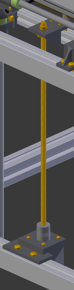
The lead screw nut holder would work better if mounted upside down. Then it supports the weight in "push" mode instead of "pull". The plastic would crack over time if constantly pulled... You'd also gain a few mm workspace, since the bed could be closer to the frame.
The idler bracket on the far right corner looks a bit undersized, if made from plastic. It should go around the corner, like the far left one.
The lead screw nut holder would work better if mounted upside down. Then it supports the weight in "push" mode instead of "pull". The plastic would crack over time if constantly pulled... You'd also gain a few mm workspace, since the bed could be closer to the frame.
|
Re: Cyclonit's CoreXY December 07, 2017 03:57PM |
Registered: 8 years ago Posts: 13 |
@gen2eng: Thanks for pointing me in that direction. I though about constructing something like that myself but I was unsure about its effectiveness. Giving that it appears to be an actually successful product, I'll take that route. It saves me a lot of space and actually grants more than the 300x300x300 volume now.
@o_lampe: Many of the parts will require support when printing, but I have quite some experience in printing objects like that and am willing to put in the extra effort. My current printer is capable of producing all of these parts and some testprints have been printed already.
You are right, the idlers at the back are a weakspot. Improving them shouldn't be to big of a problem, especially given that I now have some more room to play thanks to gen2eng's suggestion.
I've turned the nuts themselves upside down, thus they're now pushing against the nut holder from below. However, turning the entire holder upside down would actually reduce the Z-travel by several centimeters. Given that the holders are connected to the print beds extrusions from the side, I'd think they should last a long time.
Edited 1 time(s). Last edit at 12/07/2017 04:26PM by Cyclonit.
|
Re: Cyclonit's CoreXY December 07, 2017 07:23PM |
Registered: 11 years ago Posts: 1,049 |
Do yourself a favor
ditch the rods
use linear rails
see the digital dentist build
[forums.reprap.org]

ditch the rods
use linear rails
see the digital dentist build
[forums.reprap.org]
|
Re: Cyclonit's CoreXY December 08, 2017 05:29AM |
Registered: 6 years ago Posts: 1,007 |
Quote
cozmicray
Do yourself a favor
ditch the rods
use linear rails
see the digital dentist build
[forums.reprap.org]
I have to disagree, it should be "ditch everything" in place of "ditch the rods, use linear rails"
"A comical prototype doesn't mean a dumb idea is possible" (Thunderf00t)
|
Re: Cyclonit's CoreXY December 08, 2017 07:08AM |
Registered: 11 years ago Posts: 5,780 |
It's hard enough to get two end supported guide rails to be parallel to each other. Two rails provide all the needed constraint. Using four in Z is asking for the bed platform to walk or bind if there's any misalignment. I'm not saying you can't make it work, but what's the benefit of the extra cost and work?
How will the belts be tensioned in the XY stage?
Ultra MegaMax Dominator 3D printer: [drmrehorst.blogspot.com]
How will the belts be tensioned in the XY stage?
Ultra MegaMax Dominator 3D printer: [drmrehorst.blogspot.com]
|
Re: Cyclonit's CoreXY December 08, 2017 09:32AM |
Registered: 8 years ago Posts: 13 |
@cozmicray: I thought about using linear rails, but in all honesty I don't see the benefit justifying the extra effort. My current printer uses rods and it's precision is just fine.
@the_digital_dentist: Given that the bed is 300x300mm in size, I want to prevent the bed from twisting,thus the 4 rails. I have used the same layout in a test of mine and have never encountered any binding after everything was set up correctly.
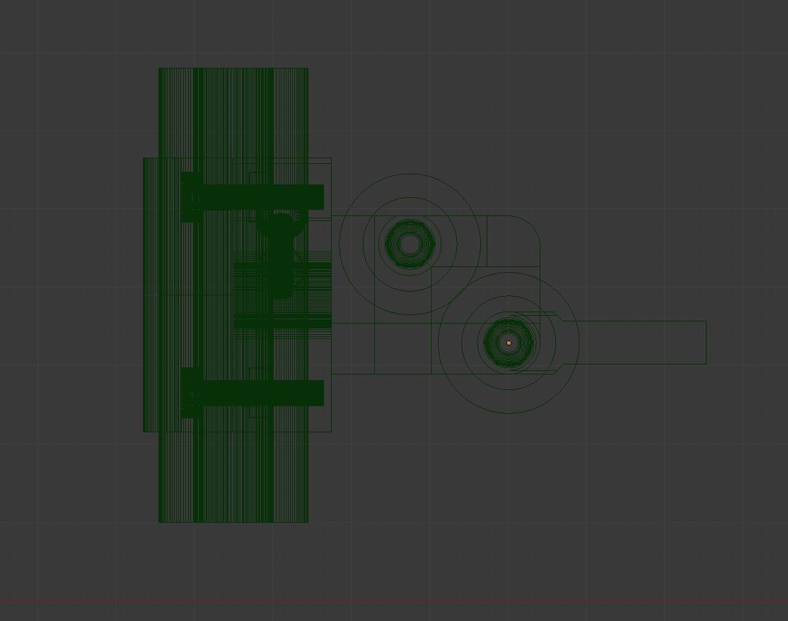
Tensioning is done though a mechanism at the back of the x-carriage. I'll provide a picture when I am home
@the_digital_dentist: Given that the bed is 300x300mm in size, I want to prevent the bed from twisting,thus the 4 rails. I have used the same layout in a test of mine and have never encountered any binding after everything was set up correctly.
Tensioning is done though a mechanism at the back of the x-carriage. I'll provide a picture when I am home
|
Re: Cyclonit's CoreXY December 08, 2017 12:08PM |
Registered: 8 years ago Posts: 13 |
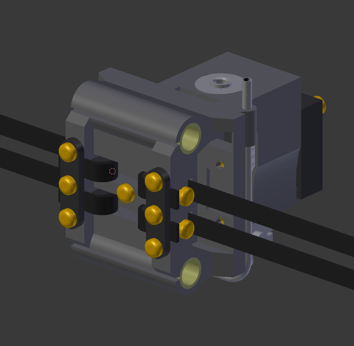
|
Re: Cyclonit's CoreXY December 08, 2017 02:12PM |
Registered: 11 years ago Posts: 5,780 |
That leads to another question- how are the pulleys at the ends of the X axis positioned? There is usually some offset between belts on each side of the extruder carriage because of using stacked pulleys at the ends of the X axis.
Ultra MegaMax Dominator 3D printer: [drmrehorst.blogspot.com]
Ultra MegaMax Dominator 3D printer: [drmrehorst.blogspot.com]
|
Re: Cyclonit's CoreXY December 08, 2017 04:11PM |
Registered: 8 years ago Posts: 13 |
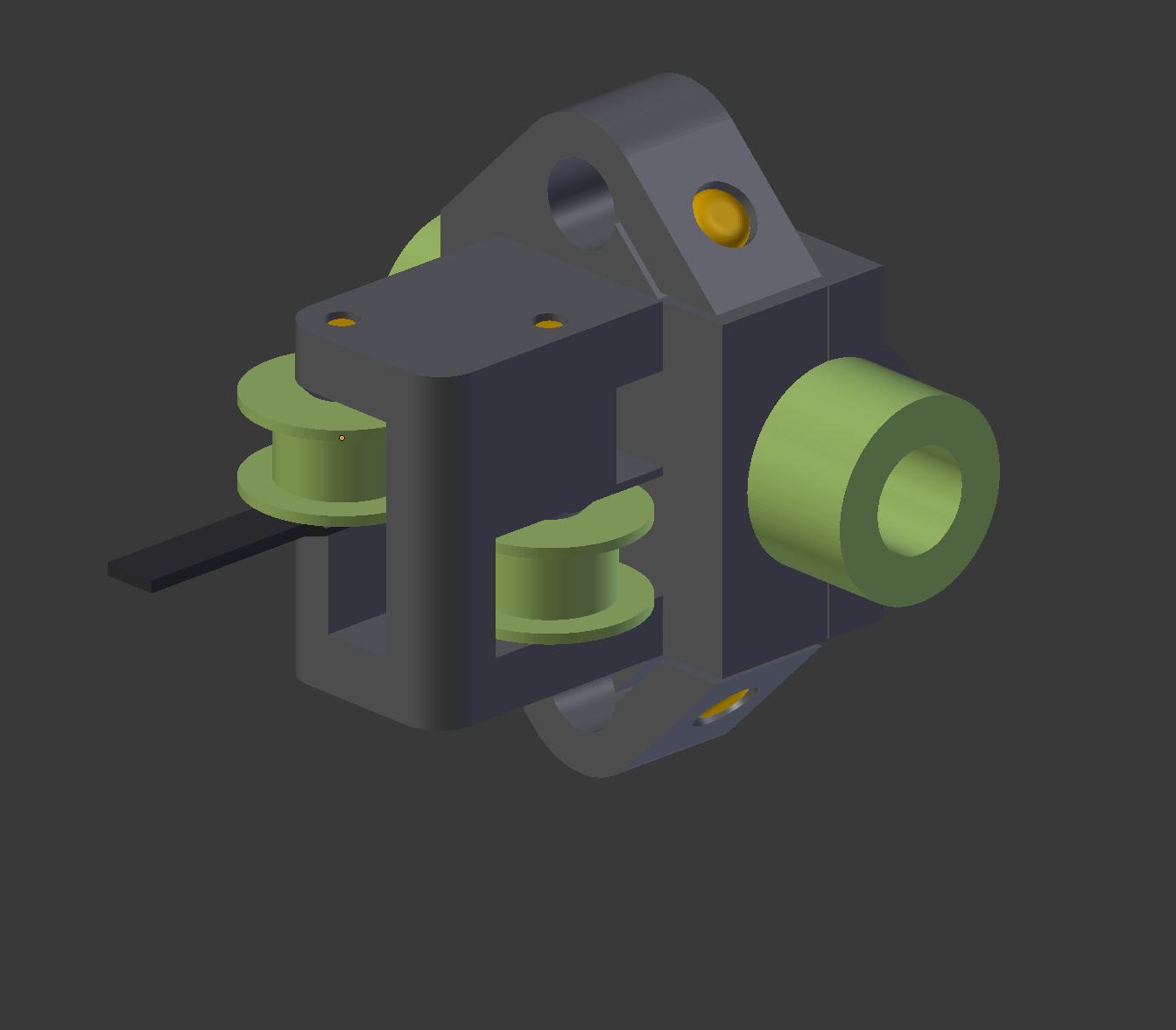
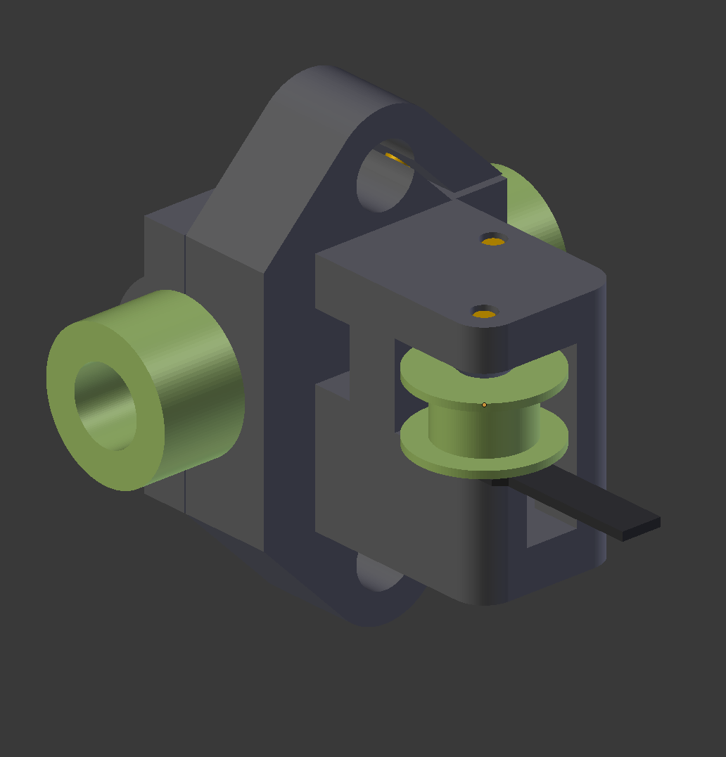
|
Re: Cyclonit's CoreXY December 13, 2017 06:43PM |
Registered: 6 years ago Posts: 20 |
I'm using four 12mm rails on the Z of my 400x400x400mm build area CoreXY, also based on the HyperCube Evo. Easy enough to align. I'm using a single motor and belt to drive both lead screws to eliminate any timing issues. Without the Stepper motor attached to resist the lead screws the Z assembly will fall under its own weight, no binding.
I have not checked the parallelism of the X rails but I do know the centering of the rod ends is slightly different from the bearing carrier for the nozzle which creates a little tension. So far it has not created any issues while printing.
I have not checked the parallelism of the X rails but I do know the centering of the rod ends is slightly different from the bearing carrier for the nozzle which creates a little tension. So far it has not created any issues while printing.
|
Re: Cyclonit's CoreXY December 30, 2017 01:32PM |
Registered: 8 years ago Posts: 338 |
Sorry, only registered users may post in this forum.