Witor's coreXY
Posted by witor
|
Witor's coreXY December 26, 2017 05:15PM |
Registered: 6 years ago Posts: 63 |
Firstly I would like to say hello as it is my first post on this forum.
I have spent past few weeks thinking about making a new 3d printer. I currently own an Anet A6 which is a decent printer (after a few mods). Initially, I wanted to make a Cartesian printer based on openbuild vrails and mini wheels that would be comparable to well-liked CR10 or Anycubic I3 mega. I started my design
and then I realised that I will just make another printer which will be just slightly better than my Anet and that I will put a lot of effort and money just to make a small improvement. It occurred to me that I want to go for something way better than my Anet, so I started researching various types of printers. I am somehow not convinced by delta setup and it looks like most of "serious" printers use coreXY mechanics. I have looked at many designs. Hypercube was the first, but I don't like linear bearings and rods. next one was Cbot and then Dbot. I liked the openbuild approach, but then I realised that 2 Z-axis motors will be difficult to keep in sync. I already had this problem with my Anet. I ended up linking 2 motors with gt2 loop belt.
I have discovered a video showing 3 leadscrews lifting the bed, but it is obvious that alignment will be a pain. 3 screws z axis
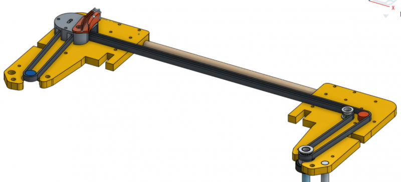
Using flexible couplers at the bottom supporting heavy bed is not the best as vibrations of the printer will make bed oscillate vertically as couplers will act as springs. I was considering using belts for z axis and then I have discovered Mark Rehorst's (Digital dentist's) blog Mark's blog
I will just put it this way - WOW! His approach is the best I have seen and I find it difficult to explain how impressed I am with his work. I seriously have no idea why there are so few corexy printers with belt driven z axis after what he has done. I my city have found a place similar to what Mark calls 'maker's place', and I hope that I will be able to do some metal work there.
After this lengthy intro this is what I want to achieve:
1) Build volume of 30x30x at least 30 cm
2) Top end quality prints.
3) Printing PLA, PETG, Nylon (don't think I will print ABS)
4) All metal frame as rigid as aluminium will allow all metal frame.
5) Speed - reasonable but not necessarily ultrafast.
6) Minimal adjustments, calibrations between prints - single motor wormgear and belt driven z axis.
6) Most difficult - all the above without breaking the bank.
Q1) I have to make a decision on how long linear rails for x and y axis have to be. Is 40cm enough to end up with 30cm usable print length, or do I have to have a final design to actually answer this question?
Q2) Thinking about points 2 and 6 from above I was looking at Robotdigg 440C Stainless Steel rails which have some reasonably good reviews. I have no idea what size I need. I thought about MGN15H for the z axis to minimise posibility of rotational wobble about x axis and MGN12 for Y axis. have no idea which would be suitable for X axis any syggestions? Do my estimated sizes make any sense? Could I go smaller and cheaper without sacrificing quality too much? (any comments on the rails choice would be appreciated)
Q3 Where should I start? Should I get the rails first and then work with what I got or design the whole thing and then hope that I will be able to find parts I need?
|
Re: Witor's coreXY December 26, 2017 10:44PM |
Registered: 11 years ago Posts: 5,780 |
Thanks for the compliments about my design. I am glad you're finding it useful. I am especially pleased with both the Z axis performance and the bed leveling system.
Regarding length of guide rails: I like to design from the inside of the printer out. Start at the extruder carriage- design it with all the junk you think you'll ever want to put on it. That will give you an idea of its size. Then, based on that size and your desired print XY dimensions, calculate the lengths of the guide rails required.
I shop ebay for used Japanese/German/Swiss/American guide rails. If I am going to build for 300x300 mm bed, the rails have to be at least 380-400 mm long. I start looking for guide rails that are at least that long and have the right number of bearing blocks. It's OK if they are longer than needed- you can cut them down using a cutoff wheel on an angle grinder.
I specifically avoid "MGN" guide rails. The originator of that designation is HiWin, a Taiwanese company that makes quality parts. But there are about 100 factories in China cranking out crappy knock-offs and using the same MGN part designator. Ebay is awash in them. Unless you buy directly from an official HiWin distributor or from HiWin, I wouldn't take the chance on anything with an MGN part number.
Designing the whole machine first, then trying to find parts that fit, will limit your choices and drive up costs. It is far easier and cheaper to design the machine around the parts as you acquire them. You can look for deals on parts when they become available, model them in CAD, and design as you go. It isn't the fastest process, but it does allow you to hold cost down while still building a very high quality printer.
Ultra MegaMax Dominator 3D printer: [drmrehorst.blogspot.com]
|
Re: Witor's coreXY December 27, 2017 05:54PM |
Registered: 6 years ago Posts: 63 |
I have already spent hours going through ebay, searching for linear rails with no success at all. I checked completed listing just to see if there was anything available in the past, still almost nothing. The fact that I am in the UK doesn't help we don't have as much stuff available as you do in the US.
I have only mentioned the MGN rails because I saw a few people saying that 440C made by the Robotdigg are decent. Not as good as genuine HiWin but better than all the other even cheaper crap on ebay. I am not in a hurry so I will take my time and hope that something better than Robotdigg MGN will show up, but if not I don't see much choice.
I have already started my design the way it was suggested above, from the hotend.
And I have a few questions
1) Does it really matter if x axis rail carriage is sliding in a horizontal plane, vertical plane or even upside down? Is there any advantage on putting it one way or the other?
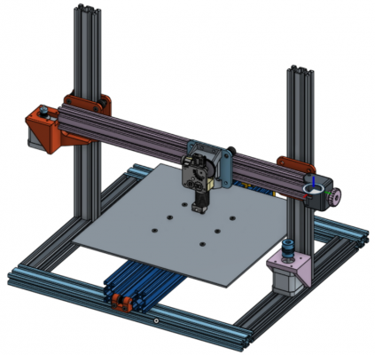
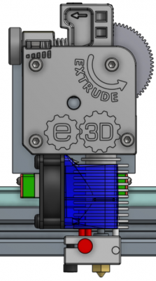
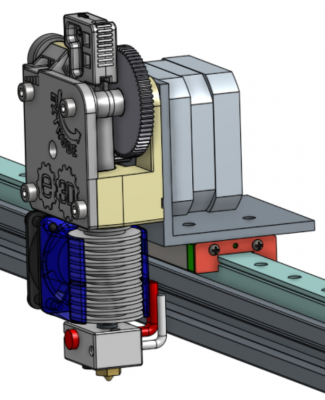
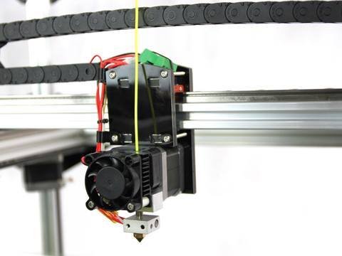
2) My first idea is shown on the pics. I presume there will be not enough heat from the hotend heatsink to affect the carriage and the rail next to it. Am I right?
3) X rail is mounted on 20x20mm aluminium extrusion (assuming that I will not get a better, wider rail) as I want to keep the whole x-axis assembly as light as possible. I hope that 20x20mm is enough to support E3d V6, titan extruder and thin pancake stepper. I will do some stress static and dynamic deformation analysis and will post the results.
4) On the UMMD distance between the bottom of the nozzle and the rail is rather large. Was there a specific reason for this?
|
Re: Witor's coreXY December 27, 2017 06:23PM |
Registered: 11 years ago Posts: 5,780 |
1) For most linear guides the position won't matter except maybe for the distribution and retention of lubrication. Use whatever way make mounting the extruder, pulleys, and belt clamps easiest.
2) I wouldn't worry about it. It's isn't much heat and the extruder is constantly in motion.
3) you'll just have to test it.
4) I have a CubeX printer that moves the bed in Z and has a large extruder carriage. It is damned near impossible to see what's happening as the first layer goes down with that printer. I don't like not being able to see the print, so I extended the extruder enough to allow me to see it easily. Also, I had a choice- to extend the bed mount and raise the bed higher or drop the extruder lower. I was more concerned about bed stability than the extruder, so I lowered the extruder. I may change that someday, but it's performing fine, so unless I am going to make other changes that require taking the machine apart, it's going to stay the way it is.
Ultra MegaMax Dominator 3D printer: [drmrehorst.blogspot.com]
|
Re: Witor's coreXY December 27, 2017 08:07PM |
Registered: 6 years ago Posts: 63 |
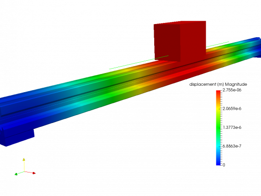
I have just done some analysis on the load. Image shows 400mm 20x20 aluminium V-slot with the 360g load under gravity in the middle. deformation seems to be negligible, so I believe that 20x20 extrusion should be enough.
|
Re: Witor's coreXY December 28, 2017 01:10PM |
Registered: 7 years ago Posts: 249 |
|
Re: Witor's coreXY December 28, 2017 09:42PM |
Registered: 6 years ago Posts: 63 |
Exactly. That's why I simulated extrusion only. If it is stiff enough (which it seems to be) with the rail it will be even stiffer.
The simulation made me think that the aluminium extrusion might actually be unnecessary as even relatively small (thin) rail should be stiff enough. I will run a few more simulations when I get the actual rails.
The simulation made me think that the aluminium extrusion might actually be unnecessary as even relatively small (thin) rail should be stiff enough. I will run a few more simulations when I get the actual rails.
|
Re: Witor's coreXY December 28, 2017 11:11PM |
Registered: 8 years ago Posts: 338 |
|
Re: Witor's coreXY December 29, 2017 08:35PM |
Registered: 7 years ago Posts: 249 |
Folgertech FT-5 uses linear rail on 2020, and they have a lot of experience.
Edited 1 time(s). Last edit at 12/29/2017 08:35PM by prot0typ1cal.
Edited 1 time(s). Last edit at 12/29/2017 08:35PM by prot0typ1cal.
|
Re: Witor's coreXY December 29, 2017 11:26PM |
Registered: 8 years ago Posts: 338 |
|
Re: Witor's coreXY December 30, 2017 12:47AM |
Registered: 7 years ago Posts: 249 |
Sorry, only registered users may post in this forum.
