My Dual Wire Gantry Printer
Posted by Celcius1
|
My Dual Wire Gantry Printer April 06, 2018 07:24AM |
Registered: 7 years ago Posts: 24 |
Hey Guys,
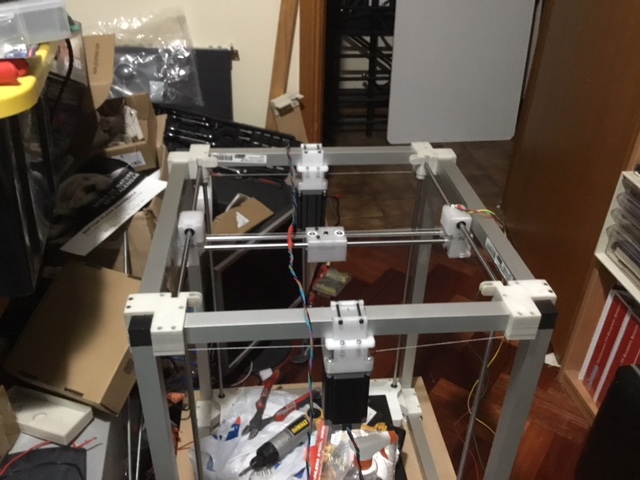
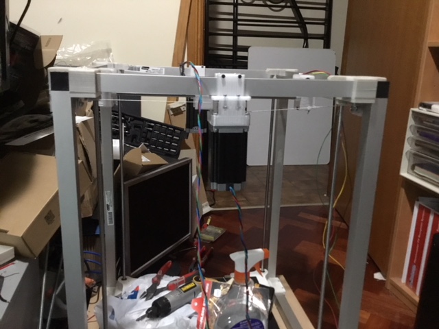
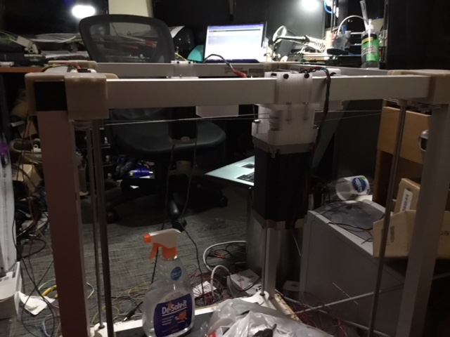
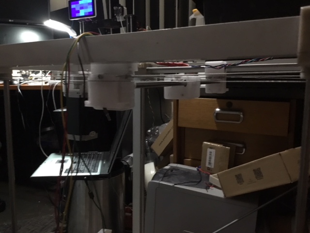
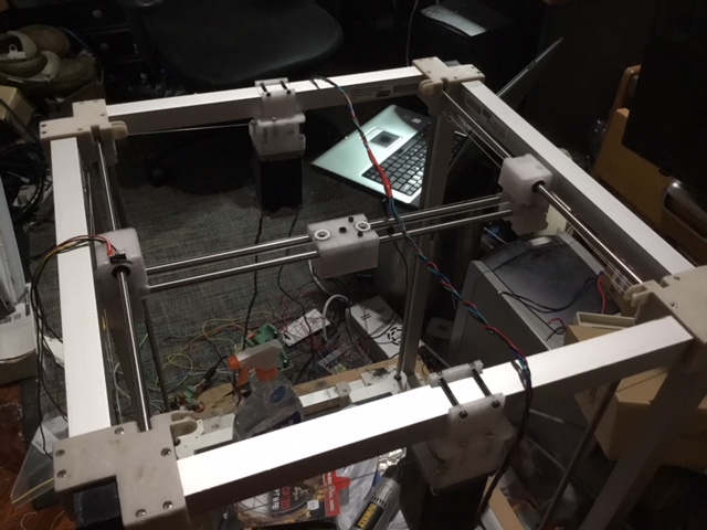
Here are some pics of my printer I am building (excuse the mess).
It has a build area of 350mm x 350mm x 410mm (Just measured the height of the print area), I use a Dual wire gantry for the X and Y movement, and its nice and sweet. and yes those are NEMA 23's yes I know its overkill but its what i had spare on the shelf!
I dont know the full height of the Z axis as I have yet to implement the Z lift, which I've ended up using good old leadscrews for. It's next on my list to get working I made the heated bed myself.
When the printer has a bit more complete I'll post some more pics.
Talk Soon
Celcius1
Edited 1 time(s). Last edit at 04/06/2018 07:36AM by Celcius1.
Here are some pics of my printer I am building (excuse the mess).
It has a build area of 350mm x 350mm x 410mm (Just measured the height of the print area), I use a Dual wire gantry for the X and Y movement, and its nice and sweet. and yes those are NEMA 23's yes I know its overkill but its what i had spare on the shelf!
I dont know the full height of the Z axis as I have yet to implement the Z lift, which I've ended up using good old leadscrews for. It's next on my list to get working
I made the heated bed myself.When the printer has a bit more complete I'll post some more pics.
Talk Soon
Celcius1
Edited 1 time(s). Last edit at 04/06/2018 07:36AM by Celcius1.
|
Re: My Dual Wire Gantry Printer April 30, 2018 08:32AM |
Registered: 7 years ago Posts: 24 |
|
Re: My Dual Wire Gantry Printer April 30, 2018 11:52AM |
Registered: 8 years ago Posts: 5,232 |
|
Re: My Dual Wire Gantry Printer June 25, 2018 11:47AM |
Registered: 6 years ago Posts: 4 |
Glad to see someone trying out string again!
The optimal number of wraps for a cable transmissions is:
F(hold) = F(pull)*e^-(Mu)*(theta)
Mu = friction coefficient between the cable and capstan (pulley)
Theta = wrap angle (one wrap = 2*pi in radian) # of wraps
If you know the required torque for your application, the motor gear ratio, the tension differential between the two terminated ends (Fhold/Fpull), and Mu, you can solve for theta which will give you how much to wrap the cable around the capstan.
Edited 1 time(s). Last edit at 06/25/2018 11:47AM by banana_muffin.
|
Re: My Dual Wire Gantry Printer August 27, 2018 04:54PM |
Registered: 7 years ago Posts: 24 |
Hey Guys,
Sorry I have not posted in a while real life unfortunately took over, but I have been working on my DW-G printer and have to say I'm going to CoreXY as the DW-G suffers from a similar racking issue as H-bot but it skews the axis (issue is with the Y-Axis) meaning calculation of the head skew is required no matter how stiff the frame, and this is as a result of the line coming in to tension, But this drawback can be alleviated using Linear Rails but I don’t have any. But in saying this what I have learnt with DW-G I can transfer over to the CoreXY design.
This is not a problem as when using line the method of implementation is different, it is a little more difficult but is much easier and cheaper to implement, with using belts the belt is not physically attached to the motor where as with DW-G is physically fixed and merely functions as a take up spool so no actual transition of line, so on both sides of the axis the line is a physical FIXED length so once tensioned the transmission of motion is directly applied, no line slip as there is no slip in the implementation. Which I found allowed for greater accuracy, the only downside is the line needs to be tensioned to a high tension for correct force transmission which also means designing the drive line to be straight otherwise the tension in the lines will cause a dragging effect in the axis that is with the DW-G design, another downside I'm hoping to alleviate by using the same implementation with a CoreXY, as in reality I found DW-G has its own draw backs but with what I learned with the DW-G design, I should be able to carry over to a CoreXY design and come up with a more better implemented CoreXY mechanism, removing the need for specialised belts. With the tensioning of the lines it has a total of 4 points of fixing, which means the use of four tensioning points this is a bit of annoyance but once tensioned there is no need to balance as it does not throw out the positional accuracy due to nature of how DW-G works, but it does create a skewing issue which I hope to alleviate with CoreXY, by going CoreXY with the same design methodology I should be able to get the tensioning points down to two on the head itself. Another issue is, that with DW-G the steps per axis are quite different, for the Y-Axis you could end up with for example 60 Steps whereas the X-Axis would be 120steps this makes life very hard in calibrating the printer.
Like I said above there is no need to calculate this, as I found with DW-G, the motor functions more along the lines of a fixed point with a take up spool, than a transfer of the line round the spindle as with belt configurations, and this is where I had to change my thinking when designing my DW-G as line functions very differently to belts and is implemented very much differently to a belt design, I will tell you this, this was my first approach to this design and went thru multiple iterations that kept failing. Until I went back to the drawing board and realised I was implementing the drive line wrong and forgot to take in the inherent design differences between belts and line, once I realised this I found how to get the design working.
As I am in the process of converting over to CoreXY i'll post an update with the change, and I'll also post a build process on how to use line effectively. With the Fishing line I used, I am in the process of setting up a web store so you can buy a length from me, but to give you an idea how cheap it is, I bought 50m of the fishing line for approx $15 Australian, so its super cheap and once you know how to implement it very useful as it has a 1 to 3% stretch component which is alleviated once pulled into tension.
Talk Soon
Celcius1
Sorry I have not posted in a while real life unfortunately took over, but I have been working on my DW-G printer and have to say I'm going to CoreXY as the DW-G suffers from a similar racking issue as H-bot but it skews the axis (issue is with the Y-Axis) meaning calculation of the head skew is required no matter how stiff the frame, and this is as a result of the line coming in to tension, But this drawback can be alleviated using Linear Rails but I don’t have any. But in saying this what I have learnt with DW-G I can transfer over to the CoreXY design.
Quote
o_lampe
It doesn't seem to matter, when the fishing line runs up/down along the stepper shaft?
Can you tell more about the specs of the line? How many turns around the shaft to keep it from slipping?
How did you tension both lines equally?
This is not a problem as when using line the method of implementation is different, it is a little more difficult but is much easier and cheaper to implement, with using belts the belt is not physically attached to the motor where as with DW-G is physically fixed and merely functions as a take up spool so no actual transition of line, so on both sides of the axis the line is a physical FIXED length so once tensioned the transmission of motion is directly applied, no line slip as there is no slip in the implementation. Which I found allowed for greater accuracy, the only downside is the line needs to be tensioned to a high tension for correct force transmission which also means designing the drive line to be straight otherwise the tension in the lines will cause a dragging effect in the axis that is with the DW-G design, another downside I'm hoping to alleviate by using the same implementation with a CoreXY, as in reality I found DW-G has its own draw backs but with what I learned with the DW-G design, I should be able to carry over to a CoreXY design and come up with a more better implemented CoreXY mechanism, removing the need for specialised belts. With the tensioning of the lines it has a total of 4 points of fixing, which means the use of four tensioning points this is a bit of annoyance but once tensioned there is no need to balance as it does not throw out the positional accuracy due to nature of how DW-G works, but it does create a skewing issue which I hope to alleviate with CoreXY, by going CoreXY with the same design methodology I should be able to get the tensioning points down to two on the head itself. Another issue is, that with DW-G the steps per axis are quite different, for the Y-Axis you could end up with for example 60 Steps whereas the X-Axis would be 120steps this makes life very hard in calibrating the printer.
Quote
banana_muffin
Glad to see someone trying out string again!
The optimal number of wraps for a cable transmissions is:
F(hold) = F(pull)*e^-(Mu)*(theta)
Mu = friction coefficient between the cable and capstan (pulley)
Theta = wrap angle (one wrap = 2*pi in radian) # of wraps
If you know the required torque for your application, the motor gear ratio, the tension differential between the two terminated ends (Fhold/Fpull), and Mu, you can solve for theta which will give you how much to wrap the cable around the capstan.
Like I said above there is no need to calculate this, as I found with DW-G, the motor functions more along the lines of a fixed point with a take up spool, than a transfer of the line round the spindle as with belt configurations, and this is where I had to change my thinking when designing my DW-G as line functions very differently to belts and is implemented very much differently to a belt design, I will tell you this, this was my first approach to this design and went thru multiple iterations that kept failing. Until I went back to the drawing board and realised I was implementing the drive line wrong and forgot to take in the inherent design differences between belts and line, once I realised this I found how to get the design working.
As I am in the process of converting over to CoreXY i'll post an update with the change, and I'll also post a build process on how to use line effectively. With the Fishing line I used, I am in the process of setting up a web store so you can buy a length from me, but to give you an idea how cheap it is, I bought 50m of the fishing line for approx $15 Australian, so its super cheap and once you know how to implement it very useful as it has a 1 to 3% stretch component which is alleviated once pulled into tension.
Talk Soon
Celcius1
|
Re: My Dual Wire Gantry Printer October 17, 2020 08:54AM |
Registered: 7 years ago Posts: 24 |
Thought I might revive this post,
I stopped posting on this printer as I ended up going to CoreXY, but the reason for reviving this post, is I am now going back to Dual Wire Gantry. But to build my printer as an IDEX.
And Judging from the pictures I posted back 2018 my printer has changed so much since I last posted these pics.
My printer is now a 2040/2060 extrusion frame, the aluminium tubing was a good idea but over time from use, and tension on the string/belts on the frame actually physically twisted! Sorry I did not take a photo when I transferred to a more sturdier frame.
I'm also using GT2 belts again, as they don't require nearly as much tension as string does to be accurate. And when string is tensioned like a coreXY could cause the X gantry to skew, and then skew compensation would need to be utilised.
I'm also going to be running an enclosed build chamber.
once the build area is enclosed, I'll be using two 100W 12V air heaters so positioned they create a convention current in the chamber, just need to figure out what thermistor is best to sense the chamber temp. Also my reason to go to DW-G again is it can also let me put the motors outside the chamber, keeping what is in the heated chamber to a minimum, I'll be limiting the chamber's temp to 90C as the sheeting being used to enclose it, is 6mm HDPE which is best to use for temps up to 130C but not any higher.
Its good I have a spare 12v 300w supply in my cupboard, been gathering dust for a few years.
Regards
Celcius1
|
Re: My Dual Wire Gantry Printer October 17, 2020 10:16AM |
Registered: 11 years ago Posts: 5,780 |
Cable drive is a PITA, especially for a precision positioning mechanism like a 3D printer.
I noticed in the pictures that the cables weren't parallel to the guide rails. That creates problems in cable drives as well as belt drives. The problem is that as the belt winds and unwinds from the drive pulleys, the points of entry and exit from the pulley move across it's surface. That changes the angle the cable makes with the guide rails which will cause the cable tension to vary with extruder position and can result in distorted prints. There are fancy multi pulley drives that can solve that problem, but it's all ends up being so much more trouble than belt drive that it's not worth the effort unless you just enjoy the challenge.
[vimeo.com]
Edited 1 time(s). Last edit at 10/17/2020 10:16AM by the_digital_dentist.
Ultra MegaMax Dominator 3D printer: [drmrehorst.blogspot.com]
I noticed in the pictures that the cables weren't parallel to the guide rails. That creates problems in cable drives as well as belt drives. The problem is that as the belt winds and unwinds from the drive pulleys, the points of entry and exit from the pulley move across it's surface. That changes the angle the cable makes with the guide rails which will cause the cable tension to vary with extruder position and can result in distorted prints. There are fancy multi pulley drives that can solve that problem, but it's all ends up being so much more trouble than belt drive that it's not worth the effort unless you just enjoy the challenge.

[vimeo.com]
Edited 1 time(s). Last edit at 10/17/2020 10:16AM by the_digital_dentist.
Ultra MegaMax Dominator 3D printer: [drmrehorst.blogspot.com]
|
Re: My Dual Wire Gantry Printer November 18, 2020 12:31PM |
Registered: 10 years ago Posts: 16 |
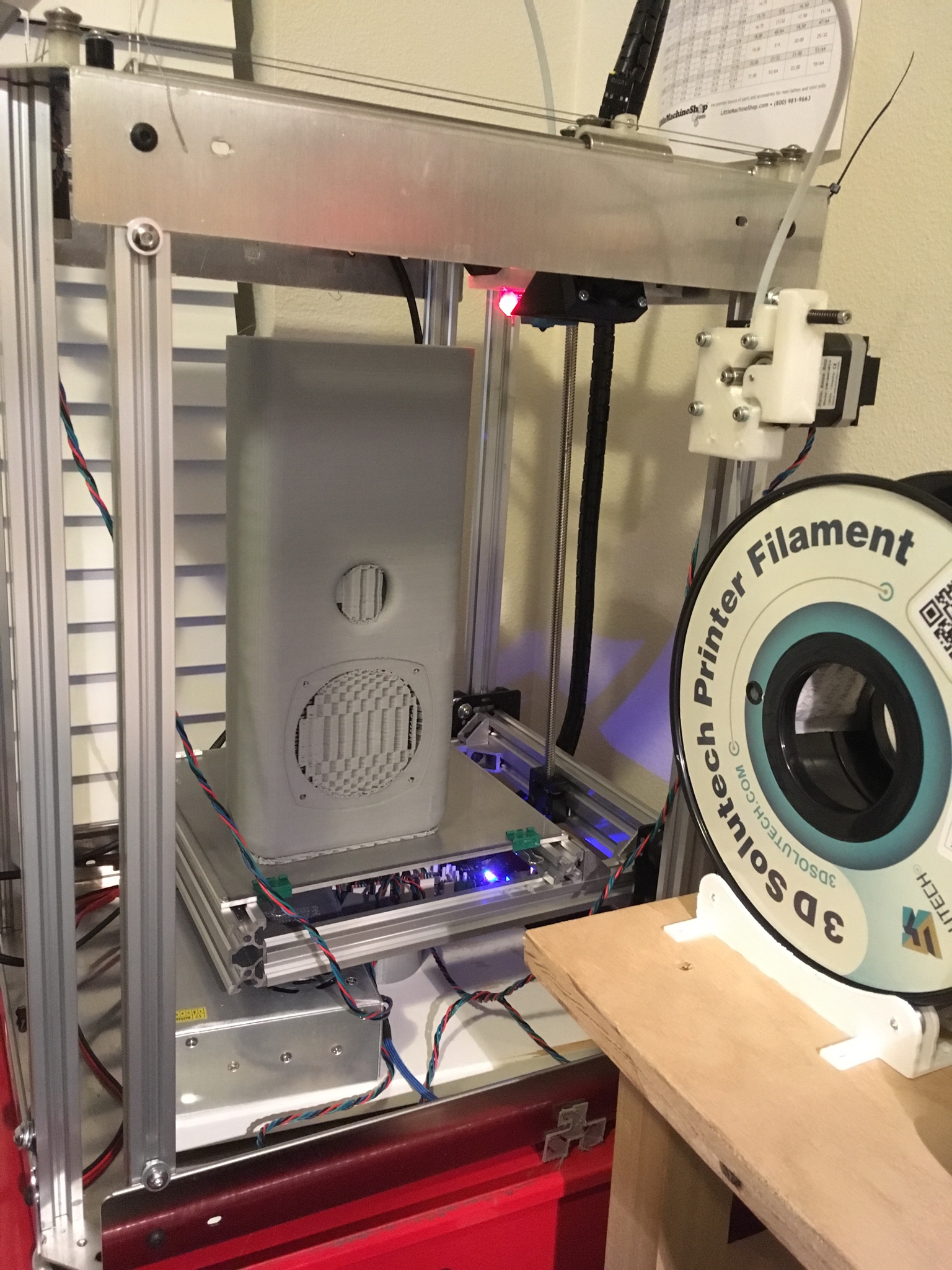
I just stumbled upon this thread. I have a functioning DWG printer that I designed, and has bee running for 4+ years now. Here is the Github repo with CAD (The main CAD is in Solidworks, but there is a subfolder with STEP files) https://github.com/pjoyce42/Pulley-Z-axis. If you're interested in more details, I can share pictures, and answer any questions you might have.
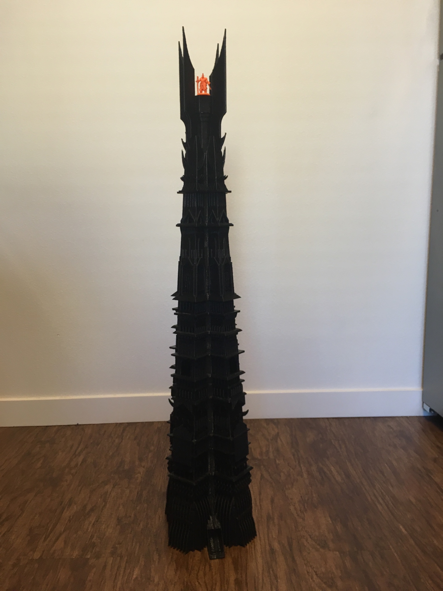
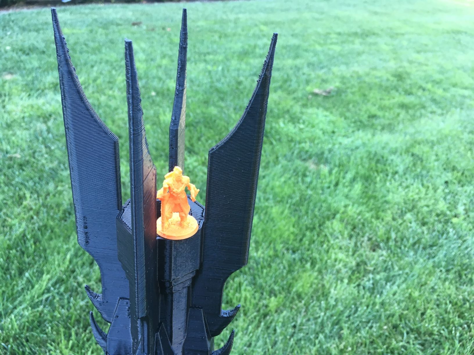
I've found DWG to be a very reliable kinematic system. The printer overall was very reliable until I put it inside an enclosure when it started jamming. (I think the solultion to that issue is to either bring it inside from the garage, and remove the enclosure, or switch to PETG). I've attached a few photos of things I printed over the years.
Also, this was a game changer as far as getting cable drive to work properly: Aluminum Wire Drive Spool. I have yet to find that item from another supplier, and it's absolutely necessary, IMO, to get a DWG working properly.
Edited 1 time(s). Last edit at 11/18/2020 12:34PM by pjoyce42.
Sorry, only registered users may post in this forum.