Presenting Piper 2 - CoreXY on EMT conduit frame Single Dual extruder moving gantry
Posted by piper3d
|
Presenting Piper 2 - CoreXY on EMT conduit frame Single Dual extruder moving gantry July 31, 2018 12:57PM |
Registered: 6 years ago Posts: 134 |
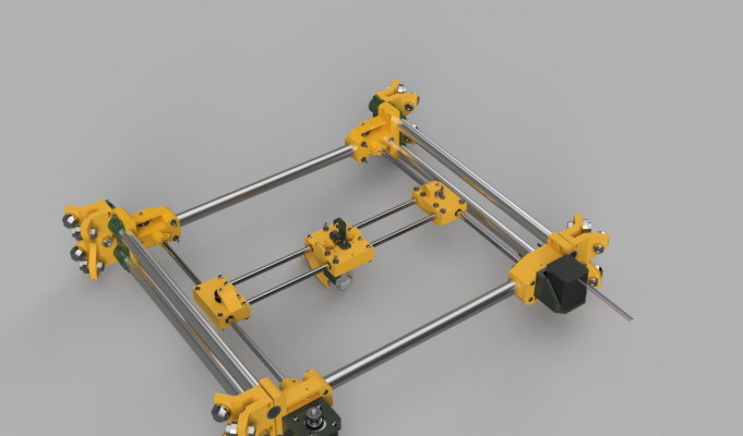
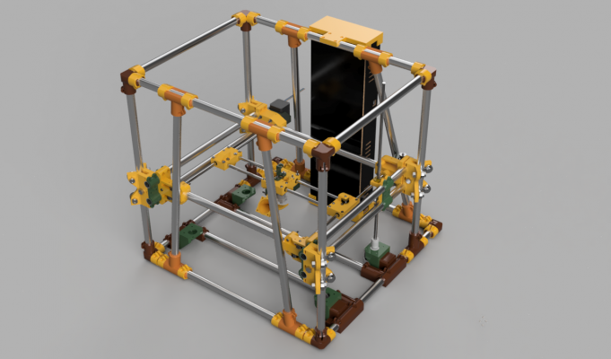
This is self-replicating (or partially self-replicating) machine.
CoreXY design with the upsidedown motor orientations - so no crossing belts.
Based on US EMT conduit frame and gantry (working on European or UK version at the moment).
It has a stationary bed so is relatively safe to use 120 or 220V heating pad.
It may have single or dual Bowden extruder.
Printable files are at [www.thingiverse.com]
Instructions are published at [piper3dprinters.com]
|
Re: Presenting Piper 2 - CoreXY on EMT conduit frame Single Dual extruder moving gantry August 01, 2018 12:48AM |
Registered: 8 years ago Posts: 5,232 |
Interesting design
From the looks I'd have made the corner brackets thicker. There are a few parts which look too thin and fragile and hard to print.
The diagonal struts would hinder me, when I try to peel off the part from the print bed.
And last but not least, I don't like the Z-axis' 4-motor mechanic.
From the looks I'd have made the corner brackets thicker. There are a few parts which look too thin and fragile and hard to print.
The diagonal struts would hinder me, when I try to peel off the part from the print bed.
And last but not least, I don't like the Z-axis' 4-motor mechanic.
|
Re: Presenting Piper 2 - CoreXY on EMT conduit frame Single Dual extruder moving gantry August 01, 2018 01:38AM |
Registered: 9 years ago Posts: 31 |
Quote
o_lampe
And last but not least, I don't like the Z-axis' 4-motor mechanic.
If the four motors are controlled independently, then the system actually has the benefit of being able to de-rack the gantry automatically based on z-probing. I believe the Voron v2 does this.
I'm not entirely convinced (yet) on conduit framing, but kudos on the design and execution. How far apart are the corexy belt planes? I would be concerned about racking forces on the y carriage.
|
Re: Presenting Piper 2 - CoreXY on EMT conduit frame Single Dual extruder moving gantry August 01, 2018 11:01AM |
Registered: 6 years ago Posts: 134 |
o_lampe Thank you for your critical observations.

"Diagonal struts" are as destructive as door frame in the boxed design.
Corner brackets were thicker until I came up with "joint brackets" design in Piper 1 which has moved to Piper 2. All parts are printed without support, there is a need to file off some overhangs in "arches" or cylindrical holes. The very first build I had is printing and traveling for the last 5 months. One of the last trips was in the front seat of Altima, imagine 600mm cube fitting into the front seatQuote
o_lampe
From the looks I'd have made the corner brackets thicker. There are a few parts which look too thin and fragile and hard to print.

Agree 95%, but it is a necessity with moving gantry. Gantry is heavier than the bed so it needs at least 3 points to be stable. One of my Piper 2s has 3 motors but it creeps on the side with a single motor. Currently, I am looking to solve it by working on an open belt driven Z with the single or dual motor. I do not like closed loop belts as they add additional constraints to the design.Quote
o_lampe
And last but not least, I don't like the Z-axis' 4-motor mechanic.
"Diagonal struts" are as destructive as door frame in the boxed design.
|
Re: Presenting Piper 2 - CoreXY on EMT conduit frame Single Dual extruder moving gantry August 01, 2018 11:32AM |
Registered: 6 years ago Posts: 134 |
Thank you, Nathanael.Quote
NathanaelXYZ
I'm not entirely convinced (yet) on conduit framing, but kudos on the design and execution.
Conduit design is at least 10 times cheaper than extrusion design, to some extent easier to work with and I am not expecting that it will be precisely cut. Extrusion design on other hand do require precise cutting in the shop rother than at home.
Belts are about 36mm apart, but 18mm from the movement plane they are symmetrical.Quote
NathanaelXYZ
How far apart are the corexy belt planes? I would be concerned about racking forces on the y carriage.
What artifacts in the print should I be looking for to see racking force intrusion? If this is uneven layers than the only uneven layers I saw on this printer were coming from Z wobbling
 .
.
|
Re: Presenting Piper 2 - CoreXY on EMT conduit frame Single Dual extruder moving gantry August 01, 2018 09:49PM |
Registered: 8 years ago Posts: 338 |
It is as important to cut the pipe precisely as it is to cut extrusion precisely.... i’m not sure the OD of emt conduit is consistent enough to give you good quality prints. But, i like the idea.
Use IMC instead, more heavy, more better.
Edited 1 time(s). Last edit at 08/01/2018 09:50PM by Qdeathstar.
Use IMC instead, more heavy, more better.
Edited 1 time(s). Last edit at 08/01/2018 09:50PM by Qdeathstar.
|
Re: Presenting Piper 2 - CoreXY on EMT conduit frame Single Dual extruder moving gantry August 01, 2018 11:42PM |
Registered: 6 years ago Posts: 134 |
Thank youQuote
Qdeathstar
But, i like the idea. .
Unfortunately you may cut, without special equipment, something with the tolerance of 1-2mm. It is acceptable for this printer, but it would not be acceptable for extrusions fitting.Quote
Qdeathstar
It is as important to cut the pipe precisely as it is to cut extrusion precisely.... .
|
Re: Presenting Piper 2 - CoreXY on EMT conduit frame Single Dual extruder moving gantry August 02, 2018 12:53AM |
Registered: 8 years ago Posts: 5,232 |
You save a little money over machined extrusions, but it'll be a hell of a time to align the frame and it'll cost you more when you have to buy special measurment tools.
You only have to buy the tools once and making a series production would eventually even out the bill. But series production of printed parts, were some parts need filing is no fun. Add the extra working hours to the bill and machined extrusions suddenly look much more appealing.
-only my 2 cent-
Olaf
|
Re: Presenting Piper 2 - CoreXY on EMT conduit frame Single Dual extruder moving gantry August 02, 2018 01:42AM |
Registered: 6 years ago Posts: 134 |
90% agree, you will add shipping costs and find that you do not need extrusions or pipes and you are building boxes out of 6mm acrylicQuote
o_lampe
... and machined extrusions suddenly look much more appealing.
Olaf
 But the best way is to sell parts as printers.
Please remember that I do have 2 of those machines already one is 300mm cube another is 250x250x300mm and it is not a hell to align them, XY plane is kept aligned by the tension of belts so Z is somewhat a problem, but not a big deal.
Out of all my biggest headake is wiring what has nothing to do with pipes or extrusions it consumes 60-70% of the time I spent building those machines. If somebody will sell a module with all electronics and wires in place It would be a relief.
|
Re: Presenting Piper 2 - CoreXY on EMT conduit frame Single Dual extruder moving gantry August 02, 2018 02:14AM |
Registered: 6 years ago Posts: 134 |
Those things, except music box, were printed on Piper 2 [www.thingiverse.com]
That egg - fire track btw has rotating wheels.
The message I am trying to deliver is that you do not need a hell of precision building 3d printers, but precision which is just "enough". I have friends who already spent close to $1.7K building 1 printer out of the best parts they can find. Piper 1 cost me $180 and Piper 2 close to $240 out of Amazon, Lowes, and McMaster retail parts. This is comparable to the cost of extrusions and linear motion necessary to build similar size printers out of the reputable shop.
|
Re: Presenting Piper 2 - CoreXY on EMT conduit frame Single Dual extruder moving gantry August 02, 2018 07:45AM |
Registered: 8 years ago Posts: 338 |
|
Re: Presenting Piper 2 - CoreXY on EMT conduit frame Single Dual extruder moving gantry August 02, 2018 09:43AM |
Registered: 6 years ago Posts: 134 |
|
Re: Presenting Piper 2 - CoreXY on EMT conduit frame Single Dual extruder moving gantry August 02, 2018 04:38PM |
Registered: 5 years ago Posts: 50 |
Quote
o_lampe
You save a little money over machined extrusions, but it'll be a hell of a time to align the frame and it'll cost you more when you have to buy special measurment tools.
You only have to buy the tools once and making a series production would eventually even out the bill. But series production of printed parts, were some parts need filing is no fun. Add the extra working hours to the bill and machined extrusions suddenly look much more appealing.
-only my 2 cent-
Olaf
Pardon my ignorance, but they actually sell machined extrusions? Regular extrusions, but machined to have flat surfaces?
|
Re: Presenting Piper 2 - CoreXY on EMT conduit frame Single Dual extruder moving gantry August 02, 2018 09:39PM |
Registered: 8 years ago Posts: 338 |
|
Re: Presenting Piper 2 - CoreXY on EMT conduit frame Single Dual extruder moving gantry August 02, 2018 09:42PM |
Registered: 8 years ago Posts: 338 |
|
Re: Presenting Piper 2 - CoreXY on EMT conduit frame Single Dual extruder moving gantry August 02, 2018 11:07PM |
Registered: 9 years ago Posts: 31 |
Quote
piper3d
What artifacts in the print should I be looking for to see racking force intrusion? If this is uneven layers than the only uneven layers I saw on this printer were coming from Z wobbling.
I was imprecise in my comment-- I am imagining twisting forces around the x-axis that would skew the parallel x-rods out of plane with each other. My hunch is that this would, if anything, lead to dimensional inaccuracies and perhaps slightly non-planar layers. However, it may well be that the ends of the y carriage (i.e. the pieces supporting the ends of the x-axis rods) are rigid enough that it is a non-issue.
|
Re: Presenting Piper 2 - CoreXY on EMT conduit frame Single Dual extruder moving gantry August 03, 2018 12:19AM |
Registered: 6 years ago Posts: 134 |
Quote
NathanaelXYZ
I was imprecise in my comment-- I am imagining twisting forces around the x-axis that would skew the parallel x-rods out of plane with each other.
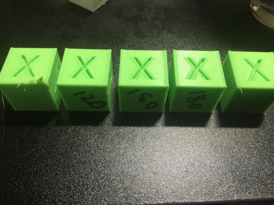
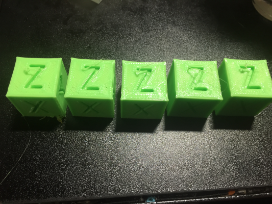
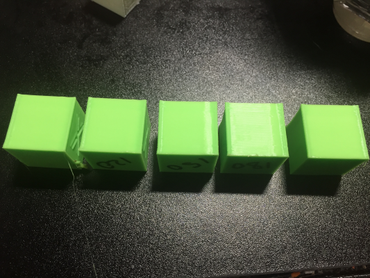
I started feeling that a little today. I had pushed Piper 2 to the limit and somewhere around 230 mm/s after 3 layers it started drugging the previous layer and messed up print, I think it may be a reason. (Jerk =7, acceleration 2000) Was testing Marlin 1.1.9 "S_CURVE_ACCELERATION" parameter. I am impressed by the new Marlin btw.
Test was done using Cura slicer (which is not using 100% speed all the time)
Bellow are results of my test from left to right 100, 120, 150, 180, 210 mm/s (speed set in Cura)
Edited 1 time(s). Last edit at 08/03/2018 12:20AM by piper3d.
|
Re: Presenting Piper 2 - CoreXY on EMT conduit frame Single Dual extruder moving gantry August 03, 2018 01:02AM |
Registered: 8 years ago Posts: 5,232 |
Quote
ruyvieira
Quote
o_lampe
You save a little money over machined extrusions, but it'll be a hell of a time to align the frame and it'll cost you more when you have to buy special measurment tools.
You only have to buy the tools once and making a series production would eventually even out the bill. But series production of printed parts, were some parts need filing is no fun. Add the extra working hours to the bill and machined extrusions suddenly look much more appealing.
-only my 2 cent-
Olaf
Pardon my ignorance, but they actually sell machined extrusions? Regular extrusions, but machined to have flat surfaces?
I get my extrusions cut to desired length and machined end-surfaces with no extra charge. Not sure, if that's what you meant?
I agree. It looks better than the render. And the locking parts now take care off the layerseperation issue.Quote
Oth, after watching the video, it looks beefy. And you could make it BIG very easily.
I don't fully agree with the statement' moved wires will eventually break' from the video. Sure you can make them brake by not following the rules. But for a slow moving Z-table, I don't see that risk. At 110VAC you can use long wires with wide bending radius' and silicone insulation. They might brake after 100.000 prints or so....
|
Re: Presenting Piper 2 - CoreXY on EMT conduit frame Single Dual extruder moving gantry August 04, 2018 03:35AM |
Registered: 7 years ago Posts: 507 |
100 prints is a pretty short lifespan for something like the wiring on the Z axis, especially since it only really moves up and down once per print. I3 style machines with a heatbed stress the cables several orders of magnitude more than a Z axis bed would and they print more than 100 prints usually.
I've been intrigued by lifting the gantry rather than the bed, but it always seems a bit sloppier. Having to evenly lift a square gantry seems to much harder than lifting/dropping a "point" and attaching a flat surface that you can level onto that. In theory its the same thing, lifting one planar object (XY gantry) vs another (bed), but I think a printbed is less prone to twisting if things dont lift evenly and has fewer forces on it during a print.
I've been intrigued by lifting the gantry rather than the bed, but it always seems a bit sloppier. Having to evenly lift a square gantry seems to much harder than lifting/dropping a "point" and attaching a flat surface that you can level onto that. In theory its the same thing, lifting one planar object (XY gantry) vs another (bed), but I think a printbed is less prone to twisting if things dont lift evenly and has fewer forces on it during a print.
|
Re: Presenting Piper 2 - CoreXY on EMT conduit frame Single Dual extruder moving gantry August 04, 2018 12:30PM |
Registered: 6 years ago Posts: 134 |
Quote
o_lampe
I don't fully agree with the statement' moved wires will eventually break' from the video.
And I am not trying to force
 . The exact quote from the video "eventually break", 100,000 moves are fitting into "eventually" range
  .
. Before adding high voltage heating bed the only risky point for high voltage are PSU and connection to the outlet. With the addition of the high voltage bed, the new line of dangers is exposed. Yes, you may protect yourself by using silicon wires or doubled insulation or somehow else. If you'll release your drawings to the public, the risk of somebody using low-quality wiring or not being careful and knowledgeable is increasing. From this point of view, I am considering stationary bed to be a safety feature embedded into the design.
|
Re: Presenting Piper 2 - CoreXY on EMT conduit frame Single Dual extruder moving gantry August 05, 2018 06:12PM |
Registered: 6 years ago Posts: 134 |
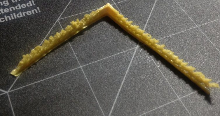
Yesterday have run a test on 300mm cube Piper 2 printing at 300mm/s. I printed walls of 200mm cube, 3 perimeters for a single layer have completed in 9 seconds (average speed 267 mm/s). Printers mechanics were able to run the head at the speed 300mm/s, but extruder has failed to melt the plastic with appropriate speed to keep up. Bellow is a fragment of the print. Corners look fine due to acceleration/deceleration 

|
Re: Presenting Piper 2 - CoreXY on EMT conduit frame Single Dual extruder moving gantry August 07, 2018 03:28PM |
Registered: 6 years ago Posts: 134 |
Have a video of 300 mm/s run https://youtu.be/D-Es5PkO1gk
|
Re: Presenting Piper 2 - CoreXY on EMT conduit frame Single Dual extruder moving gantry August 11, 2018 03:05PM |
Registered: 6 years ago Posts: 134 |
|
Re: Presenting Piper 2 - CoreXY on EMT conduit frame Single Dual extruder moving gantry August 11, 2018 03:18PM |
Registered: 6 years ago Posts: 1,007 |
Quote
piper3d
Nathanael, Thank you for the idea.Quote
NathanaelXYZ
If the four motors are controlled independently, then the system actually has the benefit of being able to de-rack the gantry automatically based on z-probing.
The advantage of having only one motor is that you don't need to "de-rack" and provided your machine is of a good design, rigid, properly constrained, accounts for thermal expansion, built with the proper components, you don't even need z-probing/auto bed leveling.
Edited 1 time(s). Last edit at 08/11/2018 03:20PM by MKSA.
"A comical prototype doesn't mean a dumb idea is possible" (Thunderf00t)
|
Re: Presenting Piper 2 - CoreXY on EMT conduit frame Single Dual extruder moving gantry August 11, 2018 04:20PM |
Registered: 6 years ago Posts: 134 |
Your statement is a good but unreachable goal. If you move your machine, no matter how good and rigid it is, you do. My friend is building industrial 3, 5, and 8 cubic meters printers from all the best components and huge extrusions with stress analysis and so on, imagine of moving that monster few inches, you will need to tune it again. Your best design will meet reality and 1 loose bolt may influence your bed positioning. How many recalls cars have? How many maintenance cycles they are going through? And cars are designed by the best engineers.Quote
MKSA
built with the proper components, you don't even need z-probing/auto bed leveling.
|
Re: Presenting Piper 2 - CoreXY on EMT conduit frame Single Dual extruder moving gantry August 12, 2018 02:12AM |
Registered: 8 years ago Posts: 5,232 |
|
Re: Presenting Piper 2 - CoreXY on EMT conduit frame Single Dual extruder moving gantry August 12, 2018 02:41AM |
Registered: 6 years ago Posts: 134 |
|
Re: Presenting Piper 2 - CoreXY on EMT conduit frame Single Dual extruder moving gantry August 12, 2018 05:10AM |
Registered: 6 years ago Posts: 1,007 |
Quote
piper3d
Your statement is a good but unreachable goal. If you move your machine, no matter how good and rigid it is, you do. My friend is building industrial 3, 5, and 8 cubic meters printers from all the best components and huge extrusions with stress analysis and so on, imagine of moving that monster few inches, you will need to tune it again. Your best design will meet reality and 1 loose bolt may influence your bed positioning. How many recalls cars have? How many maintenance cycles they are going through? And cars are designed by the best engineers.Quote
MKSA
built with the proper components, you don't even need z-probing/auto bed leveling.
If your machine requires frequent adjustments, it is normal due to the way it is built. Looking at just the Z axis; 4 lead screws, 4 guides and many bearings ... the assembly must be flexible as there is NO WAY to align all this perfectly thus a rigid set up would irremediably bind. Even, I wonder how many bearings are really bearing !
Anyway.
"A comical prototype doesn't mean a dumb idea is possible" (Thunderf00t)
|
Re: Presenting Piper 2 - CoreXY on EMT conduit frame Single Dual extruder moving gantry August 12, 2018 08:35AM |
Registered: 5 years ago Posts: 155 |
Quote
MKSA
The advantage of having only one motor is that you don't need to "de-rack" and provided your machine is of a good design, rigid, properly constrained, accounts for thermal expansion, built with the proper components, you don't even need z-probing/auto bed leveling.
I would take your rules of construction and add an automated measure + calibrate possibility. Then you have a low maintenance solution for consumers.
By measure I mean dial gauge (and spirit level) for perpendicular XY, flat Z and stored Z distance. By calibrate I mean small steppers who change two Z parameters and fix it (fixing by using worm drives e.g.).
Edited 1 time(s). Last edit at 08/12/2018 08:35AM by JoergS5.
|
Re: Presenting Piper 2 - CoreXY on EMT conduit frame Single Dual extruder moving gantry August 12, 2018 08:41AM |
Registered: 11 years ago Posts: 5,780 |
Eliminating adjustments is an achievable goal, just not the way you're building the printers. Both of the printers in my sig can be moved without adjustment, except maybe the leveling feet, if you happen to set either on an uneven surface. Neither has auto leveling, neither requires bed leveling adjustments after initial setup, unless I take them apart for modifications. I have moved both machines on several occasions, laying in my car, and when I get to the destination, I take them out, stand them up, and start printing without adjustments. Moving SoM is a two man operation. I can handle the much larger, but lighter weight, UMMD by myself.
The way I avoid having to make adjustments is through stable construction. I don't use any plastic parts in the structure of my printers- it's all metal bolted to metal, and the cross section of frame pieces is relatively large to minimize flex. I use linear guides bolted to flat plates or to frame members that have milled flat surfaces, so there's no worry about guide rails flexing. The bed support structure is designed to allow for thermal expansion of the plate without creating vertical displacements (UMMD, and soon SoM) that would affect leveling. In UMMD, the XY stage is designed to allow thermal expansion without the mechanism binding. Both printers can be enclosed and heated to print ABS without concern about plastic parts softening, expanding, or warping. Using a single motor in the Z axis in both printers also helps minimize the need for adjustments. It costs more to build this way. SoM has had about $1300 worth of parts go into and sometimes come out of it. I learned a lot about finding parts, etc., from SoM, so UMMD has been a more economical project at about $800 all-in.
TLDR: it isn't impossible to eliminate adjustments, but I don't think you can do it if you use printed plastic joints in the frame structure, motor mounts, linear bearings, etc.
Ultra MegaMax Dominator 3D printer: [drmrehorst.blogspot.com]
Sorry, only registered users may post in this forum.
