Presenting the NFAN CoreXY 3D printer
Posted by imqqmi
|
Presenting the NFAN CoreXY 3D printer September 11, 2018 06:34PM |
Registered: 9 years ago Posts: 752 |
I started out about 3 years ago with a Prusa i3 clone with a laser cut wooden frame. It was a great machine to learn about 3D printing. Just about everything was wrong with the machine so I started upgrading things and it improved a lot but I hit a certain level where it was just taking too much time and too little return of investment. The mechanics were so weak just looking at it would make it bounce and wobble. It was a lot of fun to tinker and hack with it though.
A year ago I built a diy cnc router, the Openbuilds OX. I used all Chinese parts and after a steep learning curve I was confident enough to mill out parts for a new 3D printer.
My goals were:
I've based my design on the CoreXY mechanics, inspired by the_digital_dentist, tech2c and many others and picked the things that spoke most to me. I had a lot of fun designing it in a 3D package.
here's a picture of the design:
http://www.makercentral.net/media/nfan/wip004v93.png
I machined the plates on the router. I used 3 and 6mm plates for stiffness. I accidentally ordered aluminium that was a bit too soft (1050 I think) to be machined but it plowed through after some adjustments liberal application of wd-40.
After most of the parts (pulleys, idlers, belts, v-slot wheels, etc) arrived I started building it and it came together without too much problems (to my surprise!). Some parts are on their way, and in the mean time used my old prusa i3 parts. The duet ethernet is yet to arrive so I used the arduino/ramps1.4 board for now with marlin 1.1.9. It has worked quite well so far, though the 12V stepper motor drives means the motors run relatively slowly at 80mm/s max. Hopefully the duet with 24V will double the speed.
The plan is to use an all metal hot end holder, but for now I used my old one which seems to work fine. I also used the old extruder for now.
Here's a short video showing the build print with test fitted steel reinforced belts. They're too stiff as the_digital_dentist said, I can confirm he's right
[youtu.be]
The very first print that came out was a lot better than what I've ever been able to print with the old Prusa i3 clone. The layers are very consistent, very little compliance/backlash and can print at 80mm/s without any ringing and resonances visible in the print. I used the same slic3r profiles I used with the prusa i3, so I didn't need to do any tuning.
Here's a macro shot of a 20x20x20mm hollow, single walled box:
http://www.makercentral.net/media/nfan/_MG_2230.jpg
Here's the corner view:
http://www.makercentral.net/media/nfan/_MG_2234.jpg
The layer height is 0.25 or 0.24, I can't remember. I realized at some point that the z steps are 0.04mm (lead screws with 8mm thread per turn, 200 steps per rev. 8/200 = 0.04, I use full step because the nema23 don't seem to run smoothly with 16x micro step) per step so 0.25 isn't possible to print exactly and may result in repeating z layer patterns.
Here's a space shuttle launch thing from thingiverse, reduced in size by a factor of 0.6. It stands about 30mm tall and 0.24 layer height, printed at 60mm/s (or as fast as the short layer times allowed, slowing down to 15mm/s at the top layers. I used an off print head 120mm 1000rpm cooling fan which may not have been enough cooling for those top layers.
http://www.makercentral.net/media/nfan/_MG_2254.jpg
http://www.makercentral.net/media/nfan/_MG_2223.jpg
 There are a few things that didn't work based on my design:
 What worked very well in my design:
All in all I'm really pleased how it turned out.
There are still some improvements I want to make:
If anyone is interested in the design files I'd be happy to share them, at least once I've ironed out the quirks.
Please let me know what you think! Any suggestions are welcome!
--
Kind regards
Imqqmi
NFAN CoreXY printer:
[reprap.org]
A year ago I built a diy cnc router, the Openbuilds OX. I used all Chinese parts and after a steep learning curve I was confident enough to mill out parts for a new 3D printer.
My goals were:
- Create an all metal 3D printer using my cnc router
- Make it really sturdy and stiff
- Easy to maintain and upgrade
- After setting it up it shouldn't need much more adjusting, I based the name on this goal: NFAN, No Further Adjustments Necessary. It's not how it is yet but it's a goal I'm striving for.
- Use the nema23 stepper motors I got with the CNC kit, for which I got three stepper motors with more torque so I had a few spare.
I've based my design on the CoreXY mechanics, inspired by the_digital_dentist, tech2c and many others and picked the things that spoke most to me. I had a lot of fun designing it in a 3D package.
here's a picture of the design:
http://www.makercentral.net/media/nfan/wip004v93.png
I machined the plates on the router. I used 3 and 6mm plates for stiffness. I accidentally ordered aluminium that was a bit too soft (1050 I think) to be machined but it plowed through after some adjustments liberal application of wd-40.
After most of the parts (pulleys, idlers, belts, v-slot wheels, etc) arrived I started building it and it came together without too much problems (to my surprise!). Some parts are on their way, and in the mean time used my old prusa i3 parts. The duet ethernet is yet to arrive so I used the arduino/ramps1.4 board for now with marlin 1.1.9. It has worked quite well so far, though the 12V stepper motor drives means the motors run relatively slowly at 80mm/s max. Hopefully the duet with 24V will double the speed.
The plan is to use an all metal hot end holder, but for now I used my old one which seems to work fine. I also used the old extruder for now.
Here's a short video showing the build print with test fitted steel reinforced belts. They're too stiff as the_digital_dentist said, I can confirm he's right

[youtu.be]
The very first print that came out was a lot better than what I've ever been able to print with the old Prusa i3 clone. The layers are very consistent, very little compliance/backlash and can print at 80mm/s without any ringing and resonances visible in the print. I used the same slic3r profiles I used with the prusa i3, so I didn't need to do any tuning.
Here's a macro shot of a 20x20x20mm hollow, single walled box:
http://www.makercentral.net/media/nfan/_MG_2230.jpg
Here's the corner view:
http://www.makercentral.net/media/nfan/_MG_2234.jpg
The layer height is 0.25 or 0.24, I can't remember. I realized at some point that the z steps are 0.04mm (lead screws with 8mm thread per turn, 200 steps per rev. 8/200 = 0.04, I use full step because the nema23 don't seem to run smoothly with 16x micro step) per step so 0.25 isn't possible to print exactly and may result in repeating z layer patterns.
Here's a space shuttle launch thing from thingiverse, reduced in size by a factor of 0.6. It stands about 30mm tall and 0.24 layer height, printed at 60mm/s (or as fast as the short layer times allowed, slowing down to 15mm/s at the top layers. I used an off print head 120mm 1000rpm cooling fan which may not have been enough cooling for those top layers.
http://www.makercentral.net/media/nfan/_MG_2254.jpg
http://www.makercentral.net/media/nfan/_MG_2223.jpg
 There are a few things that didn't work based on my design:
- The z axis lead screws were designed to be fixed with a bearing on both ends but it was over constrained and couldn't adjust it so it would be moving freely. I ended up removing the top one. The v-slot wheels are great at constraining any lateral movement so it has no impact on print quality. It's very smooth now. It actually drops on its own weight if the stepper motor isn't connected.
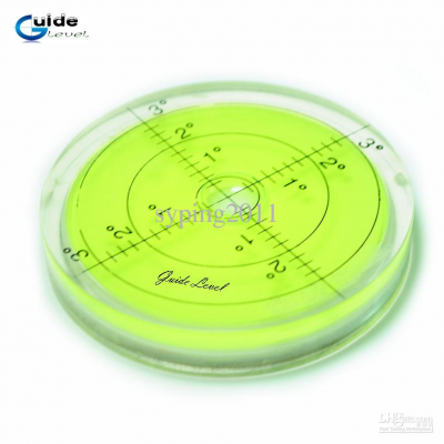
- The z plates needed slots instead of holes. Something went wrong during the machining stage of one of the z plates and it was off by 2-3mm. It's also a good thing to have slots to have better adjustment options to align the print bed extrusions with the xy gantry. I used a bubble level to get into the ball park, then used 2040 extrusions and let the top of the frame rest on the bed, then tighten the screws. It worked pretty well.
- I've leveled the aluminium heated bed with shims. I used four raiser plates of 5mm high to screw in the v-slot extrusion, and on the other end threaded holes for the heated bed to be mounted. This worked well except because of thermal expansion the bed would raise or drop by about 0.5mm making it hard to get the z offset adjusted correctly. I scraped the varnish off the glass plate numerous times until I loosen 3 screws on the raiser plates for the thermal expansion. The v-slots allow some room for expansion yet constrain the heated bed in the z direction. Simple yet effective so far.
- The aluminium heated bed (mk3) wasn't perfectly level. I made a mounting plate with an adapter for a dial indicator. With this I could measure the levelness (or lack thereof) of the heated bed. On one edge the offset was about 0.3mm. I used a glue clamp and another 2040 extrusion to bend it a bit more level. Overall the bed is now within 0.15mm level. It's hardly ideal but it'll have to do for now. If you have any tips where I can source an aluminium tooling plate and fitting silicone heating I'd greatly appreciate it! I like the setup of digital_dentist a lot, I think that's the way to go. I might have a look into the kinetic mounting method.
- The lion clamps are constantly in the way. This is in part due to the x carriage being a bit close to the print surface. It easily knocks them off. I may redesign the mounting so that the hot end sticks out more so it clears the clamps. I designed it like that as anything sticking out too much and moves around quickly will work like a spring so the closer the hot end is to the x carriage plate it will be stiffer.
- The nema23 stepper motors are high torque. This means if a step is done it will jump more than a nema17 stepper motor at low speeds. which leads to visible though very small ridges you can feel more than you can see. Hopefully the Trinamic 256x interpolation will smooth things out. I like the extra power though, high accelerations are possible. It's a bit noisy though.
 What worked very well in my design:
- The v-slot wheels with the eccentric nuts, this is really easy to design and build. It allows for some alignment errors to be adjusted away.
- the v-slot extrusions allows for endless upgrades and it's easy to enlarge the build volume. With v-slot nuts you can insert even if the ends are inaccessible is very convenient. You have the 'twist' time inserts but also wider, more robust ones with a little spring ball at the back. These stay put where ever you put them and have a longer thread, and won't damage the slot if you want to tighten it down.
- machining my own plates has worked so much better than I expected. Machining 1050 aluminium isn't easy but with shallow depth of cuts and lots of wd-40 it's amazing how such a non rigid cnc router can still deliver usable machined parts.
- the openbuilds delrin lead screw nuts are great! They are self lubricating and there are versions with anti backlash adjustment, though no backlash is to be found yet. Maybe if the nuts get worn more I may need to put the grub screws in and tighten it down. The advantage of these nuts is you don't need any lubrication, which only attract dust and may grind to a hold at some point.
- All the idlers are supported at both ends with 6mm thick plate aluminium instead of springy printed plastic parts. I think this has really helped make stuff stiff, despite the aluminium rods for the idlers.
- The z axis end stop. I just use a regular micro switch without any adjustment. I put it somewhere along the z extrusion so it's in the ballpark. When homing, x and y must be homed first. The frame is large enough that the nozzle isn't over the heated bed so the z axis can raise up higher. It hits the end stop, then I use an eeprom settable variable with M206 Z-5.3 or something to shift the z axis back in position. This way I don't need an end stop adjustment screw, I can just use software to adjust the z height. It's the same idea as using a servo lowered z probe I used on the old prusa i3. It used an offset too. Hopefully this will work the same with the duet.
All in all I'm really pleased how it turned out.
There are still some improvements I want to make:
- Replace the hotend holder with all metal machined aluminium, or reprint it with single hotend holder.
- Design and machine a new extruder/cold end drive
- Replace the 5mm aluminium smooth rods for the idlers. It doesn't seem to have much impact on print quality at 80mm/s though but some hardened steel smooth rods are ordered.
- Replace the 6mm glass reinforced belts with 10mm. All the pulleys and idlers are 10mm so it should be an easy fix. Even so, hardly any compliance or backlash is visible, even at 80mm/s but I may see it if I push beyond that speed.
- replace the ramps1.4 board with a duet ethernet so I can put it somewhere more convenient and with trinamic stepper motors with 256 interpolation mode should make it much quieter and smoother and hopefully faster at 24V.
- The design shows the back 2020 vertical supports but in my actual build printer it's located at the front. I will add 2040 support on the back as well later for extra stiffness. The frame may be slightly over build that way, still there's a bit of flex I want to get rid of.
- once all parts have arrived I'll clean up the wiring and put the electronics in a metal case.
- I need to sort out the psu. I want to use a single 24V psu with a 12V buk converter eventually. Still, I can hear the stepper motors whine, and when the heater cartridge in the hot end is at its set point, you can hear the motor whine pitch shift in the rhythm of the pid frequency. I'm not sure if this translates into the print. I'll have to think of a way to test this. Led PSU's aren't the best for changing inductive and resistive loads.
- I've ordered 10 pin connectors with screw terminals for the x carriage to be able to easily switch tool heads. I'm planning to add a dremel/light spindle for pcb milling and a laser module. I like the tool changer E3D has designed. I may give it a shot when they've released the design files and maybe sell parts for it.
- The disadvantage of the z end stop at the moment is that some space is wasted, so a larger heated bed covering the entire area of the build volume isn't possible. I use a 200x200mm mk3 heated bed for now. I'll have to come up with a different solution if I use a 300x300mm bed. I may look into the piezo devices. I've got a diy prototype based on DjDemonD precision piezo z-probe ideas. If you look closely, the design has a pad with a circle in it, which is the piezo disk. The idea is to have a fixed location on the z axis extrusion. Use the nozzle or gantry to hit the plate and trigger the z end stop.
- To be able to properly print ABS, the printer needs an enclosure. I'm playing with the idea of using acrylic plates with neodynium magnets to keep them in place. I'm not sure if it'll rattle badly or if it's alright. It's easy to remove panels with magnets.
- add led strip lighting.
- print or buy some dragchains to make wiring a bit neater.
If anyone is interested in the design files I'd be happy to share them, at least once I've ironed out the quirks.
Please let me know what you think! Any suggestions are welcome!
--
Kind regards
Imqqmi
NFAN CoreXY printer:
[reprap.org]
|
Re: Presenting the NFAN CoreXY 3D printer September 17, 2018 04:20PM |
Registered: 5 years ago Posts: 71 |
Nice design! Looks like many hours of milling there. My DIY printer is somewhat similar with the two 20x80mm upright supports. I found i needed diagonal cross-braces on the exterior of the frame when printing at higher speed to keep frame flex at bay. Your test print looks good, so maybe you're alright there.
For the bed plate, google 'aluminum tooling plate mic-6', any number of online vendors like OnlineMetals.com carry it.
For the silicone heater, I used the SRFG-1212/5 (12in x12in, 5W/in2) directly from Omega.com (https://www.omega.com/pptst/SRFR_SRFG.html). You'll need a SS relay to control it. They have heaters with PVA glue too if needed. Mine is sandwiched between cork and the bed plate.
Edited 1 time(s). Last edit at 09/17/2018 08:31PM by gmedlicott.
Quote
imqqmi
Overall the bed is now within 0.15mm level. It's hardly ideal but it'll have to do for now. If you have any tips where I can source an aluminium tooling plate and fitting silicone heating I'd greatly appreciate it! I like the setup of digital_dentist a lot, I think that's the way to go. I might have a look into the kinetic mounting method.
For the bed plate, google 'aluminum tooling plate mic-6', any number of online vendors like OnlineMetals.com carry it.
For the silicone heater, I used the SRFG-1212/5 (12in x12in, 5W/in2) directly from Omega.com (https://www.omega.com/pptst/SRFR_SRFG.html). You'll need a SS relay to control it. They have heaters with PVA glue too if needed. Mine is sandwiched between cork and the bed plate.
Edited 1 time(s). Last edit at 09/17/2018 08:31PM by gmedlicott.
|
Re: Presenting the NFAN CoreXY 3D printer September 18, 2018 03:04AM |
Registered: 9 years ago Posts: 752 |
Thanks gmedlicott! I'd like to see your design, do you have a post or video about it?
The Nema23 steppers can't yet reach high velocities (at 80mm/s is about the maximum), I can't see it flexing as much as just shaking. I need to pin it down on a more solid surface I think. I'll experiment with crossbracing, it's easy to do with the v-slots. I've printed a 600mm drag chain for the xy motion part and came out ok. Thin walls printed at 60mm/s is a bit too fast I guess
Thanks for the recommendation for the bed, the mic-6 keyword really helped to zero in on actual webshops that sell them with a price tag. At some point I've found a supplier in the UK and Germany. I'm not yet sure about the tolerances but I'll send them an email and find out.
Here's a short clip printing an articulated toy downloaded from thingiverse. It came out nice, but the sharp corners did have some ringing. Hopefully installing the 10mm belt and putting more tension on them will help.
[youtu.be]
--
Kind regards
Imqqmi
NFAN CoreXY printer:
[reprap.org]
The Nema23 steppers can't yet reach high velocities (at 80mm/s is about the maximum), I can't see it flexing as much as just shaking. I need to pin it down on a more solid surface I think. I'll experiment with crossbracing, it's easy to do with the v-slots. I've printed a 600mm drag chain for the xy motion part and came out ok. Thin walls printed at 60mm/s is a bit too fast I guess

Thanks for the recommendation for the bed, the mic-6 keyword really helped to zero in on actual webshops that sell them with a price tag. At some point I've found a supplier in the UK and Germany. I'm not yet sure about the tolerances but I'll send them an email and find out.
Here's a short clip printing an articulated toy downloaded from thingiverse. It came out nice, but the sharp corners did have some ringing. Hopefully installing the 10mm belt and putting more tension on them will help.
[youtu.be]
--
Kind regards
Imqqmi
NFAN CoreXY printer:
[reprap.org]
|
Re: Presenting the NFAN CoreXY 3D printer September 18, 2018 07:47PM |
Registered: 5 years ago Posts: 71 |
|
Re: Presenting the NFAN CoreXY 3D printer September 20, 2018 06:04PM |
Registered: 9 years ago Posts: 752 |
I'm looking forward to it! The longest run is about 450mm. I've also noticed microdtepping isn't smooth it jumps going slower and faster through a full step. Especially at shallow angles the extrusion lines get very slightly wavy. I'm not going to put time in tuning the ramps stepsticks as I switch to a duet soon. I hope the duet trinamic steppers will do a better job. I've also received 16 tooth pulleys to replace the 32 tooth ones, that should double the steps per mm and give better resolution. The infill pattern is a bit irregular in a way most likely due to rounding errors and coarse resolution an steppers not running smoothly.
Still, prints come out much better than my old prusa i3 clone, which I've now dismantled. I'm sure the components will come in handy. More often the prints are dimensionally correct and fit better with joints and hinges like drag chains.
Here's a short video printing an articulated dolphine printed with pla. I thought it would definitely mess up the hinges but it was fine, it hinges very smoothly.
[youtu.be]
--
Kind regards
Imqqmi
NFAN CoreXY printer:
[reprap.org]
|
Re: Presenting the NFAN CoreXY 3D printer September 23, 2018 08:41AM |
Registered: 9 years ago Posts: 752 |
The duet controller hasn't arrived yet, so I've decided to adjust the motor current to see what difference it would make.
The procedure I used:
I printed out a slab of 20x20x2mm.
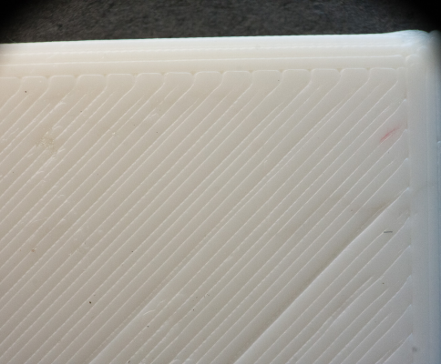
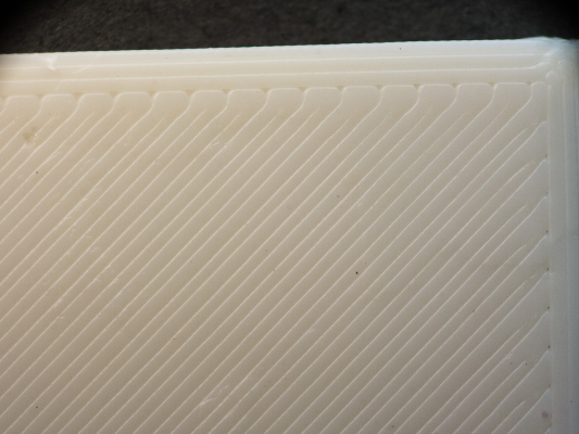
The bottom side before. You can clearly see the uneven spacing of the infill caused by the 'jumping' of the microsteps:
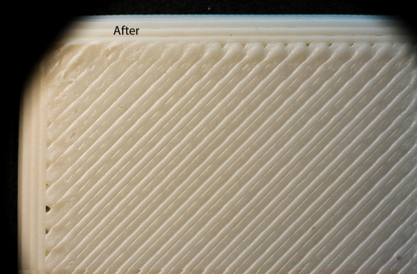
This is after adjusting, also the bottom of the print. You can see the infill is much more regular compared to the image above:
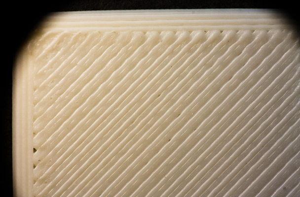
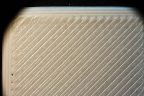
Here's the before again, but of the top infill. You can clearly see the lines aren't straight and 'blobs' more to the point gaps appear between the infill lines.
And finally the adjusted motor current, top of the part. The lines are straighter, less blobbing. It isn't perfect but a lot better.
Here's an animated gif of the top infill (click to enlarge and animate):
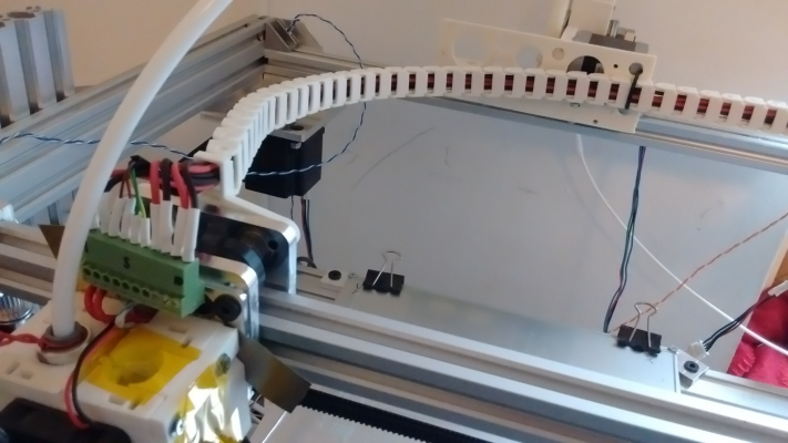
The drag chain has been installed, and while I was at it, I've also added 10 pin connectors to the x-carriage and the other end of the cable. Now I can easily change the hot end for a laser module without having to reroute cables through the chain. Just undo the three bolts and disconnect the connector. It's a long way from an automatic tool changer though. And because the other end also has a connector I can more easily swap controllers as well. The plates sticking out of the hot end holder are shims I've placed to reduce wobble of the hotend because the bowden tube is relatively stiff and rotates the hotend slightly. I'm going to redesign the hot end holder to be all metal or I'll make an improved 3D printed version (to keep it light). I'll pay extra attention to the back to be perfectly flat so it doesn't wobble.
Edited 2 time(s). Last edit at 09/23/2018 08:45AM by imqqmi.
--
Kind regards
Imqqmi
NFAN CoreXY printer:
[reprap.org]
The procedure I used:
- I used a digital volt meter (DVM) and put the negative to ground and attached positive to to the screwdriver
- I setup the printer so it moves really slowly using G1 X50 Y50 F10. This moves only one stepper in a corexy configuration.
- The jumps were clearly visible, speeding up and slowing down as the stepper cycles through the microsteps. It was also very audible.
- I adjusted the motor current up and the jumps got worse. I was at 0.59V and reached 0.9V. Then I adjusted it down to 0.39V which is just on the edge of jumping and not jumping.
- Now it runs pretty smoothly.
- After that I used G1 X0 Y100 F10 which only moves the other motor. Same process as above.
- And again G1 Z50 F10 which moves the z motor. Same process as above.
I printed out a slab of 20x20x2mm.
The bottom side before. You can clearly see the uneven spacing of the infill caused by the 'jumping' of the microsteps:
This is after adjusting, also the bottom of the print. You can see the infill is much more regular compared to the image above:
Here's the before again, but of the top infill. You can clearly see the lines aren't straight and 'blobs' more to the point gaps appear between the infill lines.
And finally the adjusted motor current, top of the part. The lines are straighter, less blobbing. It isn't perfect but a lot better.
Here's an animated gif of the top infill (click to enlarge and animate):
The drag chain has been installed, and while I was at it, I've also added 10 pin connectors to the x-carriage and the other end of the cable. Now I can easily change the hot end for a laser module without having to reroute cables through the chain. Just undo the three bolts and disconnect the connector. It's a long way from an automatic tool changer though. And because the other end also has a connector I can more easily swap controllers as well. The plates sticking out of the hot end holder are shims I've placed to reduce wobble of the hotend because the bowden tube is relatively stiff and rotates the hotend slightly. I'm going to redesign the hot end holder to be all metal or I'll make an improved 3D printed version (to keep it light). I'll pay extra attention to the back to be perfectly flat so it doesn't wobble.
Edited 2 time(s). Last edit at 09/23/2018 08:45AM by imqqmi.
--
Kind regards
Imqqmi
NFAN CoreXY printer:
[reprap.org]
|
Re: Presenting the NFAN CoreXY 3D printer September 24, 2018 05:22PM |
Registered: 9 years ago Posts: 752 |
Last weekend I've designed a led lamp holder for a gooseneck led lamp build I'm making. I've ordered a gooseneck of 600mm, longer than usual. It's going to be used as a work light, to point at things I'm working on. I like the spotlight kind to highlight certain details. I already have a ready made commercially availabe led lamp but the base of it is always in the way. I also want to make a version with a spring clamp. This too I also have ready made, but I'd like the clamp to be bigger so it fits on thicker table sheets and posts. Luckily I've found the exact same model that I own on Aliexpress.
For the led light I've bought a Phillips led bulb spotlight for 12V AC, but also works on 12V DC. It's smallish and not too bright for close up use about 175 lumen IIRC.
The design was made in SolidWorks, to keep my meager modeling skills in form.
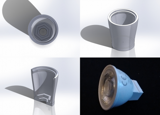
Here's the design. I used a pocket for the nut to fit into. The gooseneck ends are already threaded:
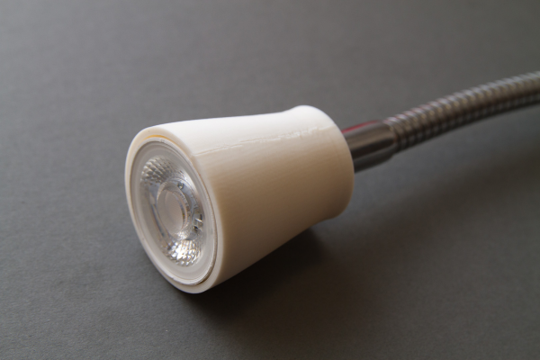
It printed pretty well, at 65mm/s for outer perimeters and infill at 83mm/s. It's about 40mm high printed at 0.24 layer height.
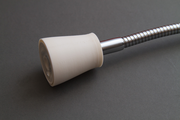
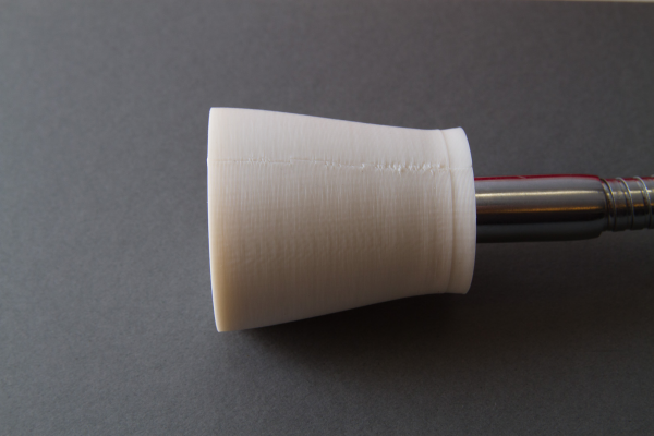
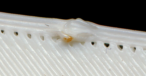
Here's the result so far. The base isn't ready yet. The light bulb fit perfectly on the first print/try. The seam isn't too bad, I used Slic3r prusa edition with the seam option 'rear'. There's no visible layer shifts in the z axis, no z wobble. You can see some interference patterns on the xy plane, this is probably due to the stepper motors rather high torque making individual steps visible. Also the resolution is a bit coarse at 0.32mm per full step. I've said it before but it's such a huge difference compared to my old prusa i3.
It's printed in white ABS. The heat of the light isn't too bad.
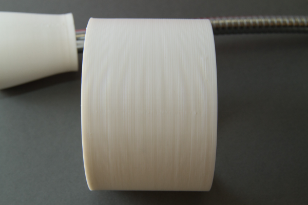
This is comparing a prusa i3 print that I found in my failed prints bin that's cylindrically shaped, roughly comparable to the led light holder. You can see the slight shifts in the layers. With a sharper light you can see also that every other layer seems to be shifted back a bit, most likely caused by the poor M5 leadscrews, even though I used anti backlash things and decoupled the xy motion from the z motion. This was printed at 0.33mm layer height or so, and printed at 40mm/s, I can't remember exactly.
The skimming light (exactly the same as in the previous shot) highlights the interference patterns (which I hope to get rid of using trinamic stepper motor drivers with 256 interpolation microstepping) even more here but the layer to layer shifting is a lot better. The bump on the right was due to a modeling mistake I made, and in the model it's only an 0.15um edge, or 150 nanometers. It's probably exacerbated by the slicer and print resolution. Be aware though that under normal light you can hardly see any irregularities.
I'm pretty happy with the results, it's really nice to put the printer to some actual use
--
Kind regards
Imqqmi
NFAN CoreXY printer:
[reprap.org]
For the led light I've bought a Phillips led bulb spotlight for 12V AC, but also works on 12V DC. It's smallish and not too bright for close up use about 175 lumen IIRC.
The design was made in SolidWorks, to keep my meager modeling skills in form.
Here's the design. I used a pocket for the nut to fit into. The gooseneck ends are already threaded:
It printed pretty well, at 65mm/s for outer perimeters and infill at 83mm/s. It's about 40mm high printed at 0.24 layer height.
Here's the result so far. The base isn't ready yet. The light bulb fit perfectly on the first print/try. The seam isn't too bad, I used Slic3r prusa edition with the seam option 'rear'. There's no visible layer shifts in the z axis, no z wobble. You can see some interference patterns on the xy plane, this is probably due to the stepper motors rather high torque making individual steps visible. Also the resolution is a bit coarse at 0.32mm per full step. I've said it before but it's such a huge difference compared to my old prusa i3.
It's printed in white ABS. The heat of the light isn't too bad.
This is comparing a prusa i3 print that I found in my failed prints bin that's cylindrically shaped, roughly comparable to the led light holder. You can see the slight shifts in the layers. With a sharper light you can see also that every other layer seems to be shifted back a bit, most likely caused by the poor M5 leadscrews, even though I used anti backlash things and decoupled the xy motion from the z motion. This was printed at 0.33mm layer height or so, and printed at 40mm/s, I can't remember exactly.
The skimming light (exactly the same as in the previous shot) highlights the interference patterns (which I hope to get rid of using trinamic stepper motor drivers with 256 interpolation microstepping) even more here but the layer to layer shifting is a lot better. The bump on the right was due to a modeling mistake I made, and in the model it's only an 0.15um edge, or 150 nanometers. It's probably exacerbated by the slicer and print resolution. Be aware though that under normal light you can hardly see any irregularities.
I'm pretty happy with the results, it's really nice to put the printer to some actual use

--
Kind regards
Imqqmi
NFAN CoreXY printer:
[reprap.org]
|
Re: Presenting the NFAN CoreXY 3D printer November 15, 2018 12:52PM |
Registered: 9 years ago Posts: 752 |
Just a quick update. The Duet3D wifi order failed from AlieExpress so I've decided to buy genuine locally, it's now on order. It's not that much more expensive: 120 euro vs 160 euro. I also ordered a couple of e3d socks and nozzles.
I'm looking forward to how the duet will perform vs the RAMPS 1.4 I use now (with Marlin v1.1.9). It's really noisy on moves between 50 and 70mm/s. It's probably in the range of resonance, and the bearings in the v slot wheels can get noisy. The interpolation mode should help with that.
I'll also use 24V instead of 12V for the stepper motors, it'll be interesting how much more speed I can squeeze out of the Nema23 steppers I have.
I've redesigned the e3d v6 hotend holder. It now features a friction fit clip to hold the bowden connector tight. The e3d itself is also held with a friction fit clip, though I've made some holes for a nut and bolt to secure it if it moves. I've also changed from normal m5 nuts to 20x20x5mm flat stock aluminium with a threaded hole in the middle to act as a large surface nut. This allow you to tighten the M5 bolt much more securely. previously there was a lot of play and wobble (especially due to the stiff bowden tube) in the hot end, but not anymore.
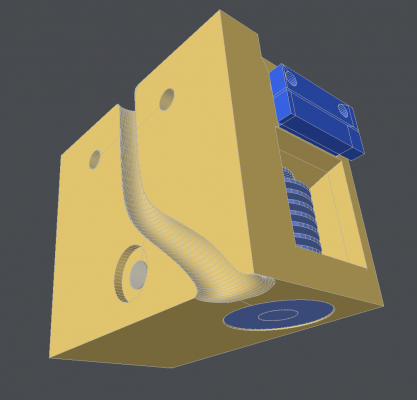
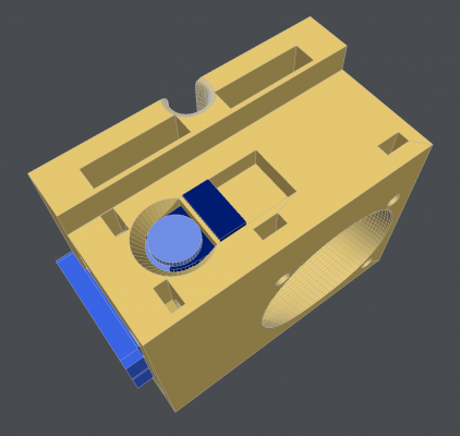
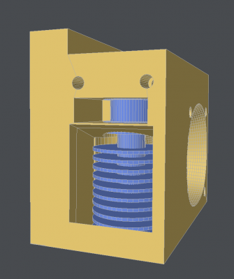
Here are a couple of images of the design:
You can see the duct for the cabling at the back of the part, modeled with an organic shape (NURBS). The lower hole in the lower center is a space for a low profile M5 bolt head. I can screw it into place through the fan duct and with an alan key it can even be accessed through the blades even if a fan is mounted.
In dark blue you see the clip to hold the bowden connector tight. It can slide due to the space cut in the model for easy access. It works a treat! The thin strip of yellow is a support for printing, this is broken away when using the part. It doesn't need support from a slicer at all, it prints as is.
The big slots in the back are where the aluminium 20x20x5mm nut will be placed. No more cracking plastic when tightening it really tight. The part is printed with the fan duct facing upward, for optimum strength.
The e3d cooler part is visible through the fan duct opening and slot for the retaining clip. The duct is shaped to attempt to move the air away from the build platform as not to cool it unintentionally. The e3d cooler is inserted from the bottom sliding all the way up. It's a really tight frictionfit so that the whole e3d part is used to lock it into place for extra stability. My previous design has proven that the abs plastic can stand the heat of the heater block. It does discolor a bit but it doesn't deform.
I also soldered on a connector on the x carriage for the hot end, fan and thermocouple. So far I really like it. I've gone through a few hot end holder revisions and just being able to disconnect it without rewiring the cable chain saves a lot of time and effort. I can also make a laser module with the same connector, I've still got 4 pins for general purpose use so I can wire up a power supply. I think I'll also make a 1.75mm hot end so I can use more specialist filaments that's only available in that size.
All in all I've printed 38 hours with it and no adjustment was needed other than the z offset when I changed the hot end holder. That was one of the main goals of this project.
Next mechanical upgrades are the 5mm aluminium pins I use for the idlers. I've bought 5mm hardened steel smooth pins, aside from cutting to length should be a drop in replacement.
I also want to replace the 6mm belt with a 10mm one I have received. I hope this should reduce some ghosting I've seen at 80mm/s. It's not bad but if I can get rid of it, would be great.
Another upgrade I'm planning is the new e3d high temperature heated beds with the silicone heater pressed on a 6mm tooling plate. I'd like the 300x300mm one (I think 1100W) and a ssr. I wonder if it has phase cutting ability when using PID. It'll be really noisy on the power line if it doesn't. It isn't cheap but it solves the flatness issue I'm having with my MK3 heated bed. It's ok for small prints but shows its uneveness at larger sized prints. And it should heat up in like 60 secs
Once the duet is mounted and cabling is tidied up I'll look into building an enclosure. I think I'm going to use acrylic glass. The ABS part for the hot end holder has warped a bit, going to reprint that once I've got the enclosure done.
The filament drive part (cold end extruder part?) is due for an upgrade. The nylon herringbone gear is printed oval a little and it's not very stiff. I'll try a few ready made designs I've downloaded and got recommended from here. Should be interesting if that should solve the very minor irregular banding you can see when shining a skimming light across the part. This part is one of the few that has survived from my old i3 clone. I might invest in a proper one some time like a e3d titan bowden cold end.
--
Kind regards
Imqqmi
NFAN CoreXY printer:
[reprap.org]
I'm looking forward to how the duet will perform vs the RAMPS 1.4 I use now (with Marlin v1.1.9). It's really noisy on moves between 50 and 70mm/s. It's probably in the range of resonance, and the bearings in the v slot wheels can get noisy. The interpolation mode should help with that.
I'll also use 24V instead of 12V for the stepper motors, it'll be interesting how much more speed I can squeeze out of the Nema23 steppers I have.
I've redesigned the e3d v6 hotend holder. It now features a friction fit clip to hold the bowden connector tight. The e3d itself is also held with a friction fit clip, though I've made some holes for a nut and bolt to secure it if it moves. I've also changed from normal m5 nuts to 20x20x5mm flat stock aluminium with a threaded hole in the middle to act as a large surface nut. This allow you to tighten the M5 bolt much more securely. previously there was a lot of play and wobble (especially due to the stiff bowden tube) in the hot end, but not anymore.
Here are a couple of images of the design:
You can see the duct for the cabling at the back of the part, modeled with an organic shape (NURBS). The lower hole in the lower center is a space for a low profile M5 bolt head. I can screw it into place through the fan duct and with an alan key it can even be accessed through the blades even if a fan is mounted.
In dark blue you see the clip to hold the bowden connector tight. It can slide due to the space cut in the model for easy access. It works a treat! The thin strip of yellow is a support for printing, this is broken away when using the part. It doesn't need support from a slicer at all, it prints as is.
The big slots in the back are where the aluminium 20x20x5mm nut will be placed. No more cracking plastic when tightening it really tight. The part is printed with the fan duct facing upward, for optimum strength.
The e3d cooler part is visible through the fan duct opening and slot for the retaining clip. The duct is shaped to attempt to move the air away from the build platform as not to cool it unintentionally. The e3d cooler is inserted from the bottom sliding all the way up. It's a really tight frictionfit so that the whole e3d part is used to lock it into place for extra stability. My previous design has proven that the abs plastic can stand the heat of the heater block. It does discolor a bit but it doesn't deform.
I also soldered on a connector on the x carriage for the hot end, fan and thermocouple. So far I really like it. I've gone through a few hot end holder revisions and just being able to disconnect it without rewiring the cable chain saves a lot of time and effort. I can also make a laser module with the same connector, I've still got 4 pins for general purpose use so I can wire up a power supply. I think I'll also make a 1.75mm hot end so I can use more specialist filaments that's only available in that size.
All in all I've printed 38 hours with it and no adjustment was needed other than the z offset when I changed the hot end holder. That was one of the main goals of this project.
Next mechanical upgrades are the 5mm aluminium pins I use for the idlers. I've bought 5mm hardened steel smooth pins, aside from cutting to length should be a drop in replacement.
I also want to replace the 6mm belt with a 10mm one I have received. I hope this should reduce some ghosting I've seen at 80mm/s. It's not bad but if I can get rid of it, would be great.
Another upgrade I'm planning is the new e3d high temperature heated beds with the silicone heater pressed on a 6mm tooling plate. I'd like the 300x300mm one (I think 1100W) and a ssr. I wonder if it has phase cutting ability when using PID. It'll be really noisy on the power line if it doesn't. It isn't cheap but it solves the flatness issue I'm having with my MK3 heated bed. It's ok for small prints but shows its uneveness at larger sized prints. And it should heat up in like 60 secs

Once the duet is mounted and cabling is tidied up I'll look into building an enclosure. I think I'm going to use acrylic glass. The ABS part for the hot end holder has warped a bit, going to reprint that once I've got the enclosure done.
The filament drive part (cold end extruder part?) is due for an upgrade. The nylon herringbone gear is printed oval a little and it's not very stiff. I'll try a few ready made designs I've downloaded and got recommended from here. Should be interesting if that should solve the very minor irregular banding you can see when shining a skimming light across the part. This part is one of the few that has survived from my old i3 clone. I might invest in a proper one some time like a e3d titan bowden cold end.
--
Kind regards
Imqqmi
NFAN CoreXY printer:
[reprap.org]
|
Re: Presenting the NFAN CoreXY 3D printer November 18, 2018 01:02PM |
Registered: 9 years ago Posts: 752 |
The Duet 2 wifi has arrived! I've spend the afternoon to replace some connectors from my RAMPS installation to Duet with the included connectors. It's a bit fiddly without a proper crimp tool but I got it done. It was for the limit switches. I went against the consensus of crimping the heated bed and extruder heater by leaving it with tinned ends. It never was a problem before and I made sure I tinned them properly without oxidation. The connectors stay cool.
Setting up the wifi using RealTerm was easy enough, but the board seems to behave weirdly when saving configuration in the web interface. After it reboots the web interface is a couple of seconds to early to try and reconnect and fails. When I manually reconnect it worked. Sometimes the board didn't reset properly, the wifi didn't turn on. I've seen that this issue should be solved by the next release (mine is 2.01 with 1.21 wifi and web interface 1.21.2-dc42).
The worst thing that happened was that the board locked up during saving the config.g file, which resulted in a deleted config.g file, which in turn made it impossible to log into the web interface as some factory defaults seems to be loaded. I had to use the usb lead and Realterm to turn on the wifi, then upload a backup of the config.g (luckily I make backups often!) and it worked again. This happed 3 times now.
The web configurator worked really well. I set it up with corexy and the values I used in marlin which I got using the M503 command. It took me a while to realize that instantDv is the jerk setting in marlin.
Another issue was with setting the Z offset. I've set my homing endstop switch 23.9mm above the nozzle. This means that if I leave the print head above the bed and home it would crash the nozzle into the bed (not a problem, I home the x and y first, which moves the nozzle off the bed). It doesn't appear to be possible to set an offset for the z axis. The x and y M208 worked well, I set the minima to negative values. I also tried tool offset G10 but didn't make a change either, at least not without starting an actual print. When moving the head manually to Z0 it didn't move the nozzle to bed level.
In the end I changed the homeall.g macro, move z to 23.9 and g92 z0 to do the offset manually. It's not a big issue but took me a while to figure out.
The default motor current was way too high for my high torque nema23 motors, at 800mA. It seems strange somehow that 3A motors should need just 200mA that I use now. I can hardly force the motor to skip by holding the x carriage. The printer moves around on the desk instead of skipping steps
At 800mA it was even noisier than with the RAMPS board but at 200mA it's a lot quiter and still powerful enough. It also improved the maximum velocity I can do with it. I haven't experimented with the limits just yet, just wanted to try to get it to print first. But it can do at least double with the duet at 24V what it did with the RAMPS at 12V. Bumped up max velocity from 4800mm/min to 9000mm/min.
The extruder stepper motor is also a lot quieter. It'll be interesting how much I can push the acceleration now. Those TMC2660 are great!
I reversed polarity of the thermocouple giving me negative temperatures heating up the hot end but that was a quick fix.
It got at -100 degrees in 5 seconds. I thought it was due to the reversed polarity but it appears that the 0.5 power factor isn't respected. It's putting the full 24V on the 12V heater cartridge. I like how quickly it heats up from 20 degrees to 258 degrees in like 20 secs! Not sure how long the heater cartridge will last but I'll find out soon enough. I'm going to do the same with the heated bed, using the 12V connections and putting 24V on them with a power factor of 0.75. With the 24V connections used it draws about 6A at 30 degrees and drops to 5A at 90 degrees. The duet can deliver 18A so I'm going to use 24 volts at 75% pwm. I'm aiming for about 12A, leaving just enough for the heater cartridge and stepper motors (psu is rated at 15A).
When the heated bed is at set point temperature it draws about half the power. The stepper motors and heater cartridge are powered after this setpoint is reached.
All in all I'm quite happy with the Duet. Hopefully the board will prove a little more stable during printing than during configuring it.
--
Kind regards
Imqqmi
NFAN CoreXY printer:
[reprap.org]
Setting up the wifi using RealTerm was easy enough, but the board seems to behave weirdly when saving configuration in the web interface. After it reboots the web interface is a couple of seconds to early to try and reconnect and fails. When I manually reconnect it worked. Sometimes the board didn't reset properly, the wifi didn't turn on. I've seen that this issue should be solved by the next release (mine is 2.01 with 1.21 wifi and web interface 1.21.2-dc42).
The worst thing that happened was that the board locked up during saving the config.g file, which resulted in a deleted config.g file, which in turn made it impossible to log into the web interface as some factory defaults seems to be loaded. I had to use the usb lead and Realterm to turn on the wifi, then upload a backup of the config.g (luckily I make backups often!) and it worked again. This happed 3 times now.
The web configurator worked really well. I set it up with corexy and the values I used in marlin which I got using the M503 command. It took me a while to realize that instantDv is the jerk setting in marlin.
Another issue was with setting the Z offset. I've set my homing endstop switch 23.9mm above the nozzle. This means that if I leave the print head above the bed and home it would crash the nozzle into the bed (not a problem, I home the x and y first, which moves the nozzle off the bed). It doesn't appear to be possible to set an offset for the z axis. The x and y M208 worked well, I set the minima to negative values. I also tried tool offset G10 but didn't make a change either, at least not without starting an actual print. When moving the head manually to Z0 it didn't move the nozzle to bed level.
In the end I changed the homeall.g macro, move z to 23.9 and g92 z0 to do the offset manually. It's not a big issue but took me a while to figure out.
The default motor current was way too high for my high torque nema23 motors, at 800mA. It seems strange somehow that 3A motors should need just 200mA that I use now. I can hardly force the motor to skip by holding the x carriage. The printer moves around on the desk instead of skipping steps

At 800mA it was even noisier than with the RAMPS board but at 200mA it's a lot quiter and still powerful enough. It also improved the maximum velocity I can do with it. I haven't experimented with the limits just yet, just wanted to try to get it to print first. But it can do at least double with the duet at 24V what it did with the RAMPS at 12V. Bumped up max velocity from 4800mm/min to 9000mm/min.
The extruder stepper motor is also a lot quieter. It'll be interesting how much I can push the acceleration now. Those TMC2660 are great!
I reversed polarity of the thermocouple giving me negative temperatures heating up the hot end but that was a quick fix.
It got at -100 degrees in 5 seconds. I thought it was due to the reversed polarity but it appears that the 0.5 power factor isn't respected. It's putting the full 24V on the 12V heater cartridge. I like how quickly it heats up from 20 degrees to 258 degrees in like 20 secs! Not sure how long the heater cartridge will last but I'll find out soon enough. I'm going to do the same with the heated bed, using the 12V connections and putting 24V on them with a power factor of 0.75. With the 24V connections used it draws about 6A at 30 degrees and drops to 5A at 90 degrees. The duet can deliver 18A so I'm going to use 24 volts at 75% pwm. I'm aiming for about 12A, leaving just enough for the heater cartridge and stepper motors (psu is rated at 15A).
When the heated bed is at set point temperature it draws about half the power. The stepper motors and heater cartridge are powered after this setpoint is reached.
All in all I'm quite happy with the Duet. Hopefully the board will prove a little more stable during printing than during configuring it.
--
Kind regards
Imqqmi
NFAN CoreXY printer:
[reprap.org]
|
Re: Presenting the NFAN CoreXY 3D printer November 18, 2018 01:25PM |
Registered: 10 years ago Posts: 14,672 |
Hi Imqqmi, I'm glad to hear that you got it all working.
I guess you didn't read [duet3d.dozuki.com], otherwise you would have know that you need to include G92 commands in homez.g and homeall.g right after the G1 S1 Z commands when homing Z using a Z min endstop switch.
That does seem odd. Is it a genuine Duet WiFi, or a clone? If it's a clone then it might have the wrong value current sense resistors.
Even if you set the maximum PWM to 0.5 (which you can do in the M307 command for that heater), you will still get double the power. This is because when you apply 24V to a 12V heater cartridge, it generates four times the heating power (double the voltage and double the current).
HTH David
Large delta printer [miscsolutions.wordpress.com], E3D tool changer, Robotdigg SCARA printer, Crane Quad and Ormerod
Disclosure: I design Duet electronics and work on RepRapFirmware, [duet3d.com].
Quote
imqqmi
Another issue was with setting the Z offset. I've set my homing endstop switch 23.9mm above the nozzle. This means that if I leave the print head above the bed and home it would crash the nozzle into the bed (not a problem, I home the x and y first, which moves the nozzle off the bed). It doesn't appear to be possible to set an offset for the z axis. The x and y M208 worked well, I set the minima to negative values. I also tried tool offset G10 but didn't make a change either, at least not without starting an actual print. When moving the head manually to Z0 it didn't move the nozzle to bed level.
I guess you didn't read [duet3d.dozuki.com], otherwise you would have know that you need to include G92 commands in homez.g and homeall.g right after the G1 S1 Z commands when homing Z using a Z min endstop switch.
Quote
imqqmi
The default motor current was way too high for my high torque nema23 motors, at 800mA. It seems strange somehow that 3A motors should need just 200mA that I use now. I can hardly force the motor to skip by holding the x carriage. The printer moves around on the desk instead of skipping steps
That does seem odd. Is it a genuine Duet WiFi, or a clone? If it's a clone then it might have the wrong value current sense resistors.
Quote
imqqmi
It got at -100 degrees in 5 seconds. I thought it was due to the reversed polarity but it appears that the 0.5 power factor isn't respected. It's putting the full 24V on the 12V heater cartridge.
Even if you set the maximum PWM to 0.5 (which you can do in the M307 command for that heater), you will still get double the power. This is because when you apply 24V to a 12V heater cartridge, it generates four times the heating power (double the voltage and double the current).
HTH David
Large delta printer [miscsolutions.wordpress.com], E3D tool changer, Robotdigg SCARA printer, Crane Quad and Ormerod
Disclosure: I design Duet electronics and work on RepRapFirmware, [duet3d.com].
|
Re: Presenting the NFAN CoreXY 3D printer November 18, 2018 02:52PM |
Registered: 9 years ago Posts: 752 |
Thanks for the feedback!
The homez.g I used was generated, would be great if it would give an option if you enter an offset it would change the homez.g. i'll put in s feature request as Toni suggested.
I bought it from reprapworld.com, a dutch webshop. I assume it's genuine. Are you able to confirm?
What is the extruder pwm frequency? The led doesn't blink like the heated bed one.
Ah yes I remember P=I^2R.
--
Kind regards
Imqqmi
NFAN CoreXY printer:
[reprap.org]
|
Re: Presenting the NFAN CoreXY 3D printer November 18, 2018 03:53PM |
Registered: 10 years ago Posts: 14,672 |
Yes RepRapWorld is a Duet3D reseller.
The default extruder heater PWM frequency is 250Hz. The default bed heater frequency is 10Hz to be compatible with all types of SSR. The PWM frequencies can be changed using the M307 command.
Large delta printer [miscsolutions.wordpress.com], E3D tool changer, Robotdigg SCARA printer, Crane Quad and Ormerod
Disclosure: I design Duet electronics and work on RepRapFirmware, [duet3d.com].
|
Re: Presenting the NFAN CoreXY 3D printer November 19, 2018 11:34AM |
Registered: 9 years ago Posts: 752 |
Thanks David, good to know it's genuine for sure. Got two genuine e3d hot end kits as well as some genuine openbuilds aluminium extrusions in the build.
I've tweaked motor current, for the extruder motor which is a nema17 and is at 800mA. It was skipping steps at 200mA. The Nema23 steppers (AB and Z axis) are at 200mA, no skipped steps so far. The coil resistance is 24 ohms for the nema23 and about 2-3 ohms for the nema17. That might explain the difference.
I've set jerk at 60mm/s from previous 30mm/s which improved the infill around the perimeter boundary.
There's an issue (I think) where the print move goes into a travel move when the next extrusion is very close, like a perimeter. With the prusa slicer edition with hidden seam option it will slice the perimeter and put the seam on a straight piece of the model instead of in the corner. The upshot is that the corners are cleaner, but the mid section gets an ugly seam. I guess this is easier to sand than a corner.
Anyway the issue is that the Duet seems to slow down during the short travel move while in marlin 1.1.9 this doesn't appear to happen.
I've written more about the issue here in the duet forum with example photos:
[forum.duet3d.com]
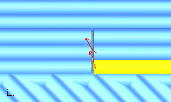
This is a screenshot from repetier host, the perimeter can be seen. The arrows indicate the travel move (the other 'perimeters' is the brim)
Using ramps/marlin this is how it looked, though it was not the same object, the sliced gcode is about the same with hidden seam enabled. The seam bump is negligible about 0.1mm:
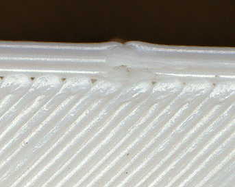
Here's a similar piece of a print with the duet but otherwise exactly the same hardware, the blob sticks out about 0.66mm. This builds up over time, when printing a taller object this can become a much bigger issue as filament starts to build up at this spot:
Hopefully an option to enable jerk for travel moves will be added or another solution can be found.
The extruder power factor has been dialed back to 0.3, it was overshooting 15 degrees giving a heater failure error. Good to know the safeguards are working It still heats up very quickly but overshoots only 8 degrees now. I'll do an autotune soon, to see if that will help reducing it a little more. This effect is also this strong probably because I added an e3d sock to the heater block, reducing the amount of heat it can dissipate.
I got another weird issue that I'm not sure is a mechanical issue or firmware (but likely mechanical). When trying to home one of the stepper motors started to judder, as if only one coil was powered. After fiddling with the wiring and rebooting a couple of times it started to work again. This also happened during a print.
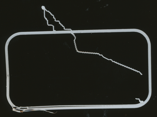
Here's a scan of the first layer. You can see it was printing the brim, then suddenly one stepper motor started to rock back and forth while the other kept going normally. Due to the nature of corexy it can do some weird motions like this, stair casing etc. I'm glad it did it when printing, now I got to see the pattern it made. The loose bit was connected to the inside of the print in the lower right corner. I can't remember this happening with the marlin firmware but I guess due to the move to duet the cabling got routed differently (and is still in the test setup, not the final neatly tidied away cabling). It was almost like the printer had a mind of its own
I've looked up ways to put an external wifi connector on the board and found out that it is possible to replace the wifi module:
[forum.duet3d.com]
I own a hotplate and hot air rework station so it's within my possibility to do but I'm a bit reluctant, don't want to do it unless it's really necessary. I planned to mount the board in a metal case but the wifi signal can't reach the access point that way (faradays cage). I could mount it in a non metal case like acrylic, it would be useful for diagnosing problems to see the leds as well.
It's great to see it print, as hearing it is more difficult now that it's so quiet The nasty resonance at about 50-70mm/s is gone. This also translated in less artifacts on the outer perimeters.
[edit1]
I forgot to mention that I'm impressed the way Duet handles thermistors. It doesn't have thermistor lookup tables like Marlin but a mathematical approach. Enter the known temperature constants/coefficients and resistance and it creates a good representation of the measured temperature. I was prepared to redo my efforts of capturing new ADC values for each temperature in 5 to 10 degrees steps like I did in marlin as none of the lookup tables it had was correct for my thermistor. I also don't know what brand or make the thermistor is, no datasheet.
With the duet I didn't have to do anything, the default value was really close to perfect! With some trial and error I it wouldn't be too hard to get the correct values if it was off.
I still couldn't get rid of the waviness of the outer perimeters. It's worse in the y direction than the x. It's not really ringing, it could be a slight misalignment of the belts or something, when stepper motors aren't entirely in sync or something. It could also be the aluminium pins used for the idlers. I'll try printing a 20x20x2mm slab at 45 degree angle and see how that looks. At 45 degrees the corexy should print the perimeters and move the hot end using a single motor instead of the concerted motion of both. I'll also do a test at slower print speed, 40mm/s instead of 60-80mm per second I usually do to make sure is really isn't ringing. The 45 degree test showed me that indeed most of the waviness is gone. At 40mm per second it's reduced but not gone. Hmmm something to think about
Edited 1 time(s). Last edit at 11/19/2018 12:01PM by imqqmi.
--
Kind regards
Imqqmi
NFAN CoreXY printer:
[reprap.org]
I've tweaked motor current, for the extruder motor which is a nema17 and is at 800mA. It was skipping steps at 200mA. The Nema23 steppers (AB and Z axis) are at 200mA, no skipped steps so far. The coil resistance is 24 ohms for the nema23 and about 2-3 ohms for the nema17. That might explain the difference.
I've set jerk at 60mm/s from previous 30mm/s which improved the infill around the perimeter boundary.
There's an issue (I think) where the print move goes into a travel move when the next extrusion is very close, like a perimeter. With the prusa slicer edition with hidden seam option it will slice the perimeter and put the seam on a straight piece of the model instead of in the corner. The upshot is that the corners are cleaner, but the mid section gets an ugly seam. I guess this is easier to sand than a corner.
Anyway the issue is that the Duet seems to slow down during the short travel move while in marlin 1.1.9 this doesn't appear to happen.
I've written more about the issue here in the duet forum with example photos:
[forum.duet3d.com]
This is a screenshot from repetier host, the perimeter can be seen. The arrows indicate the travel move (the other 'perimeters' is the brim)
Using ramps/marlin this is how it looked, though it was not the same object, the sliced gcode is about the same with hidden seam enabled. The seam bump is negligible about 0.1mm:
Here's a similar piece of a print with the duet but otherwise exactly the same hardware, the blob sticks out about 0.66mm. This builds up over time, when printing a taller object this can become a much bigger issue as filament starts to build up at this spot:
Hopefully an option to enable jerk for travel moves will be added or another solution can be found.
The extruder power factor has been dialed back to 0.3, it was overshooting 15 degrees giving a heater failure error. Good to know the safeguards are working
 It still heats up very quickly but overshoots only 8 degrees now. I'll do an autotune soon, to see if that will help reducing it a little more. This effect is also this strong probably because I added an e3d sock to the heater block, reducing the amount of heat it can dissipate.
 I got another weird issue that I'm not sure is a mechanical issue or firmware (but likely mechanical). When trying to home one of the stepper motors started to judder, as if only one coil was powered. After fiddling with the wiring and rebooting a couple of times it started to work again. This also happened during a print.
Here's a scan of the first layer. You can see it was printing the brim, then suddenly one stepper motor started to rock back and forth while the other kept going normally. Due to the nature of corexy it can do some weird motions like this, stair casing etc. I'm glad it did it when printing, now I got to see the pattern it made. The loose bit was connected to the inside of the print in the lower right corner. I can't remember this happening with the marlin firmware but I guess due to the move to duet the cabling got routed differently (and is still in the test setup, not the final neatly tidied away cabling). It was almost like the printer had a mind of its own

I've looked up ways to put an external wifi connector on the board and found out that it is possible to replace the wifi module:
[forum.duet3d.com]
I own a hotplate and hot air rework station so it's within my possibility to do but I'm a bit reluctant, don't want to do it unless it's really necessary. I planned to mount the board in a metal case but the wifi signal can't reach the access point that way (faradays cage). I could mount it in a non metal case like acrylic, it would be useful for diagnosing problems to see the leds as well.
It's great to see it print, as hearing it is more difficult now that it's so quiet
 The nasty resonance at about 50-70mm/s is gone. This also translated in less artifacts on the outer perimeters.
[edit1]
I forgot to mention that I'm impressed the way Duet handles thermistors. It doesn't have thermistor lookup tables like Marlin but a mathematical approach. Enter the known temperature constants/coefficients and resistance and it creates a good representation of the measured temperature. I was prepared to redo my efforts of capturing new ADC values for each temperature in 5 to 10 degrees steps like I did in marlin as none of the lookup tables it had was correct for my thermistor. I also don't know what brand or make the thermistor is, no datasheet.
With the duet I didn't have to do anything, the default value was really close to perfect! With some trial and error I it wouldn't be too hard to get the correct values if it was off.
I still couldn't get rid of the waviness of the outer perimeters. It's worse in the y direction than the x. It's not really ringing, it could be a slight misalignment of the belts or something, when stepper motors aren't entirely in sync or something. It could also be the aluminium pins used for the idlers. I'll try printing a 20x20x2mm slab at 45 degree angle and see how that looks. At 45 degrees the corexy should print the perimeters and move the hot end using a single motor instead of the concerted motion of both. I'll also do a test at slower print speed, 40mm/s instead of 60-80mm per second I usually do to make sure is really isn't ringing. The 45 degree test showed me that indeed most of the waviness is gone. At 40mm per second it's reduced but not gone. Hmmm something to think about

Edited 1 time(s). Last edit at 11/19/2018 12:01PM by imqqmi.
--
Kind regards
Imqqmi
NFAN CoreXY printer:
[reprap.org]
|
Re: Presenting the NFAN CoreXY 3D printer November 30, 2018 12:32PM |
Registered: 5 years ago Posts: 50 |
I'm dumb so I didn't read the entire thread yet, did you do any of the actual aluminum cutting on your OX? What kind of spindle do you use? I'm building an OX as well and ordered a 500w brushless spindle but I don't really expect doing any metal cutting without implementing flood cooling before because I know milling aluminum is really messy.
|
Re: Presenting the NFAN CoreXY 3D printer November 30, 2018 01:59PM |
Registered: 11 years ago Posts: 5,780 |
Quote
imqqmi
Due to the nature of corexy it can do some weird motions like this, stair casing etc.
What is in the nature of corexy that can cause stair-stepping?
Ultra MegaMax Dominator 3D printer: [drmrehorst.blogspot.com]
|
Re: Presenting the NFAN CoreXY 3D printer November 30, 2018 02:56PM |
Registered: 11 years ago Posts: 1,049 |
|
Re: Presenting the NFAN CoreXY 3D printer December 01, 2018 12:23PM |
Registered: 9 years ago Posts: 752 |
Sure, I'll try to shoot some better video tomorrow.
I did a rough alignment with a bubble level like this:
First I made sure the table was level, then leveled the lower frame section, then the top and the bed frame to get them in the ballpark. I also made sure the 80x20 rails are at 90 degree angle with both bottom and top frame parts.
Then I used a couple of 40x20 beams clamped to the Z bed frame, resting the top part of the Y axis rails on the bed so that it's level with the bed, then fastened the Y rails.
I used shims under the heated bed to further align with the X carriage with a dial indicator mounted (to within about 0.1mm precision in each corner). With a layer height of 0.32mm I can get a good first layer. I'll invest in a better heated bed soon (I'm considering the new E3D high temperature 300x300mmx6mm heated beds which are basically tooling plates with a silicone heater pressed on the back. I hope to achieve a flatter bed that way). One corner of the heated bed is fastened tightly, the others are tight enough that there's no Z motion but not too tight to allow xy expansion. Seems to work quite well. I used 20x30x5mm aluminium flat stock with a 6mm hole and 3mm threaded hole to mount the heated bed.
Edited 1 time(s). Last edit at 12/01/2018 12:27PM by imqqmi.
--
Kind regards
Imqqmi
NFAN CoreXY printer:
[reprap.org]
|
Re: Presenting the NFAN CoreXY 3D printer December 01, 2018 09:05PM |
Registered: 5 years ago Posts: 50 |
|
Re: Presenting the NFAN CoreXY 3D printer December 01, 2018 09:38PM |
Registered: 11 years ago Posts: 5,780 |
I guess it could do that if one of the motors skipped steps, then stepped, then skipped steps, etc. I'm not sure what would cause it to do that, but it looks like it happened in the photo you posted.
Ultra MegaMax Dominator 3D printer: [drmrehorst.blogspot.com]
Ultra MegaMax Dominator 3D printer: [drmrehorst.blogspot.com]
|
Re: Presenting the NFAN CoreXY 3D printer December 06, 2018 01:07PM |
Registered: 9 years ago Posts: 752 |
I guess if one motor is stalling or if a coil gets disconnected somehow the diagonal motion and back and forth motion of the other could cause this. That's my thinking anywayQuote
the_digital_dentist
Quote
imqqmi
Due to the nature of corexy it can do some weird motions like this, stair casing etc.
What is in the nature of corexy that can cause stair-stepping?

--
Kind regards
Imqqmi
NFAN CoreXY printer:
[reprap.org]
|
Re: Presenting the NFAN CoreXY 3D printer December 06, 2018 01:08PM |
Registered: 9 years ago Posts: 752 |
I guess you're right. It just seems it's completely gone crazy when it does it.Quote
the_digital_dentist
I guess it could do that if one of the motors skipped steps, then stepped, then skipped steps, etc. I'm not sure what would cause it to do that, but it looks like it happened in the photo you posted.
--
Kind regards
Imqqmi
NFAN CoreXY printer:
[reprap.org]
|
Re: Presenting the NFAN CoreXY 3D printer March 27, 2019 01:16PM |
Registered: 9 years ago Posts: 752 |
A small update: I've made an enclosure for it using acrylic plates and aluminium angle profiles. The volume of the box is quite large but overall I like it. I still need to plug some holes though.
It has resided on my bench top for a quite a while and got in the way of other projects. I had to find its semi permanent home for it. I decided to put some coaster wheels under it. The 2020 frame quite easily allows me to mount them to the bottom. Now it can be carted under my desk (with a about 50mm/2" to spare). Since the coaster wheels turn the way you push it, it goes wherever I push it. At first I used a couple of straight wheels at the back but that wasn't very practical. Whenever I'm using it I can easily move it from under the desk, turn it around for a filament swap and start printing. When done it can be easily rolled back to its storage position and out of the way. An added bonus is that I can now clean the floor under the 3D printer. I had a furniture shelf plate under it and at first intended to mount it to it and place the coaster wheels under that but it wouldn't fit under the desk. Now it's open at the bottom for now. I'll make an acrylic plate for the bottom.
To mount the wheels I had to put the 3D printer on its side, but that wasn't a problem, and no adjustments were needed when the coaster wheels were in place
To get a better view of the print, I've added a small LED bulb to the front of the printer at about the same level as the bed (or slightly higher so it shines over the current layer that's printed, the bed lowers at every new layer). This way I can clearly see artifacts while its printing. I've used a buck converter to power the LED bulb and 3D printed an armature for it.
I've removed the 12V PSU (I had a 24V and 12V PSU in use) and used the buck converter to get 12V from 24V. It now powers the 40x40mm hot end heat break cooler and the LED bulb. It's a velleman VMA404, it doesn't appear to get hot.
I've added 24V 2000rpm fans that can be controlled by the duet. I've mounted these to the front and back of the frame and offset them so they don't blow against each other. This is my solution to the part cooling fans. I wanted them off the hot end assembly to save weight. So far it seems to work well to cool printing small parts. Especially for printing small TPC flex filament. Without the fans it prints a gooey mess. Now the prints come out very nice!
I can use them also to cool the print/bed after printing is done and the top cover is open. It can also be used to move the heat from the heated bed to the chamber before printing. I do plan to add a separate chamber heater though.
In a local shop I've found some build tack print surfaces and stuck it to a glass plate.It really works well with PLA, ABS, PETG and TPC flex filament. Especially the latter is very useful to me, as I had to use vinyl stuck to glass as other print surfaces didn't seem to work.
I've found a local dealer selling tooling plates. Hopefully they will do business with a consumer. I'll order a larger plate and mill it to size on the CNC. I've seen that a swiss company also sells toolingplates for the bed but it seems forever out of stock. It's got a pocket milled out to fit a silicone heater. I could do something similar although it will take a long time to mill out such a large area. The tooling plate is either EN AC 5083 or EN AC 7021. The 5083 is more form stable when heated, I think I'll go with that. The aluminium alloy is suitable for milling, unlike the aluminium plates I used for the NFAN parts.
I'm starting to get orders for printing my floppy cleaning kit, so it'll see some useful action
--
Kind regards
Imqqmi
NFAN CoreXY printer:
[reprap.org]
It has resided on my bench top for a quite a while and got in the way of other projects. I had to find its semi permanent home for it. I decided to put some coaster wheels under it. The 2020 frame quite easily allows me to mount them to the bottom. Now it can be carted under my desk (with a about 50mm/2" to spare). Since the coaster wheels turn the way you push it, it goes wherever I push it. At first I used a couple of straight wheels at the back but that wasn't very practical. Whenever I'm using it I can easily move it from under the desk, turn it around for a filament swap and start printing. When done it can be easily rolled back to its storage position and out of the way. An added bonus is that I can now clean the floor under the 3D printer. I had a furniture shelf plate under it and at first intended to mount it to it and place the coaster wheels under that but it wouldn't fit under the desk. Now it's open at the bottom for now. I'll make an acrylic plate for the bottom.
To mount the wheels I had to put the 3D printer on its side, but that wasn't a problem, and no adjustments were needed when the coaster wheels were in place

To get a better view of the print, I've added a small LED bulb to the front of the printer at about the same level as the bed (or slightly higher so it shines over the current layer that's printed, the bed lowers at every new layer). This way I can clearly see artifacts while its printing. I've used a buck converter to power the LED bulb and 3D printed an armature for it.
I've removed the 12V PSU (I had a 24V and 12V PSU in use) and used the buck converter to get 12V from 24V. It now powers the 40x40mm hot end heat break cooler and the LED bulb. It's a velleman VMA404, it doesn't appear to get hot.
I've added 24V 2000rpm fans that can be controlled by the duet. I've mounted these to the front and back of the frame and offset them so they don't blow against each other. This is my solution to the part cooling fans. I wanted them off the hot end assembly to save weight. So far it seems to work well to cool printing small parts. Especially for printing small TPC flex filament. Without the fans it prints a gooey mess. Now the prints come out very nice!
I can use them also to cool the print/bed after printing is done and the top cover is open. It can also be used to move the heat from the heated bed to the chamber before printing. I do plan to add a separate chamber heater though.
In a local shop I've found some build tack print surfaces and stuck it to a glass plate.It really works well with PLA, ABS, PETG and TPC flex filament. Especially the latter is very useful to me, as I had to use vinyl stuck to glass as other print surfaces didn't seem to work.
I've found a local dealer selling tooling plates. Hopefully they will do business with a consumer. I'll order a larger plate and mill it to size on the CNC. I've seen that a swiss company also sells toolingplates for the bed but it seems forever out of stock. It's got a pocket milled out to fit a silicone heater. I could do something similar although it will take a long time to mill out such a large area. The tooling plate is either EN AC 5083 or EN AC 7021. The 5083 is more form stable when heated, I think I'll go with that. The aluminium alloy is suitable for milling, unlike the aluminium plates I used for the NFAN parts.
I'm starting to get orders for printing my floppy cleaning kit, so it'll see some useful action

--
Kind regards
Imqqmi
NFAN CoreXY printer:
[reprap.org]
|
Re: Presenting the NFAN CoreXY 3D printer March 27, 2019 02:20PM |
Registered: 11 years ago Posts: 5,780 |
Why do you need to mill a pocket into the plate for the heater?
Ultra MegaMax Dominator 3D printer: [drmrehorst.blogspot.com]
Ultra MegaMax Dominator 3D printer: [drmrehorst.blogspot.com]
|
Re: Presenting the NFAN CoreXY 3D printer April 13, 2019 03:42PM |
Registered: 9 years ago Posts: 752 |
Maybe to save some space, but I think I'm not going to do it, I've got plenty of space. The C250 aluminium tooling plates have arrived, looks good! I've ordered enough for 4 bed plates, though the rest I'm probably going to use to mill out the bed brackets, properly this time. I've milled out 350x350mm bed plate and drilled countersink holes. The plate is quite heavy, the z axis stepper motor had problems maintaining the 1440mm/min speed, dropped it down to 1000mm/min and upped the motor current. It's a bit noisier now.
I've ordered a 750W 230V silicone heater and SSR from Keenovo. I'll try mounting it at 3 points, though the way I've setup the z axis frame doesn't really allow for a centre mounting point. I'll refresh my memory with the kinematic mounting from your build Mark. I've been thinking to use a machined part that has a circular ramp to adjust the bed alignment. I'll use some shims in the mean time. I'll design a proper mount for the dial indicator so I can measure the bed level in more detail.
I've moved the z home end stop switch to a different location, it was interfering with the z lead screw. Luckily with the 2020 extrusions it was easy to do.
The buildtak plate system looks nice, has anyone experience with them? I'm using a buildtak surface to print on (the MK3 200x200mm heated bed with glass plates) and so far works well for me.
--
Kind regards
Imqqmi
NFAN CoreXY printer:
[reprap.org]
|
Re: Presenting the NFAN CoreXY 3D printer April 13, 2019 04:54PM |
Registered: 11 years ago Posts: 5,780 |
I just happened to look at your video with the steel core belts. The belt paths don't look right in the video. It looks like the belt segments between the motors and the pulleys on the X axis are not parallel to the guide rails. That's going to cause distorted prints and maybe some other problems. See: [drmrehorst.blogspot.com]
In your youtube comments you said the "belt slips out of the teeth", which is one of the other problems that bad belt routing can cause. That would indicate that the tension on the belts is not constant regardless of extruder carriage position. If the belt path routing is bad, the tension will vary with the extruder carriage position. In some positions it will be very tight and in others it may get so loose that the motor can spin without moving the belt.
Edited 1 time(s). Last edit at 04/13/2019 05:00PM by the_digital_dentist.
Ultra MegaMax Dominator 3D printer: [drmrehorst.blogspot.com]
|
Re: Presenting the NFAN CoreXY 3D printer April 13, 2019 05:22PM |
Registered: 9 years ago Posts: 752 |
Thanks for the comments. I've since moved on to glass core belts, those don't slip and can bend around smaller radiusses. The PU steel belts really need bigger radius pulleys. A smaller radius will pinch the belt teeth, resulting in smaller tooth spacing, making them slip over the teeth of the pulleys.
I've paid special care as per your instructions so that the right segments are parallel, maybe the alignment on the steel belt footage wasn't in alignment but it is now, I think . I should shoot some new footage.
--
Kind regards
Imqqmi
NFAN CoreXY printer:
[reprap.org]
I've paid special care as per your instructions so that the right segments are parallel, maybe the alignment on the steel belt footage wasn't in alignment but it is now, I think
 . I should shoot some new footage.
--
Kind regards
Imqqmi
NFAN CoreXY printer:
[reprap.org]
Sorry, only registered users may post in this forum.
