corexy question
Posted by build3r
|
corexy question January 27, 2019 06:30AM |
Registered: 5 years ago Posts: 7 |
As a first project, I would like to build a large (1m x 1m) plotter / laser cutter. The idea is to get familiar with all kind of topics before I begin my build of a 3D printer. Also, I have some actual use for this device.
Now to the coreXY mechanism: It seems to me that the belts keeps X and Y axis orthogonal (given that the pulleys are at the right place and firmly anchored).
My question: Is it correct that because of that the carriage could actually be "floating" between guides that prevent it from moving laterally, i.e. that I don't need a fixed 90° fixture to the lateral fixed guides? I understand that such a 90 degree fixture could bring additional dynamic stability, but couldn't it also lead to binding?
If that is true and not having a rigid 90° fixture does not have several practical disadvantages, this would make the design of this large thing much easier and the structure more lightweight.
|
Re: corexy question January 27, 2019 10:30AM |
Registered: 9 years ago Posts: 76 |
I don't understand the question. What do you mean by "floating?" All four end-points of the belts are fixed to the carriage so I cannot see where "floating" might come in. Well, unless the carriage is made of TPU! 
Are you confusing the CoreXY belt layout with an H-Bot? That can and almost certainly will float or bind unless you have a very, very, very rigid setup.
Edited 1 time(s). Last edit at 01/27/2019 10:31AM by StlLooking.

Are you confusing the CoreXY belt layout with an H-Bot? That can and almost certainly will float or bind unless you have a very, very, very rigid setup.
Edited 1 time(s). Last edit at 01/27/2019 10:31AM by StlLooking.
|
Re: corexy question January 27, 2019 11:42AM |
Registered: 11 years ago Posts: 5,780 |
Have you ever used or built a 3D printer before? As a first project a 1m x 1m machine is extremely ambitious. Dual use as a laser cutter adds another level of complication. Many people don't realize that a lasers cut by burning which results in fumes and smoke that need to be ventilated outdoors. You simply can't use a laser cutter indoors without a ventilation system. The risk of a fire is much greater with a laser cutter than a 3D printer, so you have to take appropriate precautions.
The corexy mechanism is kept square by the belt tension. Even if you fix the X axis guide rail to the Y axis bearings at a rigid 90 degrees, the X axis rail(s) will flex. It sounds like you're asking if an X axis guide rail is even necessary. Yes, it is. The extruder carriage has mass and has cables and filament going to it. Without a guide rail of some sort it will flop around on the belts. The X axis guide rail is there to stabilize the extruder carriage and make sure it moves only as commanded.
There is always flex in the X axis, especially over a distance of 1m, that will allow it to get out of square with the Y axis until you tension the belts. In a practical 1m x 1m machine, there will probably be some flex in the Y axis too.
I suggest you start with a smaller design and once you understand how it works, look at building something bigger, if you still think you must. 1m x 1m prints take a long time to finish. If you want to go with thick layers and wide lines using a large nozzle, you'll find there are all sorts of extrusion problems that don't happen with smaller nozzles.
Ultra MegaMax Dominator 3D printer: [drmrehorst.blogspot.com]
|
Re: corexy question January 27, 2019 04:28PM |
Registered: 5 years ago Posts: 7 |
Quote
the_digital_dentist
Have you ever used or built a 3D printer before? As a first project a 1m x 1m machine is extremely ambitious. Dual use as a laser cutter adds another level of complication.
Thanks for your thoughts and the warning. Yes, I have a 3D printer I built from a kit. What I actually want to build is not a 3D printer, but a plotter (with a pen) that can also cut paper or thin fabric (no PVC or halogenated stuff). It will certainly have ventilation. There will only be a simple Z mechanism to lift the pen, so it's kind of 2.5D. It also does not have to be fast, and resolution requirements are far below the ones for a 3D printer.
Quote
the_digital_dentist
The corexy mechanism is kept square by the belt tension. Even if you fix the X axis guide rail to the Y axis bearings at a rigid 90 degrees, the X axis rail(s) will flex.
That is exactly what I wanted to know.
Quote
the_digital_dentist
It sounds like you're asking if an X axis guide rail is even necessary. Yes, it is. The extruder carriage has mass and has cables and filament going to it. Without a guide rail of some sort it will flop around on the belts. The X axis guide rail is there to stabilize the extruder carriage and make sure it moves only as commanded.
I guess my question was not clear. I was interested in whether the X axis needed to be connected at a rigid 90° with one or both Y rails, or whether the belt tensions would do the job. In my application, the two Y axis will be fixed to a table at several locations, so flex will be limited. My idea was that the X axis could possibly run on wheels (horizontal ones) that keep it between the two Y rails, preventing unintended (not belt driven) lateral movement in X direction. It seems the answer to that is yes.
|
Re: corexy question January 27, 2019 04:33PM |
Registered: 5 years ago Posts: 7 |
Quote
StlLooking
I don't understand the question. What do you mean by "floating?" All four end-points of the belts are fixed to the carriage so I cannot see where "floating" might come in. Well, unless the carriage is made of TPU!
:-) With "floating" I meant with no fixed connection of the X axis to the two Y rails. Specifically, I thought on running it on wheels (vertical ones that run either on the table or the Y rails, and horizontal ones that guide it along the inside of the Y rails (by "rail" I mean these parts of the frame, not a proper linear rail).
Does that make sense?
|
Re: corexy question January 27, 2019 05:36PM |
Registered: 11 years ago Posts: 5,780 |
I guess it all depends on the precision and accuracy you require.
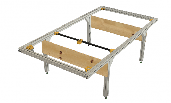
I built a corexy sand table in which the ends of the X axis simply slide in the slots of the t-slot frame on UHMW bearings. A sand table is a relatively low resolution mechanism so I didn't need the precision that would come from more complex construction. The X axis consists of a 16mm square aluminum tube with pulley blocks on the ends. The length of the tube was cut to fit into the pulley blocks and between the two Y axis frame rails. The X axis assembly can wobble between the Y axis rails about 0.5 mm or so. It is kept square to the Y axis entirely by belt tension. The table is about 2m x 1m and the Y rails are only joined at the ends, and at the legs where there are plywood cross-members stiffening the legs.
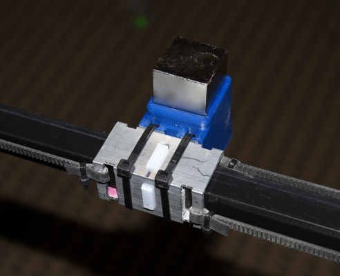
This is the magnet carriage- a 1" square tube that fits over the 16mm square tube with UHMW bearings between the two.
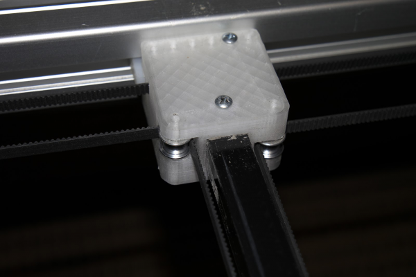
This is one of the pulley blocks on the ends of the X axis. You can just see the end of the UHMW bearing the goes into the Y axis frame slot at the back. The slot is 10mm wide and the bearing block is probably 9.5mm thick, so there's some slop in that fit, too, which again doesn't matter in this application.
Ultra MegaMax Dominator 3D printer: [drmrehorst.blogspot.com]
|
Re: corexy question January 29, 2019 02:48PM |
Registered: 5 years ago Posts: 7 |
Thanks, this is more or less what I had thought about.
I think I will use some sort of rail on one side to prevent the wobble between the axis, and a PTFE or POM guide as you used it with the sand table. I am not so much concerned about absolute positioning accuracy, but more about repeatability (for example, when plotting a circle, start and end point should be as close as possible).
I think I will use some sort of rail on one side to prevent the wobble between the axis, and a PTFE or POM guide as you used it with the sand table. I am not so much concerned about absolute positioning accuracy, but more about repeatability (for example, when plotting a circle, start and end point should be as close as possible).
Sorry, only registered users may post in this forum.


