CaffeineXY
Posted by AxeSlash
|
CaffeineXY February 04, 2020 04:49PM |
Registered: 4 years ago Posts: 7 |
First time poster, long time lurker (ish).
Been printing for about 2 years, and like to design and make stuff, so after deciding that I've had enough of my chinesium printers it's time to make something a bit more serious.
The design work on this has been powered almost exclusively by caffeine consumption, hence the name. I may come up with something more epic-sounding at a later date.
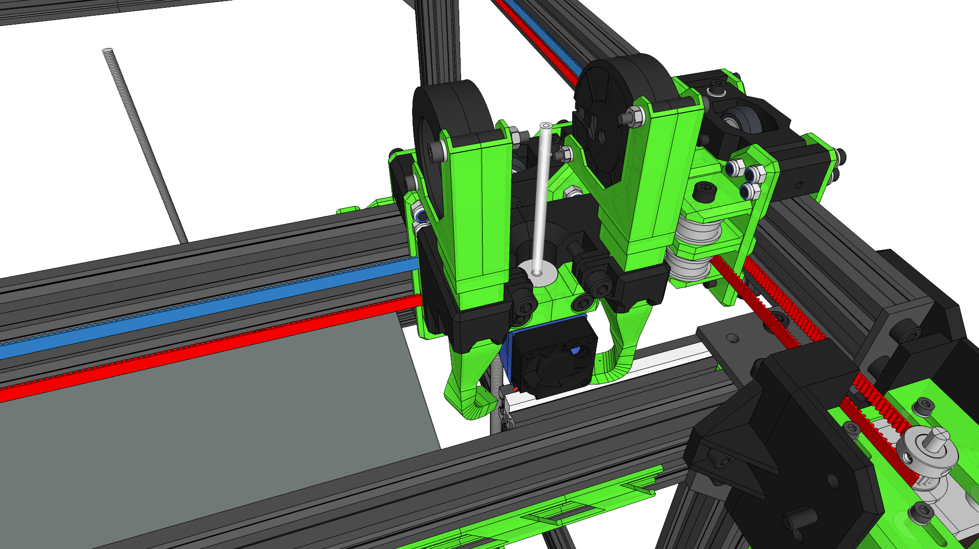
So here's the deal: after doing a lot of homework (read: stealing ideas from Deckingman and Digital Dentist's blogs and videos posts amongst others), I came up with this design - still in progress (drawings are still somewhat incomplete/lazily put together, but you get the idea):
1. D'ya reckon I will need internal corners as well as the external plates for the main frame?
2. I know my build surface is somewhat unorthodox in the way it's clamped. Just a bolt at the back through the ali tooling plate and two ears at the front to hold the glass and the rest of the stuff together (nothing is glued together), any input on that would be good.
All comments are welcome, I'm here to learn.
Edited 4 time(s). Last edit at 02/04/2020 05:08PM by AxeSlash.
Been printing for about 2 years, and like to design and make stuff, so after deciding that I've had enough of my chinesium printers it's time to make something a bit more serious.
The design work on this has been powered almost exclusively by caffeine consumption, hence the name. I may come up with something more epic-sounding at a later date.
So here's the deal: after doing a lot of homework (read: stealing ideas from Deckingman and Digital Dentist's blogs and videos posts amongst others), I came up with this design - still in progress (drawings are still somewhat incomplete/lazily put together, but you get the idea):
- Distantly based on a D-Bot
- 400mm x 400mm x 400mm build volume
- Bowden, but with extruder & motor mounted on gimbal to reduce bowden length without kinking
- 3 lead screws (@2mm lead) belted off 1 NEMA17 motor with 1:2 reduction (20T/40T pulleys)
- Probably 1.8deg motors all round but haven't done the maths yet to see if there's enough advantage to 0.9s.
- 2040 and 4040 V-Slot outer frame and X axis. Bed is currently 2020.
- 400mm x 400mm 1400W Keenovo silicone heat bed with cork insulation
- 420mm x 400mm ali tooling plate for bed
- Print surface easily removable - so a) I can take a finished print out to cool down quicker, and b) easier to swap out to different surface materials. Gonna start with 6mm glass; the bottom of the bed is a 6mm polypropylene sheet (just to keep the cork in place), so I can swap that with the glass to see if printing on PP is any better. EDIT: That said, having just looked up PP's horrendous coefficient of thermal expansion (~+4-5mm over 400mm when heated from 20C to 100C, ouch!) I might pick another material for that. FR4, probably.
- Printed parts will be printed in PETG (mostly transparent green for bling purposes) for now, maybe upgraded to something better once it's running
- Dual 5015 cooling fans on a duct designed from HVAC principles
- E3D V6 hot end (probably all metal) with room for upgrading to Volcano if I discover I need it
- Silicone nozzle wipe strip
- 6mm GT2 belts, hopefully Gates if I can find them at a sensible price without running foul of their minimum order
- Printed structural parts kept to a minimum where possible within my means (I'm not on a tight budget but I'm not about to shell out cash to get stuff CNC'd. Yet. Maybe once my caffeine consumption has decreased and the damn thing is built. Maybe I'll move on to building a mill or something...)
- Duet 2 control board unless anyone thinks there is a real advantage to going up to a Duet 3 for this machine?
- F635ZZ bearings for all idlers. Finding good toothed idlers at a price that doesn't offend me seemed difficult.
- All belts parallel and not twisted/crossed. I know doing that works for some people, but I decided I'd rather just use larger idlers instead.
- Where possible everything is designed to be easily dismantlable (no glued parts, no hidden bolts etc) so I can experiment with the design more easily. I absolute abhor having to take out 6 bolts just to undo 2 bolts underneath. It's a personal hatred.
- Designed to be reasonably easy to enclose at a later date, although that's a lower design priority than everything else
1. D'ya reckon I will need internal corners as well as the external plates for the main frame?
2. I know my build surface is somewhat unorthodox in the way it's clamped. Just a bolt at the back through the ali tooling plate and two ears at the front to hold the glass and the rest of the stuff together (nothing is glued together), any input on that would be good.
All comments are welcome, I'm here to learn.
Edited 4 time(s). Last edit at 02/04/2020 05:08PM by AxeSlash.
|
Re: CaffeineXY February 04, 2020 08:45PM |
Registered: 11 years ago Posts: 5,780 |
Using a Bowden type extruder will prevent printing with flexible filament. TPU is a great material to print and once you use it you'll find a lot of uses for it. It's easy to print, sticks to bed surfaces well, doesn't stink, and is tough as nails.
An open, unheated machine will limit materials choices, too. You won't be printing much ABS without a warm enclosure.
The aluminum bed plate is going to expand by about 0.7 mm when heated.
You'd get more benefit from adding side panels than from a bunch of aluminum corner brackets. Side panels protect prints from air movement and add a lot of rigidity to the frame. Once you have side panels, full enclosure is just a matter of adding top and bottom panels.
Ultra MegaMax Dominator 3D printer: [drmrehorst.blogspot.com]
|
Re: CaffeineXY February 05, 2020 10:02AM |
Registered: 4 years ago Posts: 7 |
Yeah I'm not too fussed about flexibles tbh. I have a long list of stuff to print, none of which requires flexibility. If I do decide to go that route I'll put together a direct drive carriage.
And this machine will be enclosed eventually, but for the immediate future it's mainly PLA and PETG that I'll be printing. Nylon & PC later down the line, but at the moment acrylic panels push my budget over the edge. I'd also want the panels to be easily removable, so I want the frame to be structurally sound on it's own without relying on the strength of the panels.
And, having read your blog, I've accounted for the bed plate expanding. It's only properly secured by the single bolt at the back - the clamps near the front should flex enough to allow 0.7mm of expansion.
|
Re: CaffeineXY February 05, 2020 12:44PM |
Registered: 11 years ago Posts: 5,780 |
PC is a better choice for side panels when the time comes. Acrylic cracks easily under the stress of bolts- that's why you don't see many acrylic frame 3D printers for sale any more.
Ultra MegaMax Dominator 3D printer: [drmrehorst.blogspot.com]
Ultra MegaMax Dominator 3D printer: [drmrehorst.blogspot.com]
|
Re: CaffeineXY February 21, 2020 06:23PM |
Registered: 4 years ago Posts: 7 |
Currently looking into wiring. Any thoughts on this wiring diagram?
I'm considering running a CAT5 to the X carriage and making some sort of breakout board to separate Dupont connectors there. Probably for the fans, end stop, and thermistor. Then maybe a second CAT5 (with some of the cores doubled up) for heater & BLTouch. Stranded CAT5 all round.
Is it better to wire the fan for the Duet & SSR into a fan output on the Duet, or wire it directly into a 24V output on the PSU?
Thanks
Edited 1 time(s). Last edit at 02/21/2020 06:38PM by AxeSlash.
|
Re: CaffeineXY February 22, 2020 12:25AM |
Registered: 11 years ago Posts: 5,780 |
The SSR probably won't need a fan if it is mounted on the printer's aluminum frame. You can save a couple wires to the extruder carriage by mounting the X axis endstop on the printer's frame. It will only be able to home X immediately after it homes Y, but I have found that there's really no need to home X independently. A couple simple changes to the homing config files are all that's required.
I like to use separate connectors for each item on the extruder carriage. It makes it easy to make changes or repairs without having to take everything apart. I also eschew "professional" looking plastic covers because they are a PITA to remove and replace when working on the extruder or hot-end. I do a lot of swapping of parts there.
I haven't used cat5 cable for wiring. I prefer to twist pairs of appropriate gauge wires myself. I use an electric drill to do the twisting.
Ultra MegaMax Dominator 3D printer: [drmrehorst.blogspot.com]
Sorry, only registered users may post in this forum.