Z Axis Design Help
Posted by naps1saps
|
Z Axis Design Help March 02, 2020 11:51AM |
Registered: 8 years ago Posts: 16 |
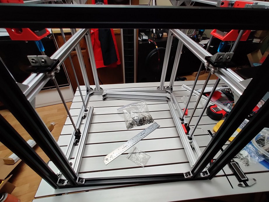
I've designed my own Core XY and finally got to the part where I put together the Z axis bed supports, etc.
The cube is 500mm^3 with a print bed area of up to 300x300mm
I'm using two 8mm threaded rods on either side and four 8mm smooth rods on each corner with a single LM8UU
It seemed smooth until I attached the bed support to the threaded rod. The bed support deflects a bit pushing on the corners and they bind going up and down slightly causing no movement for 1mm then a corner lurches.
I need a different solution :\
* Would it be any better to use a single LM8LUU or two stacked LM8UU? I don't really want to take away from my Z volume spacing them out.
* Would IGUS bushings work any better? Is the deflection worse?
* I'm also wondering if keeping the same setup but replacing one of the rods with a passive belt driven threaded rod would be better?
Edited 1 time(s). Last edit at 03/02/2020 11:54AM by naps1saps.
|
Re: Z Axis Design Help March 02, 2020 05:08PM |
Registered: 11 years ago Posts: 5,780 |
You really only need two rails to provide the vertical guidance. Adding more increases the chances of them being misaligned with the exact results you are experiencing.
It's is generally best to put the guide rails as close to the screws as possible. For maximum stability, 3 screws to do the lifting is best. You will have to decide if you want to use separate motors and auto tramming (so you can make impressive videos) or simply drive all three screws with one motor and a loop belt (so you can just print).
Pictures?
Ultra MegaMax Dominator 3D printer: [drmrehorst.blogspot.com]
|
Re: Z Axis Design Help March 02, 2020 05:15PM |
Registered: 8 years ago Posts: 16 |
Amazon had 8 IGUS bushings with free 1 day shipping for $11 which is pretty close to what they cost from Aliexpress. I ordered a pack and will give them a try and then maybe design and print a dual bushing holder if that still doesn't do the trick and use the extras.
Ultimately using 3 threaded rods should provide a more stable platform so I might change over to that if this doesn't work well enough or when things start wearing out.
Ultimately using 3 threaded rods should provide a more stable platform so I might change over to that if this doesn't work well enough or when things start wearing out.
|
Re: Z Axis Design Help March 02, 2020 05:20PM |
Registered: 8 years ago Posts: 16 |
I'll post a picture when I get home from work.
I have the rods all the way at the corners so I'll give it a try closer to the screw but I'm sure it will make the bed deflection worse then again nothing pushes on it while printing except during head crashes.
If I end up doing triple screws:
Since the driver board only has a header for one motor and I have to solder on another header, I would do a belt synchronized one motor dual screw on one side and a single on the other.
|
Re: Z Axis Design Help March 02, 2020 08:06PM |
Registered: 11 years ago Posts: 5,780 |
The problem with using multiple motors in the Z axis is that the motors jump every time the machine is powered up. You don't know exactly how far they're going to jump or in which direction. That means the bed will tilt. You'll have to resync the motors/screws frequently. You can do that by running the bed to the bottom of the Z axis and hitting the mechanical stops. That will force the screws back into sync as long as you set up the stops so that the bed is trammed when it hits them.
Bushings aren't going to solve the binding/walking problem. The problem is that the 4 guide rails are not parallel. It can be hard to get two end-supported rails into a parallel relationship. It gets harder with each rail you add.
Ultra MegaMax Dominator 3D printer: [drmrehorst.blogspot.com]
Bushings aren't going to solve the binding/walking problem. The problem is that the 4 guide rails are not parallel. It can be hard to get two end-supported rails into a parallel relationship. It gets harder with each rail you add.
Ultra MegaMax Dominator 3D printer: [drmrehorst.blogspot.com]
|
Re: Z Axis Design Help March 03, 2020 05:08PM |
Registered: 8 years ago Posts: 16 |
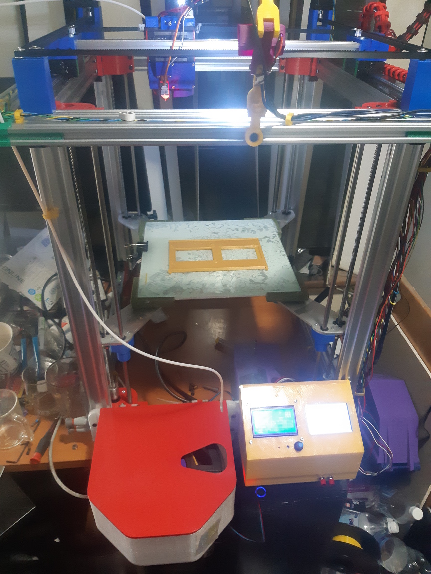
I moved the rods closer to the screw and that produced the expected result. Picture attached. The walking/woble effect has been eliminated.
I don't expect to have issues with dual z since I haven't had any with my i3 clone after 5 years. It will be a new board though.
I don't expect to have issues with dual z since I haven't had any with my i3 clone after 5 years. It will be a new board though.
|
Re: Z Axis Design Help March 04, 2020 12:20PM |
Registered: 8 years ago Posts: 16 |
The IGUS bearings are way nicer than those cheap ball bearing ones. It was definitely worth $11 Seems to allow less deflection and at the same time no binding when they are out of alignment.
I'm just curious how much bed deflection is normal for a dual screw? I'm getting about 3-4mm at the edge when I push down on the unsupported sides.
I'm just curious how much bed deflection is normal for a dual screw? I'm getting about 3-4mm at the edge when I push down on the unsupported sides.
|
Re: Z Axis Design Help March 04, 2020 02:42PM |
Registered: 11 years ago Posts: 5,780 |
That seems like a lot, but I guess it depends on how hard you're pushing on it. What matters most is how much it bounces when you're printing.
Ultra MegaMax Dominator 3D printer: [drmrehorst.blogspot.com]
Ultra MegaMax Dominator 3D printer: [drmrehorst.blogspot.com]
|
Re: Z Axis Design Help May 24, 2020 05:03PM |
Registered: 9 years ago Posts: 294 |
I can't imagine getting 2 screws and 4 rods all parallel at the same time. I had a bear of a time just getting my 3 screws parallel, and they only run about 300mm.
My lateral movement is constrained by single wheels on each corner running in the v grove of my rails. It looks too simple to work but it does work very effectively.
My lateral movement is constrained by single wheels on each corner running in the v grove of my rails. It looks too simple to work but it does work very effectively.
|
Re: Z Axis Design Help October 15, 2020 10:28AM |
Registered: 7 years ago Posts: 24 |
Just to prove it can be done, my Printer uses 4 Z axis motors, and the experimental 4 point levelling system, Waiting on InsanityAutomation on the marlin git hub to fixes the issues I Identified, but I have it working on my printer. Please see picture attached
|
Re: Z Axis Design Help October 15, 2020 11:42AM |
Registered: 3 years ago Posts: 29 |
Geometrically, 3 points define a plane, not 4. There is a basic physical problem with 4 point (4 dimension) leveling on a 3 dimension build plate. Picture this: (Using compass points for placement) points 1(N) is your ref point. Points 2(E), 3(W), and 4(S) are high. To adjust this you must simultaneously lower 2, 3, and 4, OR simultaneously raise 1 and lower 4. If you do not do it simultaneously, you will either cause nothing to happen or bend your build plate into 4 dimensions. With a 3 point leveling system, you are adjusting a 3 dimension object and only one point needs to be adjusted at a time.
On my plate, I have one screw fixed and adjust the other 2 individually. The original plan for my printer (Carl Feniak's build) had 4 adjusters. When I adjusted them with a very rigid build plate, the result was to distort the supporting frame resulting in no movement of the build plate.
Edited 1 time(s). Last edit at 10/15/2020 11:59AM by dustinoff.
|
Re: Z Axis Design Help October 16, 2020 09:01AM |
Registered: 7 years ago Posts: 24 |
Quote
dustinoff
Geometrically, 3 points define a plane, not 4. There is a basic physical problem with 4 point (4 dimension) leveling on a 3 dimension build plate. Picture this: (Using compass points for placement) points 1(N) is your ref point. Points 2(E), 3(W), and 4(S) are high. To adjust this you must simultaneously lower 2, 3, and 4, OR simultaneously raise 1 and lower 4. If you do not do it simultaneously, you will either cause nothing to happen or bend your build plate into 4 dimensions. With a 3 point leveling system, you are adjusting a 3 dimension object and only one point needs to be adjusted at a time.
On my plate, I have one screw fixed and adjust the other 2 individually. The original plan for my printer (Carl Feniak's build) had 4 adjusters. When I adjusted them with a very rigid build plate, the result was to distort the supporting frame resulting in no movement of the build plate.
One thing you cant see in this photo is under the bed, my attachment points are design to shift like a ball socket, and the updates on the 4 point levelling system i am waiting on is to level on the diagonal for example the printer levels motors 1 and 3 first then 2 and 4. Also when 4 point levelling is implemented properly its actually more accurate than 3 point. Also with a proper 4 point system, if you have a glass build plate like me, it also gets the build plate flat enough that I dont need to run G29 bed levelling.
Edited 1 time(s). Last edit at 10/16/2020 09:02AM by Celcius1.
|
Re: Z Axis Design Help July 05, 2021 03:08PM |
Registered: 7 years ago Posts: 16 |
i'm late on this topic but that i watched this video
rack and pinon with worm gear
[www.youtube.com]
i think this is a feasible design, what looks interesting is this can be wholly 3d printed
rack and pinon with worm gear
[www.youtube.com]
i think this is a feasible design, what looks interesting is this can be wholly 3d printed
|
Re: Z Axis Design Help July 05, 2021 04:05PM |
Registered: 9 years ago Posts: 294 |
IMHO, yes, any kind of drive could be implementable. Yes, this one could be 3D printable.
However, If you had a 3D printer capable of printing these parts accurately, then why would you need/want to change things. If you do not have such a printer, I might guess that the cost to have someone else print these parts would be more than the purchase of a lead screw assy. If your current printer is deficient in such a manner that requires an upgrade, then I can't imagine you would be successful in printing the parts to the required quality needed.
If these parts were printed, serious post processing and inspection would be needed to insure that the gears were uniform and accurate and that there was no significant backlash to create a problem.
So, why do you want to do this and how would you plan on validating the parts?
|
Re: Z Axis Design Help July 05, 2021 06:50PM |
Registered: 11 years ago Posts: 5,780 |
If the youtube video mechanism were applied to a 3D printer the Z axis print quality is 100% dependent on the quality of the rack and pinion and worm gear, and their bearings. What sort of bearing will the printed rack slide on in the gear box that will have no slop and accommodate the dimensional variations from 3D printing the rack? Yes, you could 3D print the parts, but every minor error in the gear surfaces will result in visible defects in your prints. It will be awful.
I use a commercial NEMA-23 motor plus worm gear reducer (OnDrives Rino) in my printer to turn a shaft to lift the bed with belts. That assembly can be purchased used via ebay for $108 (about $800 new from the manufacturer), and you still have to add a shaft, bearings, and pulleys for the output. In this type of assembly, there is potential for repetitive errors with each revolution of the worm gear and of the disc gear. In my printer the worm gear turns once for every 4 mm of vertical displacement of the bed. I would expect errors in the worm gear surface to show up as print defects every 4 mm in the print's Z axis. The 30:1 reduction means the disc gear rotates once for every 120 mm of Z axis motion, so I would expect to see defects in the disc gear show up as repetitive defects in Z every 120 mm. Fortunately the gears, mounts, and bearings are all excellent quality and there are no such repetitive defects in the prints. I used this system in my printer because the Z axis is quite long (almost 700 mm) and I wanted to try belts instead of screws. Certain problems that can occur with screws (Z wobble), especially long screws, are avoided when you use belts, and belts can be arbitrarily long without adding cost as long screws would. One advantage of using the worm drive mechanism for the Z axis is that the bed doesn't drop when the Z motor power is cut off. The belts used to lift the Z axis stretch a little, but my measurements indicate that it isn't enough to matter, and that has proved true in the prints my machine produces.
$108 for the motor and gearbox seems expensive, but if you tried to use belts to lift the Z axis without the worm gearbox you'd need some sort of brake to stop the bed from falling. You can buy a motor with an electrically operated clutch or brake, but those add at least $50 to the cost of a motor, so you're pretty close to the cost of the motor plus gearbox I used that doesn't require any special configuration or grabbing any signals out of the controller or additional electronics to drive a clutch or brake. As far as the controller is concerned, the worm drive belt system is no different than a screw drive system. All you do is set the steps per mm and it's happy. The 30:1 reduction means you don't need to operate the motor anywhere near its full rated current, so it can be driven by the driver on your controller board and the motor (and probably the driver) will stay cool in operation.
Ultra MegaMax Dominator 3D printer: [drmrehorst.blogspot.com]
|
Re: Z Axis Design Help July 18, 2021 02:38AM |
Registered: 5 years ago Posts: 71 |
I hope this is allowed (not trying to be an advertisement post, more like problem: meet solution) as I see worm drive gearboxes come up in numerous threads including these others:
https://reprap.org/forum/read.php?397,880969,880969#msg-880969
https://reprap.org/forum/read.php?397,879418,879418#msg-879418
https://reprap.org/forum/read.php?4,872517,872517#msg-872517
We developed a worm drive gearbox for belt driven Z applications as we couldn't find a commercial solution that worked for us (either too large, expensive, or a combination of the two). It is Nema 17 sized with 10:1 reduction:
ExoSlide worm drive gearbox
Any and all questions welcome!
Modular Linear Slides for Aluminum Extrusions [www.exoslide.com]
https://reprap.org/forum/read.php?397,880969,880969#msg-880969
https://reprap.org/forum/read.php?397,879418,879418#msg-879418
https://reprap.org/forum/read.php?4,872517,872517#msg-872517
We developed a worm drive gearbox for belt driven Z applications as we couldn't find a commercial solution that worked for us (either too large, expensive, or a combination of the two). It is Nema 17 sized with 10:1 reduction:
ExoSlide worm drive gearbox

Any and all questions welcome!
Modular Linear Slides for Aluminum Extrusions [www.exoslide.com]
|
Re: Z Axis Design Help July 18, 2021 07:36AM |
Registered: 11 years ago Posts: 5,780 |
I looked at the drawings and can't figure out how the gears are arranged inside the gear box. The output shaft position makes it look like the worm gear is on the output shaft and the motor shaft drives the disc gear, but that wouldn't work...
Have you tried it in a printer? What does the print Z quality look like?
Edited 1 time(s). Last edit at 07/18/2021 08:04AM by the_digital_dentist.
Ultra MegaMax Dominator 3D printer: [drmrehorst.blogspot.com]
Have you tried it in a printer? What does the print Z quality look like?
Edited 1 time(s). Last edit at 07/18/2021 08:04AM by the_digital_dentist.
Ultra MegaMax Dominator 3D printer: [drmrehorst.blogspot.com]
|
Re: Z Axis Design Help July 18, 2021 09:32AM |
Registered: 12 years ago Posts: 1,450 |
Looking at it I think it may be a large diameter worm and a small diameter worm wheel - I don't know why they would do that but there seems to be no engineering reason why not if the load is light enough. Perhaps other constraints for some other use dictates where the input and output shaft had to go.
Edit: Thinking about it, maybe having a large diameter worm and a small diameter worm wheel would allow the use of a standard spur gear for the worm wheel - not ideal but sort of workable.
EditEdit: Don't you hate how spell checkers silently change "worm wheel" to "work wheel"
Mike
Edited 2 time(s). Last edit at 07/18/2021 10:21AM by leadinglights.
|
Re: Z Axis Design Help July 18, 2021 03:00PM |
Registered: 5 years ago Posts: 71 |
The gear arrangement is: worm gear fits on the Nema 17 motor shaft, driving output wheel. The black wheel around the worm gear is a thumb wheel for the ability to spin the input manually.
We run them on our ExoCube belt driven Z printers (CoreXY), and the Z quality is flawless.
Modular Linear Slides for Aluminum Extrusions [www.exoslide.com]

We run them on our ExoCube belt driven Z printers (CoreXY), and the Z quality is flawless.
Modular Linear Slides for Aluminum Extrusions [www.exoslide.com]
Sorry, only registered users may post in this forum.