Thoughts on my design please 
Posted by NEONBLACK
|
Thoughts on my design please June 21, 2020 06:58AM |
Registered: 3 years ago Posts: 15 |
Hello there,
new guy here. I went from the considerations of ordering printed parts, to buying a printer and finally to design my own. Gotta be a first from someone never actually dealt with 3D Printers.
The Hypercube Evo looked like a sound concept to me, except some dislikes.
I went to the drawing board designing the frame with 3030 profiles, based on HEVO, including a bottom enclosure for electronics and a top enclosure for spool holder etc. I wanted everything to be completely enclosed. Intended build space should be 400 mm³ while still passing as a desktop printer. The dimensions are now Hypercube compatible.
From there on i focused on kinematics and added MGN12's all around. I wanted them for X and Y in the correct orientation not sideways or hanging.
Initially i wanted to go for a complete ball screw setup, but ditched the idea due to space issues. Back to CoreXY but with 10 mm belts. They run stacked in parallel and perpendicular into the head with integrated tensioners, which keeps them so.
The Z axis uses dual MGN12's with parallel SFU1204-4 ballscrews on either side with fixed and floating bearings and proximity end stop switches for each side. Those connect to a single 2020 profile, that holds the bed carrier.
The bad itself lays on three point Maxwell couplings affixed to the bed carrier, loosely held in place by springs. Which i designed myself due to the surprising and unfortunate lack of available alternatives.
Most parts are to be printed, provided i find someone who can print Carbon Nylon.
That is where i am at right now. I just wanted to make sure i'm not badly on a wrong path or overseeing something in tunnel vision. What do the veterans think?
[imgur.com]
|
Re: Thoughts on my design please July 14, 2020 12:03AM |
Registered: 3 years ago Posts: 92 |
I'd recommend adding a third Z screw like Pandaym's design discussed in this thread [reprap.org]
That will prevent the bed being able to tilt in the forward/back direction (the rail blocks prevent it to some degree, but probably not quite good enough) and allow for bed leveling without needing to have the bed float on springs. The magnetic bed mounts shown in that video are a brilliant solution to thermal expansion of the bed, allowing the mounts to slide laterally during warmup/cooldown, but hold more steady than spring mounts during printing.
That will prevent the bed being able to tilt in the forward/back direction (the rail blocks prevent it to some degree, but probably not quite good enough) and allow for bed leveling without needing to have the bed float on springs. The magnetic bed mounts shown in that video are a brilliant solution to thermal expansion of the bed, allowing the mounts to slide laterally during warmup/cooldown, but hold more steady than spring mounts during printing.
|
Re: Thoughts on my design please July 14, 2020 06:44AM |
Registered: 3 years ago Posts: 15 |
Thanks for your opinion.
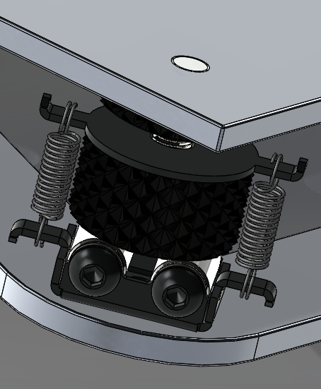
Meanwhile i redesigned the Z-Axis coupling like in the attached picture (work in progress).
I figured i dont need a 2020 profile there and clamp the carrier directly in between the screw nut and coupler. Which then is connected to the rail slider.
Ideally the screw nut should be under the carrier, but thats a trade off for more build space.
The carrier is designed symmetrical so that the center of mass is right where it should be, although it means more weight in general. But of course there is no practical way i can think of to distribute the weight evenly from the 3-point bearing to the carrier. The one side with two bearings will have more weight to carry. I believe that is what you meant with tilting.
Anyhow with the 3-Point setup you are able to compensate that even if the carrier is bent link a banana. Most likely the axis itself will be heavier than the prints.
Synchronize 3 motors is a nightmare i guess.
The problem with other kinematic couplings is that they do not have a moving surface (= ball bearing), either only a ball shape or like in your example a magnet. That will unavoidably result in jerk (stick/slip effect). This might be overrated but you might as well do it right.
|
Re: Thoughts on my design please July 14, 2020 07:55AM |
Registered: 11 years ago Posts: 5,780 |
If you use a controller like the Duet you can drive 3 screws independently and autolevel the bed, but there should be no need for that if the machine is solidly built. You can easily keep 3 screws in sync with a looped belt, and to me, that's a lot easier, cheaper, and more reliable than autoleveling.
The idea behind the kinematic mount is to allow the bed to expand without creating lateral forces that would cause anything, such as the bed support, to flex. Other than sitting on magnets in oversized holes, I'm not sure how the design in the video works- it looks like the bed just sits on magnets and is free to expand, but without any guidance, so for example, if power is lost mid print, you won't necessarily be able to resume printing because the bed may not expand to the same position is was in before power was lost. Mid print power loss is a pretty rare event so it probably doesn't matter. If the machine shakes it may allow the bed to slide a little during prints, and that could be a problem for print quality.
I wouldn't worry about the center of mass of the bed and its support structure. It's not going to be flung back and forth at high speed. In my printer I used a T shaped bed support so that the leveling screws would be located close to the bearing blocks. With the screws at the center of the bed, adjusting the roll screw lifts one side and lowers the other an equal amount which makes leveling the bed just a hair trickier than if the screws were all located on opposite sides of the bed. Using two lifters at the center of the bed creates a double cantilever, but it's a very short cantilever. Using a third belt or screw to do the lifting eliminates any worries about the support flexing or play in the Z axis bearing blocks, or vibration causing the edges of the bed to bounce.
Ultra MegaMax Dominator 3D printer: [drmrehorst.blogspot.com]
|
Re: Thoughts on my design please July 14, 2020 08:22AM |
Registered: 3 years ago Posts: 15 |
Thanks for your feedback.
I was thinking of connecting the two motors with a belt. But then again i want to run two sets of independent end stops, that should fix any misalignment during homing i hope.
Probably i will go with the older SKR boards that support that natively or they come up with a 1.5 and fix that flaw.
Auto-leveling is not a bad thing in my opinion, it should be in the homing procedure or at least a regular routine. I want to add an piezo on top of the hotend for that purpose. Probably overkill again, but coming from an occupation in precision machines...
I suppose the magnets are strong enough to deal with a little shake. For 3D printing probably precise enough. But why? I mean why arent kinematic mounts a thing?
I believe MGN12 and 1404 ball screws are still more than sufficient for the Z-axis and probably laugh over the stress you put on them. Yes it doesnt accelerate much, but still i kind of worry that the uneven load is not ideal in the long run.
|
Re: Thoughts on my design please July 14, 2020 10:51AM |
Registered: 6 years ago Posts: 1,007 |
Quote
the_digital_dentist
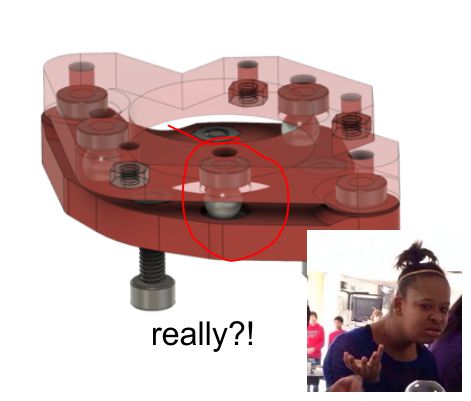
.... Other than sitting on magnets in oversized holes, I'm not sure how the design in the video works- it looks like the bed just sits on magnets and is free to expand, but without any guidance, so for example, if power is lost mid print, you won't necessarily be able to resume printing because the bed may not expand to the same position is was in before power was lost......
From what I see, I think that on the bed underside, there must be three short cylinders most probably magnets , on the carrier the lower left cylindrical hole should be a tight fit, the lower left, elongated to allow X expansion while blocking rotation in Z, the third bigger round hole allow X, Y expansion in both directions, all three having underneath magnets to hold the bed down.
Looks OK but not very good as these red parts are 3D printed. Beside, is the top or the hole bottom the Z reference ? As for the holding force, I wonder how strong with this set up. Can't be great as obviously no proper magnetic path with these plastic parts.
Anyway, "Wait and not see" !
"A comical prototype doesn't mean a dumb idea is possible" (Thunderf00t)
|
Re: Thoughts on my design please July 14, 2020 12:06PM |
Registered: 11 years ago Posts: 5,780 |
Kinematic mounts aren't a "thing" and 4-screw bed leveling is a "thing" for the same reason: ignorance.
For two motors you don't need two endstop switches or a sensor for autoleveling. Simply set the physical endstops to force the bed pitch to be square with Z when both ends of the bed hit the physical stops. Then bring the bed back up to the Z=0 position that can be defined by a single switch. This is the technique that the Prusa printer's use to square the X axis with the Z axis. In simplest operation, the controller sends the bed beyond the end of the Z axis, and reduce the motor current a bit while so it doesn't mangle anything or make too much noise. Then put the current back to normal and home Z. Or if you'd rather not have to do any of that, simply connect the two screws with a belt to a single motor. It will never tilt so you won't have to keep fixing it automatically or manually, but your youtube videos will not be very popular.
Ultra MegaMax Dominator 3D printer: [drmrehorst.blogspot.com]
|
Re: Thoughts on my design please July 15, 2020 03:38AM |
Registered: 6 years ago Posts: 1,007 |
POPULAR you said ? Like this "design" with 3 independent lead screws and many linear rails to tram the bed !
[www.thingiverse.com]
"A comical prototype doesn't mean a dumb idea is possible" (Thunderf00t)
[www.thingiverse.com]
"A comical prototype doesn't mean a dumb idea is possible" (Thunderf00t)
|
Re: Thoughts on my design please July 15, 2020 06:24AM |
Registered: 3 years ago Posts: 15 |
|
Re: Thoughts on my design please July 15, 2020 07:53AM |
Registered: 11 years ago Posts: 5,780 |
Nothing exceeds like excess!
I've seen a youtube video of that one, of course. Complication for complication's sake. Or should I say complication for click's sake?
Ultra MegaMax Dominator 3D printer: [drmrehorst.blogspot.com]
I've seen a youtube video of that one, of course. Complication for complication's sake. Or should I say complication for click's sake?
Ultra MegaMax Dominator 3D printer: [drmrehorst.blogspot.com]
|
Re: Thoughts on my design please July 15, 2020 08:51AM |
Registered: 3 years ago Posts: 15 |
|
Re: Thoughts on my design please July 20, 2020 09:48AM |
Registered: 3 years ago Posts: 15 |
Speaking of endstops... Why is it that the manufacturers tend to start using only one per axis?
Sure you can set you max. position, but wouldn't it be the right thing to do and use max/min endstops? Or you could do it sensorless, which seems to be a pain on CoreXY's.
Not sure i can find a board supporting my idea.
Sure you can set you max. position, but wouldn't it be the right thing to do and use max/min endstops? Or you could do it sensorless, which seems to be a pain on CoreXY's.
Not sure i can find a board supporting my idea.
|
Re: Thoughts on my design please July 20, 2020 10:25AM |
Registered: 6 years ago Posts: 1,007 |
Quote
NEONBLACK
Speaking of endstops... Why is it that the manufacturers tend to start using only one per axis?
Sure you can set you max. position, but wouldn't it be the right thing to do and use max/min endstops? Or you could do it sensorless, which seems to be a pain on CoreXY's.
Not sure i can find a board supporting my idea.
I never understood why there was a Max and Min input on the control boards, a waste of inputs as one per axis is enough to set the Min (origin). Even the Max can use this input, as the system knows in which direction it is going.
Min Max endstops are only be required for security reason to cut directly the motor power supply for more serious machines than these small 3D printers.
So mfgs are doing the right thing.
"A comical prototype doesn't mean a dumb idea is possible" (Thunderf00t)
|
Re: Thoughts on my design please July 21, 2020 05:58AM |
Registered: 12 years ago Posts: 1,450 |
The first CNC miller that I made had all 6 limit switches wired in series (they were connected as NC switches) The controller "knew" which motor it was running and in which direction. Any operation of any of the 6 limit switches except when it was homing that axis would signal an error - machining beyond the limits, broken wire or possibly a screwdriver dropped in the works. The control program for 3D printers normally have software limits so that it won't even try to print beyond the edge of the printable area. The Mach3 program on my miller would try to cut all the way to Birmingham if the G code was fouled up so the limits were useful.
As far as having the extra limit switches on the board I find them useful as special inputs for such things as Z probe detect, emergency stop button etc..
Mike
As far as having the extra limit switches on the board I find them useful as special inputs for such things as Z probe detect, emergency stop button etc..
Mike
|
Re: Thoughts on my design please July 21, 2020 07:43AM |
Registered: 3 years ago Posts: 15 |
On real CNC machines you have all end stop switches, software limits in the PLC plus the NC and an additional threshold to those and torque monitoring limiting and what not. Not to mention positioning encoder, closed loops, etc.
Here it's like there is missing a certain factor of safety. Granted crashing isn't the main consideration here. Kind of awesome that positioning works this good at all.
Leaves me bewildered what to do.
Here it's like there is missing a certain factor of safety. Granted crashing isn't the main consideration here. Kind of awesome that positioning works this good at all.
Leaves me bewildered what to do.
Sorry, only registered users may post in this forum.