Question regarding CoreXY design (in particular the_digital_dentist's UMMD)
Posted by build3r
|
Question regarding CoreXY design (in particular the_digital_dentist's UMMD) January 03, 2021 12:07PM |
Registered: 5 years ago Posts: 7 |
Recently, I have been studying CoreXY builds. My longer term goal is to build one, and while it is clear to me that this will include some trial and error, I hope to learn as much as possible from others. Right now, I don't have the time to start and thus keep reading and thinking ;-)
Reading through digital dentist's blogspot pages, in particular the ones about the "UMMD" printer, I wondered about a few points
Reading through digital dentist's blogspot pages, in particular the ones about the "UMMD" printer, I wondered about a few points
- Z axis
As far as I see, there are two linear rails for the belt-driven Z axis. Isn't there a problem with their alignment and binding, in particular in combination with thermal expansion? Maybe I missed a design feature? - Extruder carriage length
I first did not understand why the extruder carriage needed to be that long, but then realized that this was because the XY assembly was sitting on top of the frame and had to "reach down" to the print bed, across the T-slot profiles, linear rails, and build plates. Couldn't this be avoided by mounting the XY assembly "upside down", i.e. hanging from the frame rather than sitting on top of it? Or are there reasons not to do this? I imagine that it might be less practical for servicing, but maybe there also are other reasons? - Belt-driven vs. lead screw-driven Z axis
I read that one reason for the belt solution was to avoid ringing from possibly not fully linear long lead screws. On the other hand, the belt solution also is not that simple, with the worm gear providing the transmission ratio that the lead screw would otherwise. How critical is such "ringing", and does it matter in practice, in particular in designs that have a shorter usable Z height?
|
Re: Question regarding CoreXY design (in particular the_digital_dentist's UMMD) January 04, 2021 07:33AM |
Registered: 11 years ago Posts: 5,780 |
Yes, two linear guides for the Z axis. No, no alignment or thermal problems. The linear guides are bolted to t-slot that is bolted to the printer's frame. There is a t-slot cross bar at the bottom and the bed support is also a t-slot that runs across the two Z guides. I was concerned that with the chamber being heated that there could be some problems if the whole frame didn't heat up as a unit, but it works fine.
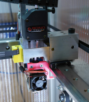
The extruder carriage was very long initially because the XY mechanism is on top of the frame instead of under it, and the bed support was mounted between the two Z axis bearing blocks. I have since remounted the bed support by flipping the support brackets over which lifted the bed by about 60 mm. The current state of the extruder carriage can be seen here:
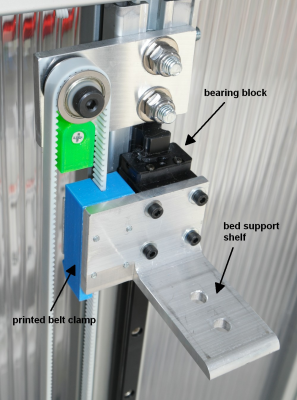
Still a little longer than "normal" but not much. I haven't noticed any change in performance since shortening the carriage. The metal plate that connects the extruder to the hot end is 5mm thick aluminum, so it doesn't flex enough to matter, and the X axis linear guide bearings don't have any play. This post details the updates to the Z axis that allowed the shortening of the extruder carriage: [drmrehorst.blogspot.com]
Lead screws can be made to work fine, as can belts, but it is easier to make a belt driven Z axis that's very long. I decided to use belts because at the time I built UMMD, I didn't see anyone else doing it and I wondered why, and unlike screws, belts cannot cause Z wobble (not ringing which is an XY phenomenon). I settled on the worm gear drive after looking at brakes, clutches, and testing shorted motor windings, because it was the lowest cost solution that would prevent the bed from moving when the Z axis motor power was cut. Shorting the motor didn't work at all. The high reduction ratio of the worm gearbox provides good Z axis resolution and allows a single motor to lift the massive bed assembly plus the weight of the print without having to use an external motor driver. Gear driven Z axis requires very high quality gears, and the gears in the Rino are about as good as you can get (that's an $800 unit if you buy it new).
You could flip the XY stage over and put the extruder carriage closer to the bed plate. That would require making the frame wider so that the tops of the Z axis t-slot don't interfere with the XY belts. I built it the way I did because I wanted to keep the XY stuff visible for easy servicing, but it rarely needs servicing. The extruder carriage does, especially when changing extruders or heater blocks, but that would be equally accessible no matter how you build the XY stage. As I have built it, the extruder and hotend can be removed without releasing the belts from the carriage, so you don't have to retension the belts after making changes to the extruder. I also built it so the Z axis and the XY stage could be removed from the printer as a units, rather than taken into pieces. I've never had to do either, so the design could easily be changed to something that allows for a smaller extruder carriage. I initially had some ideas about making a corexy stage that could be dropped onto different frames with different length Z axes so the XY stage was built first as a module.
Check some of the other posts regarding updates to the design (there have been many). I have gone to optical endstops for all three axes, put the printer's origin at the center of the bed, and rebuilt the X axis using slightly smaller, simpler aluminum tubes to hold the pulleys. The whole XY stage can be made from one size of aluminum tubing, so you buy one piece of tubing, cut it up and drill it and you have all the pulley, motor, and extruder belt clamp mounts. I am still using a screw to adjust the Z=0 position but it isn't really needed. You can put the Z=0 sensor anywhere along the Z axis and then program an offset to put the nozzle at the bed height.
The only change I'd like to make now is to make it easier to swap hot-ends between one with a large nozzle and a volcano heater block and a small nozzle and regular heater block. The most difficult part of doing that would be to come up with a connector for the electrical connections.
Edited 6 time(s). Last edit at 01/04/2021 02:11PM by the_digital_dentist.
Ultra MegaMax Dominator 3D printer: [drmrehorst.blogspot.com]
|
Re: Question regarding CoreXY design (in particular the_digital_dentist's UMMD) January 05, 2021 05:30AM |
Registered: 5 years ago Posts: 7 |
Thanks for your detailed answer, that clarifies a lot.
Good to hear that this works! I'd have imagined that along the Z axis the alignment would be more problematic than for the XY stage because of the overall lenght and because the T-slot bars likely are not fully flat.
Do you think that there is a little bit of flex in either the vertical bars or somewhere else that makes this possible?
How did you adjust the Z rails so that they became parallel and perpendicular to the XY plane? With so many "degrees of freedom" this does not sound trivial to me. Starting with one fixed and then moving the Z carriage up and down and then fastening everything?
Quote
the_digital_dentist
Yes, two linear guides for the Z axis. No, no alignment or thermal problems. The linear guides are bolted to t-slot that is bolted to the printer's frame. There is a t-slot cross bar at the bottom and the bed support is also a t-slot that runs across the two Z guides. I was concerned that with the chamber being heated that there could be some problems if the whole frame didn't heat up as a unit, but it works fine.
Good to hear that this works! I'd have imagined that along the Z axis the alignment would be more problematic than for the XY stage because of the overall lenght and because the T-slot bars likely are not fully flat.
Do you think that there is a little bit of flex in either the vertical bars or somewhere else that makes this possible?
How did you adjust the Z rails so that they became parallel and perpendicular to the XY plane? With so many "degrees of freedom" this does not sound trivial to me. Starting with one fixed and then moving the Z carriage up and down and then fastening everything?
|
Re: Question regarding CoreXY design (in particular the_digital_dentist's UMMD) January 05, 2021 02:28PM |
Registered: 11 years ago Posts: 5,780 |
Some t-slot has a sort of flat surface and some doesn't. The stuff I used didn't, so I milled flat surfaces into the vertical t-slot members that the Z axis guides rails mounted on. You can see the shallow "slot" I milled at the very top of this picture:
IRIC, the "slot" was 0.25 mm deep.
The frame of the printer is built square by milling the ends of the t-slot and matching lengths of the frame members. The members are then bolted directly to each other and squareness verified with diagonal measurements. The guide rails are mounted on the t-slot with a single metal spacer to keep them parallel to the t-slot, then the Z axis sub frame is assembled, and finally the Z axis sub frame is mounted in the main frame using a single metal spacer to ensure that the Z frame is parallel to the back of the printer's frame.
Since the frame is square and the Z axis rails are parallel to the frame, Z is perpendicular to the XY plane. All axes were verified with measurements and prints.
It seems like many degrees of freedom, but it's very simple compared to designs using 4 guide rails and screws to lift the bed. That's just asking for trouble, especially when you look at how the frames are usually built.
Ultra MegaMax Dominator 3D printer: [drmrehorst.blogspot.com]
|
Re: Question regarding CoreXY design (in particular the_digital_dentist's UMMD) April 24, 2021 11:44PM |
Registered: 8 years ago Posts: 1,671 |
Sorry, only registered users may post in this forum.


