Home
>
Reprappers
>
Topic
HELP! How do I control my hot end temperature?
Posted by AndyHow
|
HELP! How do I control my hot end temperature? April 26, 2012 06:23AM |
Registered: 12 years ago Posts: 6 |
Hi all
I've tried to look for references or guidance to this but it seems so hard to find any similar cases.
I've been struggling with my newly built Prusa. Seems like the Pronterface "Set Temp" doesn't really control temperature. How do I really do it? Is it via the firmware?
I just melted my J Head Mk-IIIB with 345c because of it.
I'm using a wades extruder with a EPCOS thermistor/JHead MkIII-B. Double-checked wires. All wrapped in kapton to avoid short. All seems to be in order.
Is there something I didn't do correctly in firmware?
Any help or tips would be great. Thanks
|
Re: HELP! How do I control my hot end temperature? April 26, 2012 07:14AM |
Registered: 14 years ago Posts: 3,742 |
All Pronterface does with "Set Temp" is to send the appropriate GCODE command to the firmware for the temperature.
It is the firmware that maintains the temperature.
Is your thermistor connected and working?
Did you perhaps start a gcode print where the gcode contained much higher temperature commands?
Bob Morrison
Wörth am Rhein, Germany
"Luke, use the source!"
BLOG - PHOTOS - Thingiverse
It is the firmware that maintains the temperature.
Is your thermistor connected and working?
Did you perhaps start a gcode print where the gcode contained much higher temperature commands?
Bob Morrison
Wörth am Rhein, Germany
"Luke, use the source!"
BLOG - PHOTOS - Thingiverse
|
Re: HELP! How do I control my hot end temperature? April 28, 2012 07:37PM |
Registered: 12 years ago Posts: 142 |
|
Re: HELP! How do I control my hot end temperature? April 28, 2012 08:57PM |
Registered: 13 years ago Posts: 643 |
|
Re: HELP! How do I control my hot end temperature? April 28, 2012 11:26PM |
Registered: 12 years ago Posts: 142 |
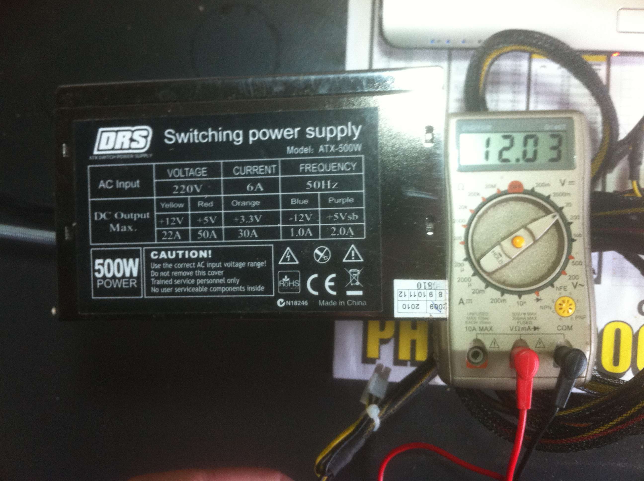
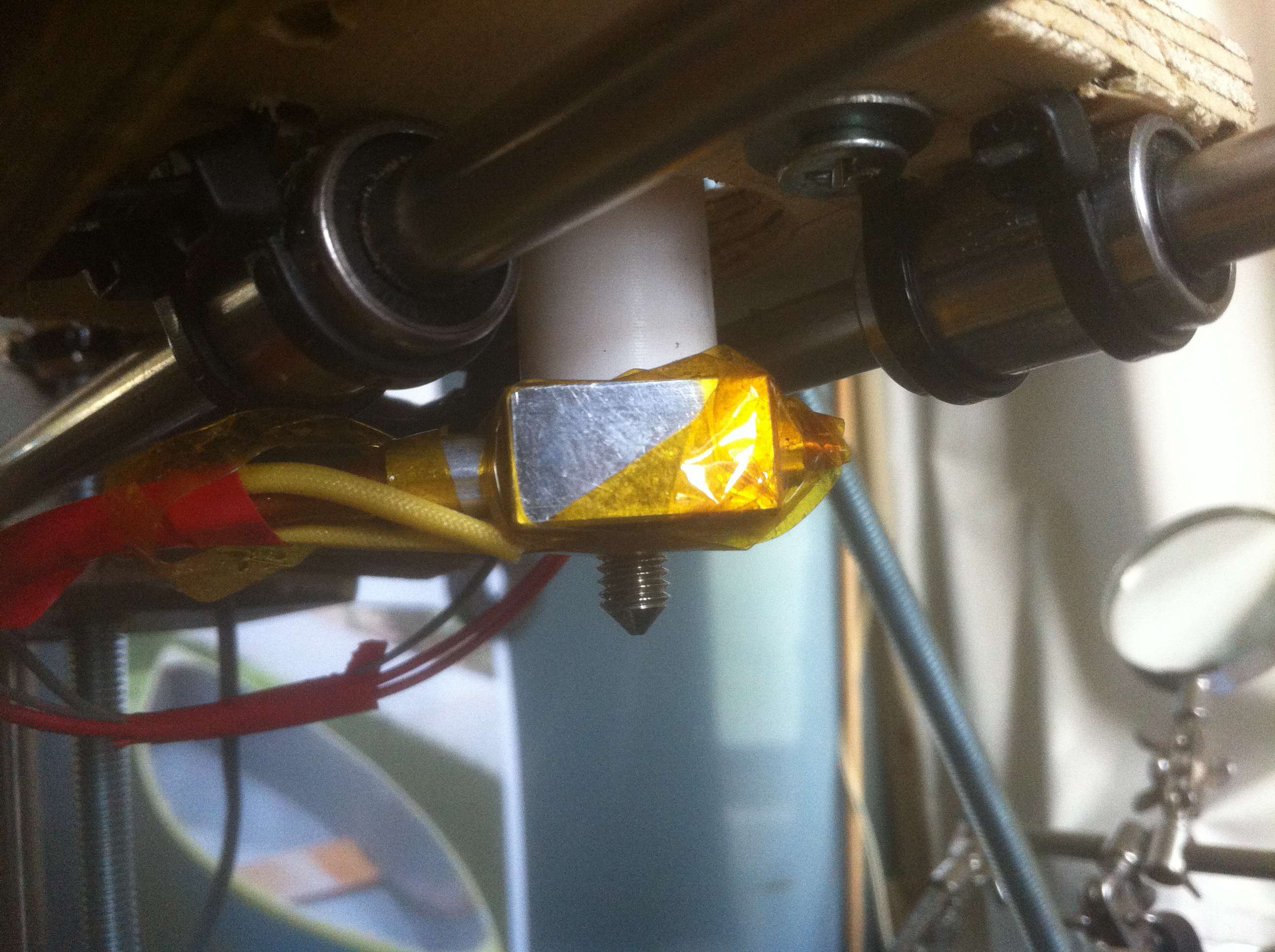
Hot end is the type in the pic and the power supply with multimeter reading of atx power supply is in the other pic.
My hot end reads 17 deg when cold so I assume that is air temp then as follows.
150 at 6mins 42 secs
155 at 7.40
160 at 9.13
165 at 12.40
and
168 at 31 mins 40 secs and steady.
My hotend came with the resistor wrapped and sealed in an alluminum sleeve so i don't know the rating but it was still a loose fit in the alloy square block with that wrapping and alloy sleeve so It may be pretty small.
Multimeter reading of resistor at the connecting wires of my circuit board reads 45.8 ohms on the 200 ohms scale of my Digitor Q1469 meter.
I bought the hotend off ebay Item number: 251036747705 and the sale states the heater is 40 watts so may not be resistor.
rhmorrison, you mention a firmware adjustment. My sanguinololu came with sprinter and bootloader installed and tested. How do I check what the settings are currently. I don't really want to change anything unless necessary as everything else is working perfectly. The axis move at exactly the right measurement.
|
Re: HELP! How do I control my hot end temperature? April 29, 2012 04:07AM |
Registered: 14 years ago Posts: 3,742 |
Quote
gregted
Multimeter reading of resistor at the connecting wires of my circuit board reads 45.8 ohms on the 200 ohms scale of my Digitor Q1469 meter.
Your heating power resistor should be between 6 and 8 ohms.
With 45.8 ohms you will never get it hot enough!
Replace the power resistor and make sure it has a tight fit.
Bob Morrison
Wörth am Rhein, Germany
"Luke, use the source!"
BLOG - PHOTOS - Thingiverse
|
Re: HELP! How do I control my hot end temperature? April 29, 2012 04:26AM |
Registered: 12 years ago Posts: 142 |
Thanks Bob,
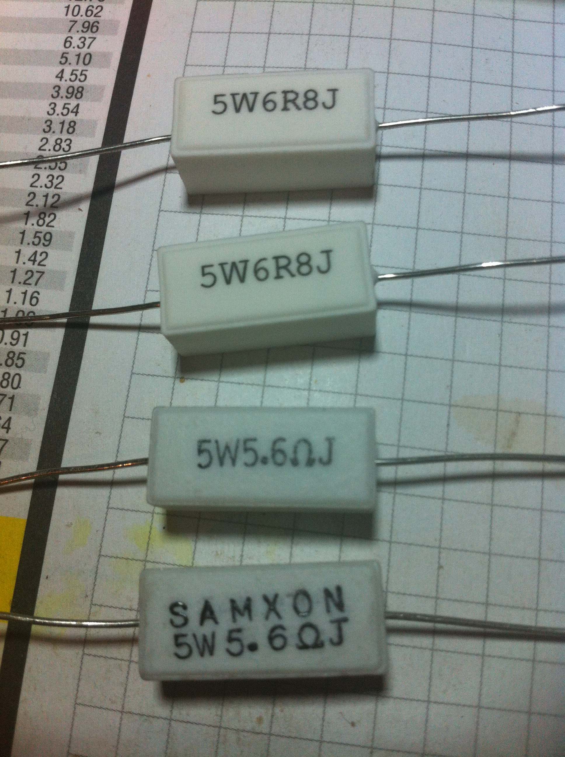
I thought that might be the problem. I have some square wire wound resistors but they are ceramic casings. Pic attached...
Will these work and how do I attach them. The hole in my hot end is circular not square so do I just glue it to the side of the aloy block?
I thought that might be the problem. I have some square wire wound resistors but they are ceramic casings. Pic attached...
Will these work and how do I attach them. The hole in my hot end is circular not square so do I just glue it to the side of the aloy block?
|
Re: HELP! How do I control my hot end temperature? April 29, 2012 08:15PM |
Registered: 12 years ago Posts: 6 |
Thanks Bob.
I changed my thermistor, wrapped the wires with kapton to the edge of the glass and it's still the same.
Would you be able to send me a sample of your working firmware as a guide?
I'd like to get to the bottom of this problem. Thanks in advance.
Here's what I have (Marlin):
#ifndef __CONFIGURATION_H
#define __CONFIGURATION_H
// This determines the communication speed of the printer
#define BAUDRATE 250000
//#define BAUDRATE 115200
//#define BAUDRATE 230400
#define EXTRUDERS 1
// Frequency limit
// See nophead's blog for more info
// Not working O
//#define XY_FREQUENCY_LIMIT 15
// Minimum planner junction speed. Sets the default minimum speed the planner plans for at the end
// of the buffer and all stops. This should not be much greater than zero and should only be changed
// if unwanted behavior is observed on a user's machine when running at very slow speeds.
#define MINIMUM_PLANNER_SPEED 2.0 // (mm/sec)
// If defined the movements slow down when the look ahead buffer is only half full
#define SLOWDOWN
// BASIC SETTINGS: select your board type, thermistor type, axis scaling, and endstop configuration
//// The following define selects which electronics board you have. Please choose the one that matches your setup
// MEGA/RAMPS up to 1.2 = 3,
// RAMPS 1.3 = 33
// Gen6 = 5,
// Sanguinololu 1.2 and above = 62
// Ultimaker = 7,
// Teensylu = 8
#define MOTHERBOARD 33
//===========================================================================
//=============================Thermal Settings ============================
//===========================================================================
//// Thermistor settings:
// 1 is 100k thermistor
// 2 is 200k thermistor
// 3 is mendel-parts thermistor
// 4 is 10k thermistor
// 5 is ParCan supplied 104GT-2 100K
// 6 is EPCOS 100k
// 7 is 100k Honeywell thermistor 135-104LAG-J01
#define THERMISTORHEATER_0 1
//#define THERMISTORHEATER_1 1
#define THERMISTORBED 1
#define HEATER_0_USES_THERMISTOR
//#define HEATER_1_USES_THERMISTOR
//#define HEATER_0_USES_AD595
//#define HEATER_1_USES_AD595
// Select one of these only to define how the bed temp is read.
#define BED_USES_THERMISTOR
//#define BED_USES_AD595
#define BED_CHECK_INTERVAL 5000 //ms
//// Experimental watchdog and minimal temp
// The watchdog waits for the watchperiod in milliseconds whenever an M104 or M109 increases the target temperature
// If the temperature has not increased at the end of that period, the target temperature is set to zero. It can be reset with another M104/M109
/// CURRENTLY NOT IMPLEMENTED AND UNUSEABLE
//#define WATCHPERIOD 5000 //5 seconds
// Actual temperature must be close to target for this long before M109 returns success
//#define TEMP_RESIDENCY_TIME 20 // (seconds)
//#define TEMP_HYSTERESIS 5 // (C¡ã) range of +/- temperatures considered "close" to the target one
//// The minimal temperature defines the temperature below which the heater will not be enabled
#define HEATER_0_MINTEMP 5
//#define HEATER_1_MINTEMP 5
//#define BED_MINTEMP 5
// When temperature exceeds max temp, your heater will be switched off.
// This feature exists to protect your hotend from overheating accidentally, but *NOT* from thermistor short/failure!
// You should use MINTEMP for thermistor short/failure protection.
#define HEATER_0_MAXTEMP 240
//#define HEATER_1_MAXTEMP 275
//#define BED_MAXTEMP 150
// Wait for Cooldown
// This defines if the M109 call should not block if it is cooling down.
// example: From a current temp of 220, you set M109 S200.
// if CooldownNoWait is defined M109 will not wait for the cooldown to finish
#define CooldownNoWait true
// Heating is finished if a temperature close to this degree shift is reached
#define HEATING_EARLY_FINISH_DEG_OFFSET 1 //Degree
// PID settings:
// Uncomment the following line to enable PID support.
#define PIDTEMP
#ifdef PIDTEMP
#if MOTHERBOARD == 62
#error Sanguinololu does not support PID, sorry. Please disable it.
#endif
//#define PID_DEBUG // Sends debug data to the serial port.
//#define PID_OPENLOOP 1 // Puts PID in open loop. M104 sets the output power in %
#define PID_MAX 255 // limits current to nozzle; 255=full current
#define PID_INTEGRAL_DRIVE_MAX 255 //limit for the integral term
#define K1 0.95 //smoothing factor withing the PID
#define PID_dT 0.1 //sampling period of the PID
//To develop some PID settings for your machine, you can initiall follow
// the Ziegler-Nichols method.
// set Ki and Kd to zero.
// heat with a defined Kp and see if the temperature stabilizes
// ideally you do this graphically with repg.
// the PID_CRITIAL_GAIN should be the Kp at which temperature oscillatins are not dampned out/decreas in amplitutde
// PID_SWING_AT_CRITIAL is the time for a full period of the oscillations at the critical Gain
// usually further manual tunine is necessary.
#define PID_CRITIAL_GAIN 50
#define PID_SWING_AT_CRITIAL 47 //seconds
//#define PID_PI //no differentail term
#define PID_PID //normal PID
#ifdef PID_PID
//PID according to Ziegler-Nichols method
// #define DEFAULT_Kp (0.6*PID_CRITIAL_GAIN)
// #define DEFAULT_Ki (2*Kp/PID_SWING_AT_CRITIAL*PID_dT)
// #define DEFAULT_Kd (PID_SWING_AT_CRITIAL/8./PID_dT)
// Ultitmaker
#define DEFAULT_Kp 22.2
#define DEFAULT_Ki (1.25*PID_dT)
#define DEFAULT_Kd (99/PID_dT)
// Mendel Parts V9 on 12V
// #define DEFAULT_Kp 63.0
// #define DEFAULT_Ki (2.25*PID_dT)
// #define DEFAULT_Kd (440/PID_dT)
#endif
#ifdef PID_PI
//PI according to Ziegler-Nichols method
#define DEFAULT_Kp (PID_CRITIAL_GAIN/2.2)
#define DEFAULT_Ki (1.2*Kp/PID_SWING_AT_CRITIAL*PID_dT)
#define DEFAULT_Kd (0)
#endif
// this adds an experimental additional term to the heatingpower, proportional to the extrusion speed.
// if Kc is choosen well, the additional required power due to increased melting should be compensated.
#define PID_ADD_EXTRUSION_RATE
#ifdef PID_ADD_EXTRUSION_RATE
#define DEFAULT_Kc (3) //heatingpower=Kc*(e_speed)
#endif
#endif // PIDTEMP
//===========================================================================
//=============================Mechanical Settings===========================
//===========================================================================
// Endstop Settings
#define ENDSTOPPULLUPS // Comment this out (using // at the start of the line) to disable the endstop pullup resistors
// The pullups are needed if you directly connect a mechanical endswitch between the signal and ground pins.
const bool X_ENDSTOPS_INVERTING = false; // set to true to invert the logic of the endstops.
const bool Y_ENDSTOPS_INVERTING = false; // set to true to invert the logic of the endstops.
const bool Z_ENDSTOPS_INVERTING = false; // set to true to invert the logic of the endstops.
// For optos H21LOB set to true, for Mendel-Parts newer optos TCST2103 set to false
// For Inverting Stepper Enable Pins (Active Low) use 0, Non Inverting (Active High) use 1
#define X_ENABLE_ON 0
#define Y_ENABLE_ON 0
#define Z_ENABLE_ON 0
#define E_ENABLE_ON 0
// Disables axis when it's not being used.
#define DISABLE_X false
#define DISABLE_Y false
#define DISABLE_Z false
#define DISABLE_E false
// Inverting axis direction
//#define INVERT_X_DIR false // for Mendel set to false, for Orca set to true
//#define INVERT_Y_DIR true // for Mendel set to true, for Orca set to false
//#define INVERT_Z_DIR false // for Mendel set to false, for Orca set to true
//#define INVERT_E_DIR true // for direct drive extruder v9 set to true, for geared extruder set to false
#define INVERT_X_DIR false // for Mendel set to false, for Orca set to true
#define INVERT_Y_DIR false // for Mendel set to true, for Orca set to false
#define INVERT_Z_DIR true // for Mendel set to false, for Orca set to true
#define INVERT_E_DIR true // for direct drive extruder v9 set to true, for geared extruder set to false
//// ENDSTOP SETTINGS:
// Sets direction of endstops when homing; 1=MAX, -1=MIN
#define X_HOME_DIR -1
#define Y_HOME_DIR -1
#define Z_HOME_DIR -1
#define min_software_endstops false //If true, axis won't move to coordinates less than zero.
#define max_software_endstops true //If true, axis won't move to coordinates greater than the defined lengths below.
#define X_MAX_LENGTH 180
#define Y_MAX_LENGTH 191
#define Z_MAX_LENGTH 140
//// MOVEMENT SETTINGS
#define NUM_AXIS 4 // The axis order in all axis related arrays is X, Y, Z, E
//#define HOMING_FEEDRATE {50*60, 50*60, 4*60, 0} // set the homing speeds (mm/min)
#define HOMING_FEEDRATE {1500, 1500, 300, 0} // set the homing speeds (mm/min)
//homing hits the endstop, then retracts by this distance, before it tries to slowly bump again:
#define X_HOME_RETRACT_MM 5
#define Y_HOME_RETRACT_MM 5
#define Z_HOME_RETRACT_MM 1
#define AXIS_RELATIVE_MODES {false, false, false, false}
#define MAX_STEP_FREQUENCY 40000 // Max step frequency for Ultimaker (5000 pps / half step)
// default settings
//// Calibration variables
// X, Y, Z, E steps per unit - Metric Prusa Mendel with Hinged Greg's Wade extruder:
// SloateBot:
// X and Y axes are 19.25 mm pitch diameter, SDP-SI.com #A6M35M012DF1005, which gives us
// C=19.25pi mm per rev. At 1/2 stepping that is 400 steps per rev. so then we have 400/(19.25pi) = 6.614231401221625 stepspermm
// At 1/4 stepping that is 800 steps per rev. so then we have 800/(19.25pi) = 13.22846280244325 stepspermm
// At 1/16th stepping that is 3200/(19.25pi) = 52.913851209772999 stepspermm.
// Z-axis: 1.8 degree is 200 steps per revolution, 1 revolution is 1.25 mm (z-rod pitch), at 1/16th stepping
// we have 3200 steps/1.25 mm to give 2560 stepspermm
// E-axis: 7.25 mm is diameter of hobbed bolt, so C = 7.25pi per rev. At 1/16th stepping this is: 800/(7.25pi), but we have
// hinged wade extruder, so this is converted 43/10 ratio. I think these are all wrong anyway... just do 4x the quarter stepping
// we had before
// UGH -- GO BACK TO 1/4 STEPPING FOR EXTRUDER. LOSING STEPS at 1/16th stepping
#define DEFAULT_AXIS_STEPS_PER_UNIT {79.20, 79.20, 2560, 124.530011898862}
// #define DEFAULT_AXIS_STEPS_PER_UNIT {79.20,79.20,200*8/3,760*1.1} // default steps per unit for ultimaker
//#define DEFAULT_AXIS_STEPS_PER_UNIT {40, 40, 3333.92, 67} //sells mendel with v9 extruder
#define DEFAULT_MAX_FEEDRATE {500, 500, 5, 45} // (mm/sec)
#define DEFAULT_MAX_ACCELERATION {900,900,80,10000} // X, Y, Z, E maximum start speed for accelerated moves. E default values are good for skeinforge 40+, for older versions raise them a lot.
// #define DEFAULT_MAX_ACCELERATION {9000,9000,100,10000} // X, Y, Z, E maximum start speed for accelerated moves. E default values are good for skeinforge 40+, for older versions raise them a lot.
#define DEFAULT_ACCELERATION 3000 // X, Y, Z and E max acceleration in mm/s^2 for printing moves
#define DEFAULT_RETRACT_ACCELERATION 3000 // X, Y, Z and E max acceleration in mm/s^2 for r retracts
#define DEFAULT_MINIMUMFEEDRATE 0.0 // minimum feedrate
#define DEFAULT_MINTRAVELFEEDRATE 0.0
// minimum time in microseconds that a movement needs to take if the buffer is emptied. Increase this number if you see blobs while printing high speed & high detail. It will slowdown on the detailed stuff.
#define DEFAULT_MINSEGMENTTIME 20000 // Obsolete delete this
#define DEFAULT_XYJERK 20.0 // (mm/sec)
#define DEFAULT_ZJERK 0.4 // (mm/sec)
#define DEFAULT_EJERK 5.0 // (mm/sec)
//===========================================================================
//=============================Additional Features===========================
//===========================================================================
// EEPROM
// the microcontroller can store settings in the EEPROM, e.g. max velocity...
// M500 - stores paramters in EEPROM
// M501 - reads parameters from EEPROM (if you need reset them after you changed them temporarily).
// M502 - reverts to the default "factory settings". You still need to store them in EEPROM afterwards if you want to.
//define this to enable eeprom support
#define EEPROM_SETTINGS
//to disable EEPROM Serial responses and decrease program space by ~1700 byte: comment this out:
// please keep turned on if you can.
#define EEPROM_CHITCHAT
// The hardware watchdog should halt the Microcontroller, in case the firmware gets stuck somewhere. However:
// the Watchdog is not working well, so please only enable this for testing
// this enables the watchdog interrupt.
//#define USE_WATCHDOG
//#ifdef USE_WATCHDOG
// you cannot reboot on a mega2560 due to a bug in he bootloader. Hence, you have to reset manually, and this is done hereby:
//#define RESET_MANUAL
//#define WATCHDOG_TIMEOUT 4 //seconds
//#endif
// extruder advance constant (s2/mm3)
//
// advance (steps) = STEPS_PER_CUBIC_MM_E * EXTUDER_ADVANCE_K * cubic mm per second ^ 2
//
// hooke's law says: force = k * distance
// bernoulli's priniciple says: v ^ 2 / 2 + g . h + pressure / density = constant
// so: v ^ 2 is proportional to number of steps we advance the extruder
//#define ADVANCE
#ifdef ADVANCE
#define EXTRUDER_ADVANCE_K .3
#define D_FILAMENT 1.7
#define STEPS_MM_E 65
#define EXTRUTION_AREA (0.25 * D_FILAMENT * D_FILAMENT * 3.14159)
#define STEPS_PER_CUBIC_MM_E (axis_steps_per_unit[E_AXIS]/ EXTRUTION_AREA)
#endif // ADVANCE
//LCD and SD support
//#define ULTRA_LCD //general lcd support, also 16x2
//#define SDSUPPORT // Enable SD Card Support in Hardware Console
#define SD_FINISHED_STEPPERRELEASE true //if sd support and the file is finished: disable steppers?
//#define ULTIPANEL
#ifdef ULTIPANEL
//#define NEWPANEL //enable this if you have a click-encoder panel
#define SDSUPPORT
#define ULTRA_LCD
#define LCD_WIDTH 20
#define LCD_HEIGHT 4
#else //no panel but just lcd
#ifdef ULTRA_LCD
#define LCD_WIDTH 16
#define LCD_HEIGHT 2
#endif
#endif
// Preheat Constants
#define PLA_PREHEAT_HOTEND_TEMP 180
#define PLA_PREHEAT_HPB_TEMP 70
#define PLA_PREHEAT_FAN_SPEED 255 // Insert Value between 0 and 255
#define ABS_PREHEAT_HOTEND_TEMP 240
#define ABS_PREHEAT_HPB_TEMP 100
#define ABS_PREHEAT_FAN_SPEED 255 // Insert Value between 0 and 255
// A debugging feature to compare calculated vs performed steps, to see if steps are lost by the software.
//#define DEBUG_STEPS
// Arc interpretation settings:
#define MM_PER_ARC_SEGMENT 1
#define N_ARC_CORRECTION 25
//automatic temperature: The hot end target temperature is calculated by all the buffered lines of gcode.
//The maximum buffered steps/sec of the extruder motor are called "se".
//You enter the autotemp mode by a M109 S T F
// the target temperature is set to mintemp+factor*se[steps/sec] and limited by mintemp and maxtemp
// you exit the value by any M109 without F*
// Also, if the temperature is set to a value <mintemp, it is not changed by autotemp.
// on an ultimaker, some initial testing worked with M109 S215 T260 F0.1 in the start.gcode
//#define AUTOTEMP
#ifdef AUTOTEMP
#define AUTOTEMP_OLDWEIGHT 0.98
#endif
const int dropsegments=5; //everything with less than this number of steps will be ignored as move and joined with the next movement
//===========================================================================
//=============================Buffers ============================
//===========================================================================
// The number of linear motions that can be in the plan at any give time.
// THE BLOCK_BUFFER_SIZE NEEDS TO BE A POWER OF 2, i.g. 8,16,32 because shifts and ors are used to do the ringbuffering.
#if defined SDSUPPORT
#define BLOCK_BUFFER_SIZE 16 // SD,LCD,Buttons take more memory, block buffer needs to be smaller
#else
#define BLOCK_BUFFER_SIZE 16 // maximize block buffer
#endif
//The ASCII buffer for recieving from the serial:
#define MAX_CMD_SIZE 96
#define BUFSIZE 4
#include "thermistortables.h"
#endif //__CONFIGURATION_H
|
Re: HELP! How do I control my hot end temperature? April 30, 2012 03:00AM |
Registered: 12 years ago Posts: 51 |
AndyHow
I think you should try disabling PID in your firmware as this gave me incorrect temperature readings until I had it configured correctly. PID is a PWM algorithm to finely control hot end temperature. Your hot end will work without using PID and this is called "bang bang" but maybe you can implement PID at some point in the future instead, when you decide you need fine grained hot end temperature control.
So try commenting out this line:
#define PIDTEMP
Alternatively if you are set on using PID, then try switching to the "Mendel Parts V9 on 12V" settings rather than ultimaker as I suspect these will match your prusa with a #1 thermistor (they work for me).
gregted
I don't like the look of your square resistors without ceramic casings. You should really use a round resistor in a round hole, to get good thermal conductivity with the heater block! Some people secure them by wrapping them in foil until they fit snuggly in the hole. Others fix the resistor in place with high temperature silicon (like Silicoset 158) or some sort of high temperature glue.
|
Re: HELP! How do I control my hot end temperature? April 30, 2012 05:23AM |
Registered: 12 years ago Posts: 6 |
Sorry, only registered users may post in this forum.