Home
>
Reprappers
>
Topic
Advice needed for a new sensitive Z probing method
Posted by leadinglights
|
Advice needed for a new sensitive Z probing method March 25, 2019 02:38PM |
Registered: 12 years ago Posts: 1,450 |
I am looking for some advice on where to start with interfacing a piezo Z probe conditioner (MCU based) to a RAMPS controller with Repetier firmware. I want to be able to send new parameters to the conditioner using an I2C interface and need some guidance on where to look in the Repetier software so that I don't spend too long following blind leads. If it is mostly a matter of uncommenting a few statements or assigning a couple of pins I should be able to hack it - I am an assembly language kind of guy and just too damm old to learn a new language.
There are two parts to the interfacing: Firstly, the controller (RAMPS with Repetier firmware) should recieve signals for an accurate Z Probe contact with a second signal sent out if the Z probe contacted the table but was out of limits. Secondly, the controller should be able to send parameters to the signal conditioner to change the limits that define a good signal. The communication interface on the conditioner for changing parameters is I2C.
The conditioner works to the extent that it can discriminate between a clean nozzle to bed contact and one where there is dirt or plastic in the way but is very much a work in progress presently. Changes in parameters can only be done by reprogramming and there is a lot of work needed to optimise the response.
Background
This builds on my earliest piezo z probes described on [reprap.org] The sensors that for the latest version can be seen on [reprap.org]
The aim of the conditioning circuit is to give an accurate indication of when the nozzle contacts the build stage and to reject false or bad signals while still preventing the nozzle from damaging the build surface. Hopefully, a functioning probe will reject Z-probe operations (Z-pops) caused by for example plastic on the nozzle, bubbles under Kapton film etc.. A second high level trigger will allow the Z-pop ot be repeated - possibly at a slightly different location.
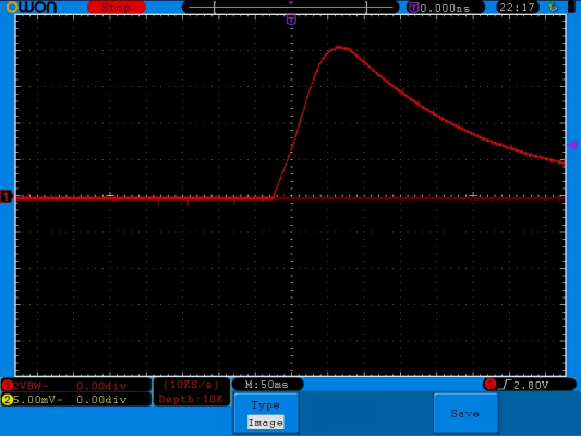
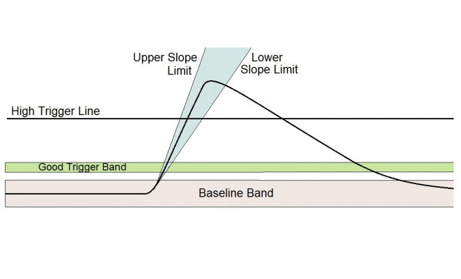
The conditioner consists of a PIC12F1840 with some basic active filtering. The program looks at the morphology (shape) of the signal from the piezos: A signal is passed as good if the baseline was flat and within an upper and lower boundry for a period of time (40 samples) followed by the signal voltage rising at a rate with upper and lower bounds when the voltage falls within a good trigger band. If a good signal is not found a trigger will still be given when a high trigger level is passed. The sort of input obtained from a piezo disk is shown below along with a diagram showing how the shape is divided up into baseline, acceptable trigger region, slope limits and higher level trigger.
Mike
|
Re: Advice needed for a new sensitive Z probing method April 09, 2019 07:56AM |
Registered: 12 years ago Posts: 1,450 |
In the latest tests at a probe approach speed of 2mm/sec a trigger is detected in 20µm ±4µm on a clean glass build stage with a secondary trigger occurs between 80µm and 150µm. The clean trigger ignores contacts with dirty nozzles, the shaking at the end of an XY movement, beginning of a Z movement and even external shocks (hitting the test rig) better than 95% of the time. The secondary trigger works reliably to prevent damage to the build surface in the event of no good trigger being received.
It would be nice to control this from an external controller so that the trigger points could be trimmed for other printers but it looks like it will work well enough for the printer I am presently building so I will leave that to anybody who may be interested.
When I get the chance I will document this and make it available including PIC16 source (warning, assembler code), schematics and Gerber files for the PCB. along with notes on the construction of sensors.
Mike
Edited 1 time(s). Last edit at 04/09/2019 07:58AM by leadinglights.
Sorry, only registered users may post in this forum.

