Home
>
Reprappers
>
Topic
Design nearly done - construction started...
Posted by Maxx Mayhem
|
Design nearly done - construction started... April 12, 2013 09:26PM |
Registered: 11 years ago Posts: 256 |
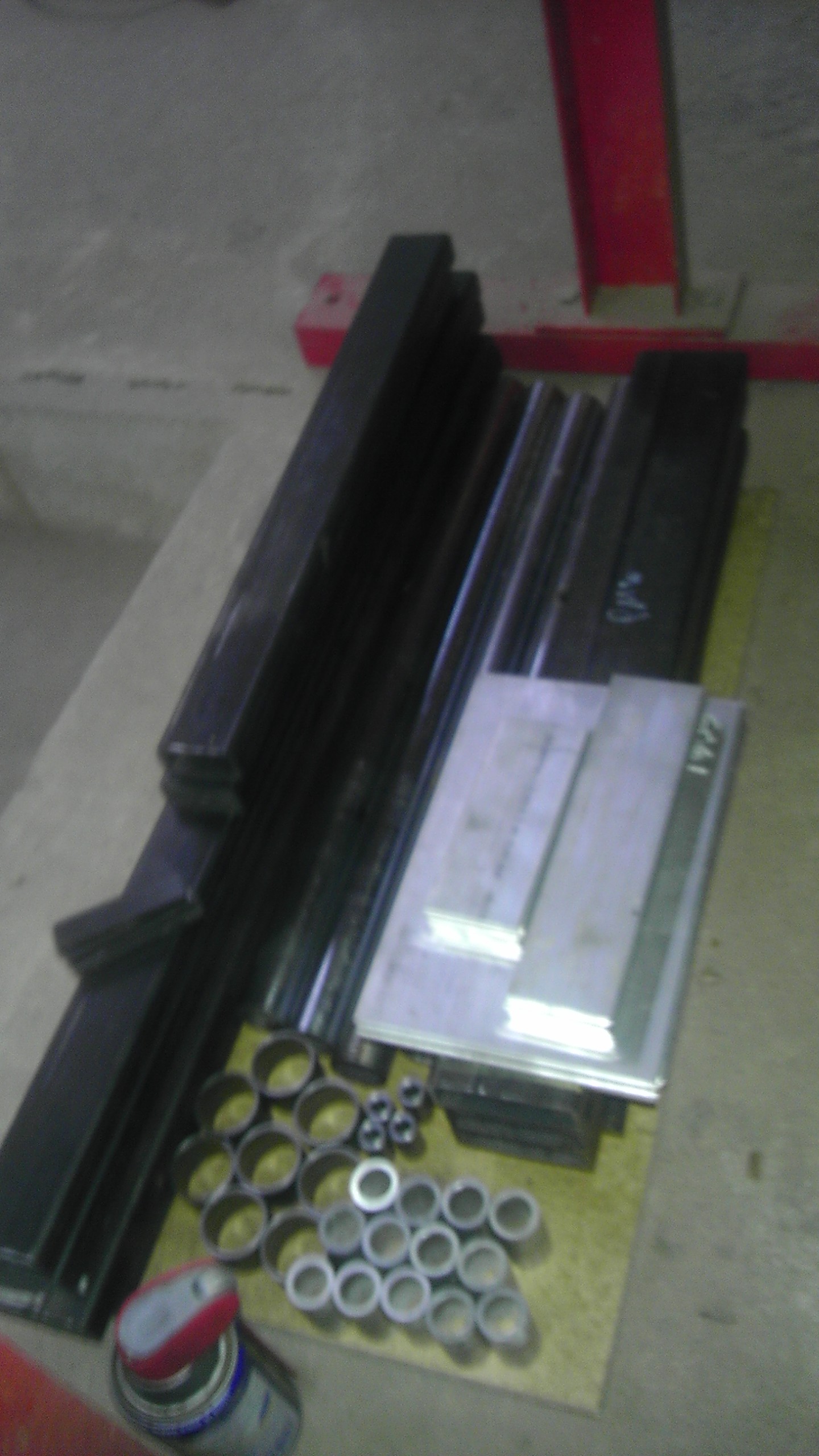
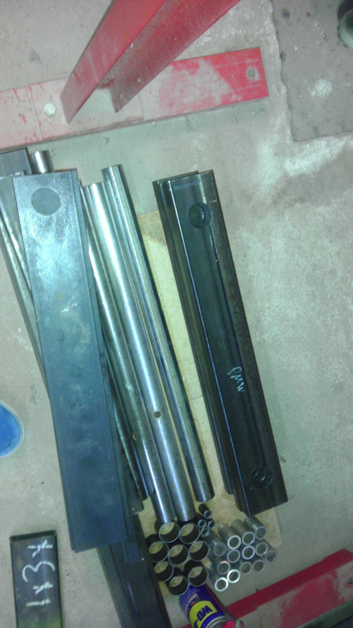
OK so it's one week this evening since I started making parts for my printer... I am doing this the old fashioned way, because for one thing I don't have access to a printer to make parts, and secondly, because I like to make things that are like combinations of other things. Typically this works quite well, as long as I have done my homework. So here's my project. This printer will be a large format; I started wanting 300 x 600 x300 but because I decided to opt for a bowden setup, and my frame is cut out already, it will end up more like 375 x 600 x 300. The frame is being made up of mild steel, mostly 1/8" thick tube, but the Z supports are of 1/4" plate. All this to be welded into one single solid piece. What remains on the frame is to finalize the location of wire runs and nail down the exact location of my rods. The welding will be done to a rather tight specification, with multiple QA checks all the way thru to assure perfect squareness. All components are sanded to fit to a long gauge within a few thousandths. However, there has to be allowance for metal doing what it does, and so I have designed 3 dimensional adjustment collars for my Y and Z rods, as well as my Z screws. These collars (28 pieces) are hand made on a lathe. You can see these in various stages in the picture.
The geometry is as follows... The build plate which will be framed with lightened aluminum is the Z axis. The X axis runs front to back, and the Y axis runs lengthwise. I am building this machine to make (hopefully) large detailed models. I personally like anything Manned space flight but anything that will fit in this envelope. The printer will be fully enclosed, and will have a heater that will maintain just a high room temperature for curing ABS. I have one of those cube heaters that I will control electronnically (as opposed to Bimetal) to attempt to create a proper curing atmosphere for large, detailed ABS models I plan to make.
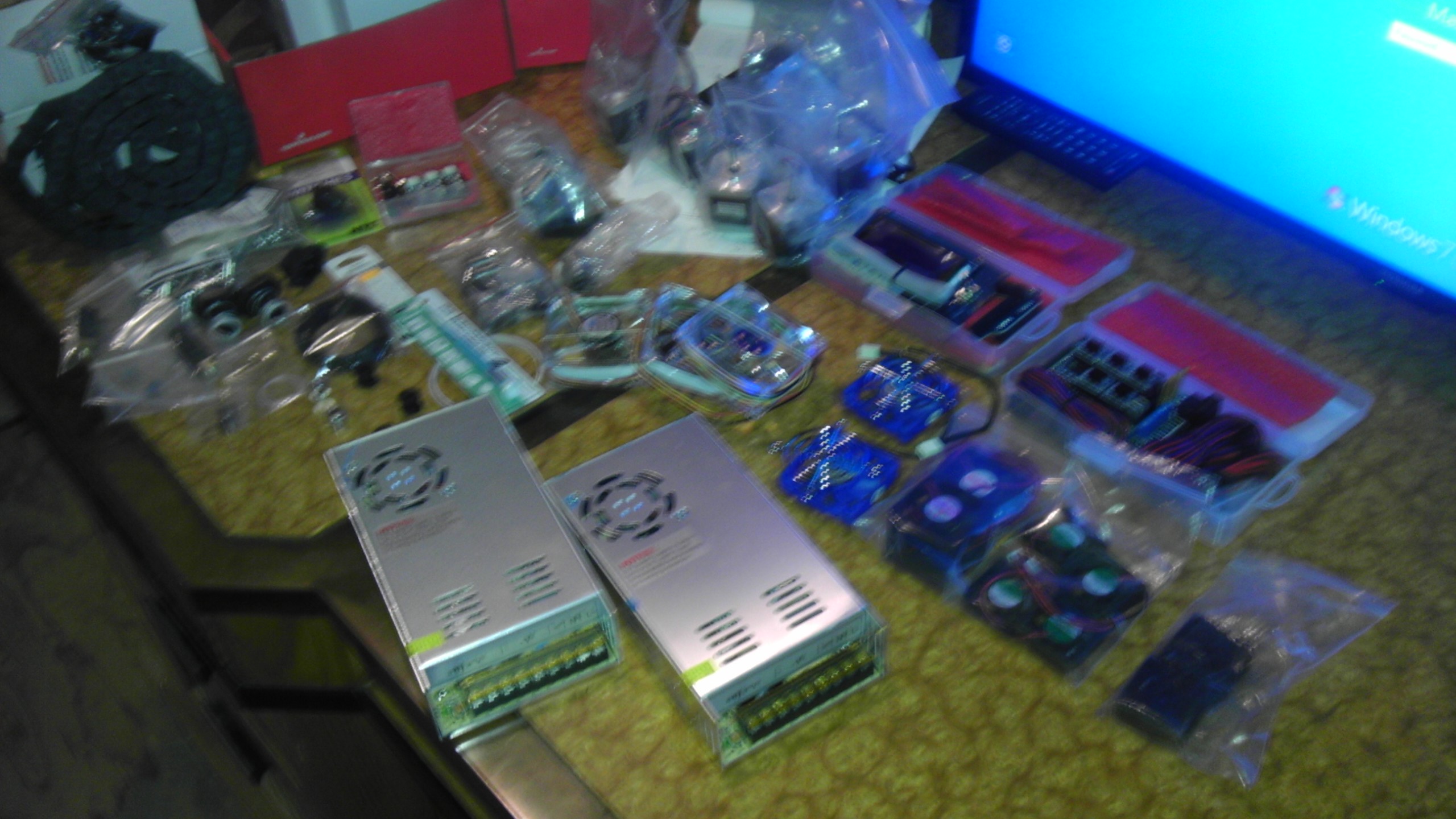
For electronics, I have an Arduino /Ramps 1.4 setup with the LCD controller, I am using #23 motors (200 step) on the Z drive and #17 motors (400 step) on the X, Y and extruders. I am using a direct drive system A pair of bowden tubes (2mm ID) will feed 1.75 mil filiment thru 2 Jhead Mark V-b hotends. At some point I want to add more colors. But I'll hold off on that till I get my test cube to work... There are 2 30 amp PSUs. All electronics draw outside air for cooling. I do not have a definitive count on the number of fans in this thing, there is 1 on each motor, one on the hotends, one on the fresh work, 2 per PSU, and 2 (3?) at the electronics, as well as one or two others for air handling, to keep even temps for curing.
Instead of using drive belts as belts, I will epoxy them to solid channels and use them to make a rack and pinnion drive for the X, Y axis. In this way, I hope to eliminate slop, stretch, and the inherent backlash from the belts.
My theory for this printer is simple; put all the weight and rigidity into the frame and stationary parts, and keep the moving bits as light and uncluttered as possible.
Once I get this thing together, I plan on experimenting with all the various slicers and firmware to see what gives me the results I want.
Sorry if this went long, but I want to share what I am doing with the community. I will continue to update every few days or so, as things progress.
The geometry is as follows... The build plate which will be framed with lightened aluminum is the Z axis. The X axis runs front to back, and the Y axis runs lengthwise. I am building this machine to make (hopefully) large detailed models. I personally like anything Manned space flight but anything that will fit in this envelope. The printer will be fully enclosed, and will have a heater that will maintain just a high room temperature for curing ABS. I have one of those cube heaters that I will control electronnically (as opposed to Bimetal) to attempt to create a proper curing atmosphere for large, detailed ABS models I plan to make.
For electronics, I have an Arduino /Ramps 1.4 setup with the LCD controller, I am using #23 motors (200 step) on the Z drive and #17 motors (400 step) on the X, Y and extruders. I am using a direct drive system A pair of bowden tubes (2mm ID) will feed 1.75 mil filiment thru 2 Jhead Mark V-b hotends. At some point I want to add more colors. But I'll hold off on that till I get my test cube to work...
There are 2 30 amp PSUs. All electronics draw outside air for cooling. I do not have a definitive count on the number of fans in this thing, there is 1 on each motor, one on the hotends, one on the fresh work, 2 per PSU, and 2 (3?) at the electronics, as well as one or two others for air handling, to keep even temps for curing. Instead of using drive belts as belts, I will epoxy them to solid channels and use them to make a rack and pinnion drive for the X, Y axis. In this way, I hope to eliminate slop, stretch, and the inherent backlash from the belts.
My theory for this printer is simple; put all the weight and rigidity into the frame and stationary parts, and keep the moving bits as light and uncluttered as possible.
Once I get this thing together, I plan on experimenting with all the various slicers and firmware to see what gives me the results I want.
Sorry if this went long, but I want to share what I am doing with the community. I will continue to update every few days or so, as things progress.
|
Re: Design nearly done - construction started... April 14, 2013 02:13PM |
Registered: 11 years ago Posts: 381 |
It sounds like a great concept and I'm excited to see more pictures. Please post some updated pics of the structure, as many as you can. I'm currently working on a similar design and I would like to see how you've done yours. Keep up the good work and update as much as you can. Thanks.
--------------| For Everything |--------------------------
Check it out here:
[reprapsquad.wordpress.com].
---------| For Everything Prototype Related |------
Now featuring comp case mods:
[RepRapLab.wordpress.com]
--------------| Find us at Twitter|------------------------
@REPRAPSQUAD (RS Main)
[mobile.twitter.com]
@REPRAPSQUADHQ (ProtoLab)
[mobile.twitter.com]
|
Re: Design nearly done - construction started... April 15, 2013 09:48PM |
Registered: 11 years ago Posts: 256 |
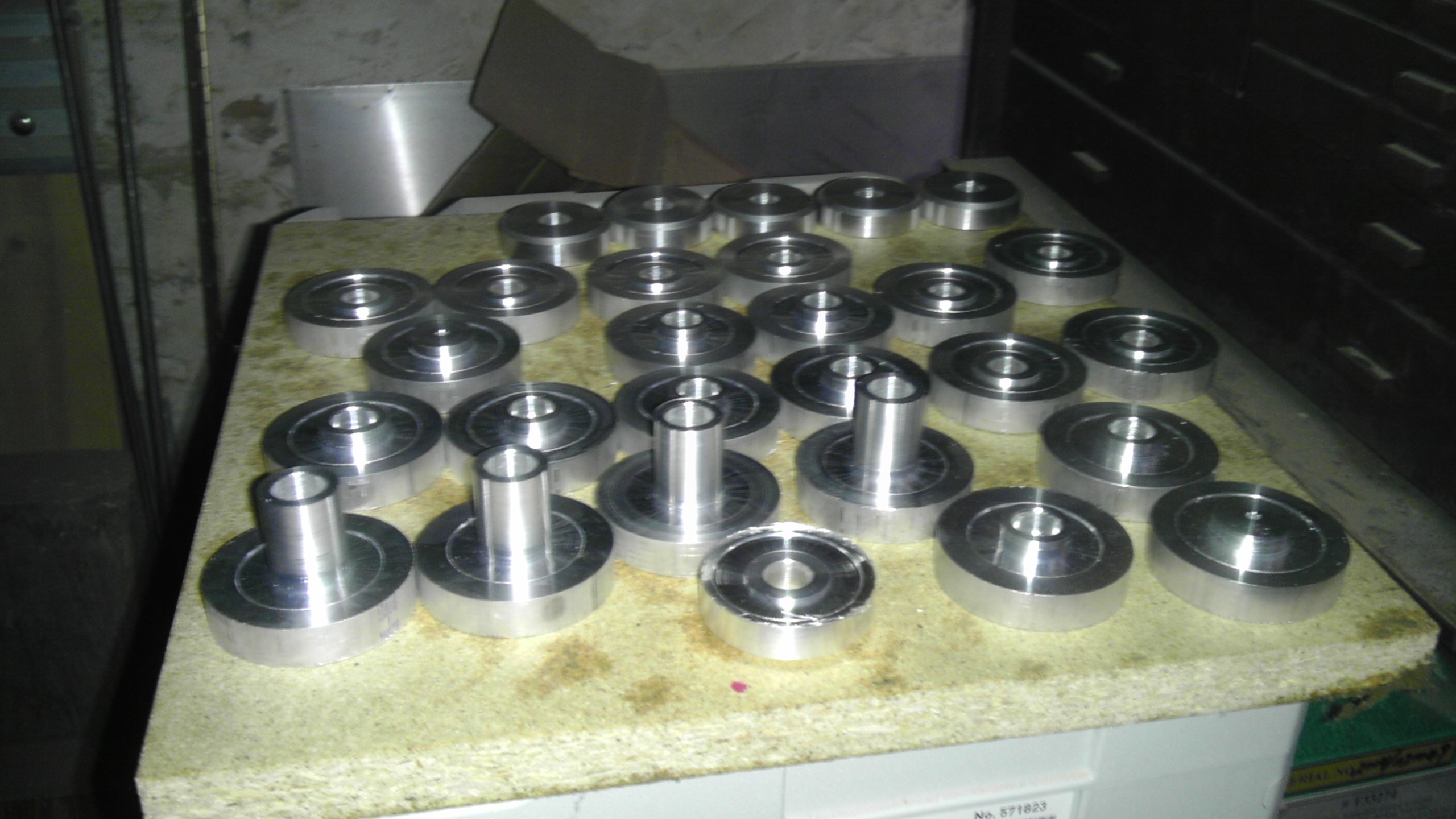
Thank you. I have been working on the mounting hubs for the linear rods for the last few days now. I'm just getting around to learning to use my lathe, and I'm not all that fast at it. These parts are pictured, I still have 2 days left on them including drilling, tapping, prep and powder coat. The frame is still just at the cut lengths stage, I'm trying to get most of the aluminum done first, and out of the way. The advantage of a steel frame is that is is the best practical way to get stiffness, the caviat is that you have to fully engineer your printer before you start, because everything that is attached to many of our printers here is part of a single weldment on my design, so that all control locations, mounting tabs, bolt holes and boring, and wire runs have to be determined as they are all steps in the machining process before I can get to the welding. That said, once the frame is complete, assembly consists of relatively few parts. Since I posted the frame design, I have determined that in order to achieve the multi color capacity I am after, I will add a top to hold the cold ends above the center of the print area so that my Bowden tubes are not asked to angle any more than necessary. But so far, that picture is still in my head. The question is, Will I get around to drawing it before I build it? More soon.
|
Re: Design nearly done - construction started... April 16, 2013 05:31AM |
Registered: 11 years ago Posts: 369 |
NICE !!!
this is my incomplete machine, its made mostly from wood. ive only done up to 1x X-axis gantry, 1x Z-axis frame (1 out of 2). (zero out of 2 Y-axis frame)
3roomlabs.blogspot.sg/2013/04/041-x-axis-revisited.html
[3roomlabs.blogspot.sg]
i have done some mods, so now the X-axis can do 660mm of travel, Z-axis approx 950mm of travel
Edited 3 time(s). Last edit at 04/16/2013 06:01AM by redreprap.
______________________________________
__my mixed bag blog || aka --> [http] || ___ so 3D printing is everywhere ... dont worry, hospitals can now 3Dprint body parts, they will charge you $1million excluding surgical fees ... you will die paying your debts. thats their aim ___ if every patent expires tomorrow, everybody will surely get a 3dprinter and make EVERYTHING ! ____ there is a "DIY-DTG" t shirt printing forum, you can mod an EPSON printer to PRINT like a pro. ___ CNCzone? overly commercialized it seems ___ my country? they will be taxing you for every cm of road you use and track you to your grave using GPS and its government authorized, now they will fire all the traffic wardens instead.___ EEVBLOG? there is only 1 way to do things --> take it apart like a pro
|
Re: Design nearly done - construction started... April 16, 2013 09:13AM |
Registered: 11 years ago Posts: 256 |
That's cool. I myself am a professional joiner, (cabinetmaker, 33 years) but my machine has no wood (nor printed parts) scheduled. I have been working with wood for so long that I need to step away from it entirely for this project. Wood in general has stability issues that you may want to consider in setting up your prints. Chief among them is that when you get your printer warmed up, the wood is going to shrink. For that reason, you might consider slotting any non wooden parts that attach to wooden parts and using fibre or nylon washers under you screws to allow for some sliding. There is no real way to prevent the wood from expanding / contracting. So I wauld also suggest allowing your printer to get fully warmed up, maybe all day before doing any final calibration during the commisioning process. This will allow you to achieve optimum precision for your configuration.
Wood will move in all directions, mostly in width and thickness, less in length. Being made of cells bound by lignen, the wood will attempt to equalize its moisture content to its surroundings, thru osmosis. It is far more sensitive to humidity than it is to temperature. So the reason to give more time for heating is not for temperature, but to set the low humidity condition under which you will be operating. This will bring the wood to around its minimum size, and you may wish to make adjustments at that time, which will bring you close to what will then be a typical operating dimension. Keep me posted.
Wood will move in all directions, mostly in width and thickness, less in length. Being made of cells bound by lignen, the wood will attempt to equalize its moisture content to its surroundings, thru osmosis. It is far more sensitive to humidity than it is to temperature. So the reason to give more time for heating is not for temperature, but to set the low humidity condition under which you will be operating. This will bring the wood to around its minimum size, and you may wish to make adjustments at that time, which will bring you close to what will then be a typical operating dimension. Keep me posted.
|
Re: Design nearly done - construction started... April 17, 2013 01:18AM |
Registered: 11 years ago Posts: 369 |
indeed, this "analogue" character of wood is quite a challenge.
so i have kind of revamped my entire work space into a constant humidity workspace, it is almost always around 60-65% and a temp of about 27-28 degrees.
im not much of a wood working person, its just something that i can use easily, transport home on 2 wheels, have enough tools to work on (just power saws, drills, etc. i dont have large plane saws, table sized cutters, etc)
it is a nice kind of challenge for me to work on this :p
did you see that some folks are printing wood based kinda resin?
Edited 1 time(s). Last edit at 04/17/2013 01:21AM by redreprap.
______________________________________
__my mixed bag blog || aka --> [http] || ___ so 3D printing is everywhere ... dont worry, hospitals can now 3Dprint body parts, they will charge you $1million excluding surgical fees ... you will die paying your debts. thats their aim ___ if every patent expires tomorrow, everybody will surely get a 3dprinter and make EVERYTHING ! ____ there is a "DIY-DTG" t shirt printing forum, you can mod an EPSON printer to PRINT like a pro. ___ CNCzone? overly commercialized it seems ___ my country? they will be taxing you for every cm of road you use and track you to your grave using GPS and its government authorized, now they will fire all the traffic wardens instead.___ EEVBLOG? there is only 1 way to do things --> take it apart like a pro
|
Re: Design nearly done - construction started... April 17, 2013 02:10AM |
Admin Registered: 16 years ago Posts: 13,884 |
... beside wood for handcrafting or wood-dust filled filament for 3D-printing there are other 'woody' methodes too 
Since 1998 I'm occasionally dealing with Tecnaro for their lignin-materials.
Normally they make pellets and sell them for injection moulding expensive parts with a 'burlwood' finish.
I'm dealing with the thermoplastic lignin for 3D-printing or SLS - received some kilogramms of lignin-dust from them but couldn't test this for SLS until now ... maybe in summer, when restarting with the laser-development ...
Viktor
--------
Aufruf zum Projekt "Müll-freie Meere" - [reprap.org] -- Deutsche Facebook-Gruppe - [www.facebook.com]
Call for the project "garbage-free seas" - [reprap.org]
|
Re: Design nearly done - construction started... April 17, 2013 04:12PM |
Registered: 11 years ago Posts: 256 |
|
Re: Design nearly done - construction started... April 19, 2013 01:14AM |
Registered: 17 years ago Posts: 392 |
A massive frame made of cheap steel is something I've been thinking of too. I'll be keeping an eye out for your project Maxx!
Redreprap, the wooden frame will shift with humidity, but unless -everything- else is rock solid on the machine, that might not be much of an issue?
I wonder how these extra long bed machines will print big parts. I would love to be able to build long straight sections of model ship hulls for example.
|
Re: Design nearly done - construction started... April 19, 2013 05:58AM |
Registered: 11 years ago Posts: 369 |
yes indeed, humidity is bad here around the equator regions.
so i have kinda "sealed" off the room. the outside temperature is crazy these few days, i think air temperature is about 38-40 if you are to just stand there and "try" it lol ... madness! i also made a air blower, so that the inside of the entire room is always positive pressure. so far so good, it is also cleaner in the house now that it is all up and running, the heat and the dry dust blowing around outside just overwhelms everything with dirt argh
so i have to keep an air-conditioner on 24/7, this also helps maintain humidity between 60-65%.
yea making larger items has been quite a thing that intrigues me, maybe sub parts that will join up and become a PC chasis, i have always wanted to custom my own chasis, etc etc
im not sure how solid will it be though, but it will def be a interesting challenge :p
this is 1 of those vids that keep me inspired
[youtu.be]
Yvan Wrote:
-------------------------------------------------------
> A massive frame made of cheap steel is something
> I've been thinking of too. I'll be keeping an eye
> out for your project Maxx!
>
> Redreprap, the wooden frame will shift with
> humidity, but unless -everything- else is rock
> solid on the machine, that might not be much of an
> issue?
>
> I wonder how these extra long bed machines will
> print big parts. I would love to be able to build
> long straight sections of model ship hulls for
> example.
Edited 1 time(s). Last edit at 04/19/2013 06:01AM by redreprap.
______________________________________
__my mixed bag blog || aka --> [http] || ___ so 3D printing is everywhere ... dont worry, hospitals can now 3Dprint body parts, they will charge you $1million excluding surgical fees ... you will die paying your debts. thats their aim ___ if every patent expires tomorrow, everybody will surely get a 3dprinter and make EVERYTHING ! ____ there is a "DIY-DTG" t shirt printing forum, you can mod an EPSON printer to PRINT like a pro. ___ CNCzone? overly commercialized it seems ___ my country? they will be taxing you for every cm of road you use and track you to your grave using GPS and its government authorized, now they will fire all the traffic wardens instead.___ EEVBLOG? there is only 1 way to do things --> take it apart like a pro
so i have kinda "sealed" off the room. the outside temperature is crazy these few days, i think air temperature is about 38-40 if you are to just stand there and "try" it lol ... madness! i also made a air blower, so that the inside of the entire room is always positive pressure. so far so good, it is also cleaner in the house now that it is all up and running
, the heat and the dry dust blowing around outside just overwhelms everything with dirt arghso i have to keep an air-conditioner on 24/7, this also helps maintain humidity between 60-65%.
yea making larger items has been quite a thing that intrigues me, maybe sub parts that will join up and become a PC chasis, i have always wanted to custom my own chasis, etc etc
im not sure how solid will it be though, but it will def be a interesting challenge :p
this is 1 of those vids that keep me inspired
[youtu.be]
Yvan Wrote:
-------------------------------------------------------
> A massive frame made of cheap steel is something
> I've been thinking of too. I'll be keeping an eye
> out for your project Maxx!
>
> Redreprap, the wooden frame will shift with
> humidity, but unless -everything- else is rock
> solid on the machine, that might not be much of an
> issue?
>
> I wonder how these extra long bed machines will
> print big parts. I would love to be able to build
> long straight sections of model ship hulls for
> example.
Edited 1 time(s). Last edit at 04/19/2013 06:01AM by redreprap.
______________________________________
__my mixed bag blog || aka --> [http] || ___ so 3D printing is everywhere ... dont worry, hospitals can now 3Dprint body parts, they will charge you $1million excluding surgical fees ... you will die paying your debts. thats their aim ___ if every patent expires tomorrow, everybody will surely get a 3dprinter and make EVERYTHING ! ____ there is a "DIY-DTG" t shirt printing forum, you can mod an EPSON printer to PRINT like a pro. ___ CNCzone? overly commercialized it seems ___ my country? they will be taxing you for every cm of road you use and track you to your grave using GPS and its government authorized, now they will fire all the traffic wardens instead.___ EEVBLOG? there is only 1 way to do things --> take it apart like a pro
|
Re: Design nearly done - construction started... April 20, 2013 12:46PM |
Registered: 11 years ago Posts: 256 |
One nice thing about the steel frame is that materials come out about dead even with the cost of a set of extrusions and printed parts and bolts for a Mendelmax. So with vitimans, I am still around 1200 bucks two colors with a 2.666 FT cubed build envelope. I hope to get to some welding this weekend, though I am awaiting an end mill to finish up some boring. (More pix later today.) I just finished machining my rod adjustment hubs the other day and have started on machining the steel frame parts. Just remember that while the steel itself is not expensive, the fabrication is critical. Once you get done, it is either perfect, or it is scrap metal. My frame is welded, it ends up as one piece. Everything must be drilled accurately. All machining must come up to a few thousandths (it's a frame, not a turbine engine) And absoulely all must be square and level. My adjusters allow for +- 5mm x,y and there is a tension adjustment for each rod end. Because the bigger you go, the more critical everything becomes. For example, let's say that you have a 150mm y axis and you have an error of 1/4 degree, you will probabily get away with it to a point, but stretch that y axis by 400% and now you run into issues. Ultimately, what ever material you choose to assemble your machine, just as important is the degree of care that you put into it, to come out with the best possible prints.
|
Re: Design nearly done - construction started... April 20, 2013 03:19PM |
Registered: 17 years ago Posts: 392 |
Redrep, if you have controled temp and humidity, you are doing well! I find slack and play in the mechanicals is a real issue. That video of the chair is cool. I believe it is made out of structural toothpaste. Fights cavities too!
BTW, I find fumes from ABS extrusion to be an issue, I've got a home made fume extractor cabinet/hood around my printer, and it really helps. I vent exhaust fumes right out the house. I might block off the front with glass this summer when the air conditioner is going, to reduce air flow. Something to think about when everything is closed up with the air conditioner going.
Maxx, yes steel is not expensive, and a basic MIG/GMAW is not expensive either. MIG is so easy to learn too! I see your point about accuracy. With steel, you can always cut out the crooked bit and weld it back in right though...
Looking forward to the photos!
|
Re: Design nearly done - construction started... April 20, 2013 03:49PM |
Registered: 11 years ago Posts: 256 |
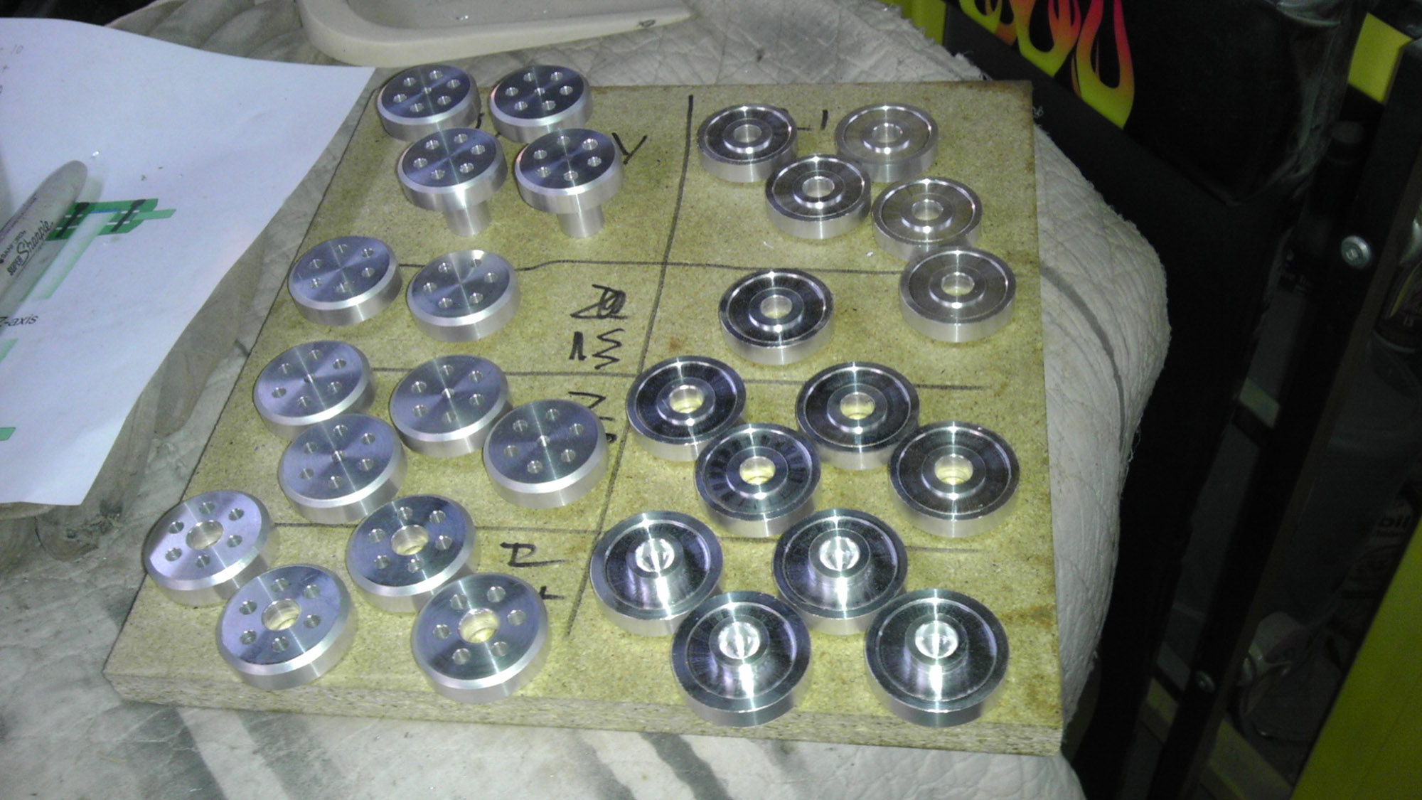
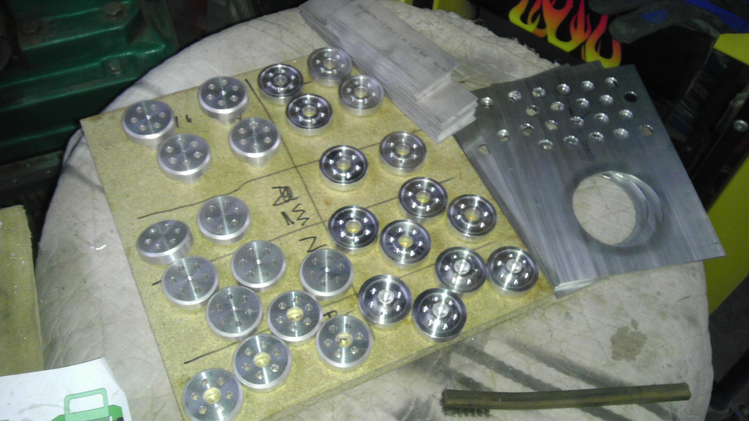
OK so here are a few more shots; I have started drilling for my adjusters, the tube is no problem with a fly cutter but the 1/4 plate just eats boring bars so I have an endmill on order for this week. The Adjusters are finally done, all manual so it took almost a week, and pictured with them are the tops for my PSU / electronic boxes. Almost all the vitimans are here (rods are in the shop).(technically, I guess it's all vitimans?) I'm waiting for about half a dozen more items. I will start welding tomorrow on the first subassmblies for the frame. I want to do all my steel first, and then redo my torch for the aluminum. This will be all TIG welded on a Lincoln 175. (no pulser ) I've got to reread some stuff - welding, powder coating, because it's been awhile. So that's tonight. The good news is as soon as the frame is done, this should go together pretty quick. The bad news is I haven't designed the X axis yet. At least not on paper. I may get everything else innitially assembled first and then do some mockups to determine the optimum geometry given the dimensions I am working with. My concern / objective is to get an 18" wide X carriage to traverse the Y direction at maximum speed without any resistance(as little as possible ) I am using my belts to make a rack and pinnion setup, to avoid having almost 10 feet of belts flapping around. So the way I work, I need to see everything up to that point to end up with an optimal design.
) I've got to reread some stuff - welding, powder coating, because it's been awhile. So that's tonight. The good news is as soon as the frame is done, this should go together pretty quick. The bad news is I haven't designed the X axis yet. At least not on paper. I may get everything else innitially assembled first and then do some mockups to determine the optimum geometry given the dimensions I am working with. My concern / objective is to get an 18" wide X carriage to traverse the Y direction at maximum speed without any resistance(as little as possible ) I am using my belts to make a rack and pinnion setup, to avoid having almost 10 feet of belts flapping around. So the way I work, I need to see everything up to that point to end up with an optimal design.
|
Re: Design nearly done - construction started... April 20, 2013 08:01PM |
Registered: 11 years ago Posts: 369 |
hee hee fume extractor? done. but its kind of a quick fix.
[3roomlabs.blogspot.sg]
Yvan Wrote:
-------------------------------------------------------
> Redrep, if you have controled temp and humidity,
> you are doing well! I find slack and play in the
> mechanicals is a real issue. That video of the
> chair is cool. I believe it is made out of
> structural toothpaste. Fights cavities too!
>
> BTW, I find fumes from ABS extrusion to be an
> issue, I've got a home made fume extractor
> cabinet/hood around my printer, and it really
> helps. I vent exhaust fumes right out the house. I
> might block off the front with glass this summer
> when the air conditioner is going, to reduce air
> flow. Something to think about when everything is
> closed up with the air conditioner going.
>
> Maxx, yes steel is not expensive, and a basic
> MIG/GMAW is not expensive either. MIG is so easy
> to learn too! I see your point about accuracy.
> With steel, you can always cut out the crooked bit
> and weld it back in right though...
>
> Looking forward to the photos!
______________________________________
__my mixed bag blog || aka --> [http] || ___ so 3D printing is everywhere ... dont worry, hospitals can now 3Dprint body parts, they will charge you $1million excluding surgical fees ... you will die paying your debts. thats their aim ___ if every patent expires tomorrow, everybody will surely get a 3dprinter and make EVERYTHING ! ____ there is a "DIY-DTG" t shirt printing forum, you can mod an EPSON printer to PRINT like a pro. ___ CNCzone? overly commercialized it seems ___ my country? they will be taxing you for every cm of road you use and track you to your grave using GPS and its government authorized, now they will fire all the traffic wardens instead.___ EEVBLOG? there is only 1 way to do things --> take it apart like a pro
|
Re: Design nearly done - construction started... April 20, 2013 08:20PM |
Registered: 17 years ago Posts: 392 |
Redrep, cool! You don't need a high flow rate if it is in the right spot. I've used an old range hood as a starting point for a cabinet, and I have a 4 inch duct blowing air out of a hole in the cieling. The flow and noise I higher than needed most of the time, so I want to add a simple fan/light dimmer switch to it.
Maxx, those adjusters look really good. I'm guessing you are using your boring bars on a mill? Why are they wearing out so fast? Chatter... to fast of a speed...? I know nothing about machining, I'm just interested in part because I'm probably going to buy a lathe or milling machine at some point.
Maxx, those adjusters look really good. I'm guessing you are using your boring bars on a mill? Why are they wearing out so fast? Chatter... to fast of a speed...? I know nothing about machining, I'm just interested in part because I'm probably going to buy a lathe or milling machine at some point.
|
Re: Design nearly done - construction started... April 20, 2013 08:22PM |
Registered: 11 years ago Posts: 369 |
speaking of lathes and such, there is chatter in yahoo groups about ceramic tool bits that last beyond metal ones. i wonder if anyone tried those?
______________________________________
__my mixed bag blog || aka --> [http] || ___ so 3D printing is everywhere ... dont worry, hospitals can now 3Dprint body parts, they will charge you $1million excluding surgical fees ... you will die paying your debts. thats their aim ___ if every patent expires tomorrow, everybody will surely get a 3dprinter and make EVERYTHING ! ____ there is a "DIY-DTG" t shirt printing forum, you can mod an EPSON printer to PRINT like a pro. ___ CNCzone? overly commercialized it seems ___ my country? they will be taxing you for every cm of road you use and track you to your grave using GPS and its government authorized, now they will fire all the traffic wardens instead.___ EEVBLOG? there is only 1 way to do things --> take it apart like a pro
|
Re: Design nearly done - construction started... April 20, 2013 11:15PM |
Registered: 11 years ago Posts: 256 |
Yvan Wrote:
-------------------------------------------------------
> Redrep, cool! You don't need a high flow rate if
> it is in the right spot. I've used an old range
> hood as a starting point for a cabinet, and I have
> a 4 inch duct blowing air out of a hole in the
> cieling. The flow and noise I higher than needed
> most of the time, so I want to add a simple
> fan/light dimmer switch to it.
>
> Maxx, those adjusters look really good. I'm
> guessing you are using your boring bars on a mill?
> Why are they wearing out so fast? Chatter... to
> fast of a speed...? I know nothing about
> machining, I'm just interested in part because I'm
> probably going to buy a lathe or milling machine
> at some point.
Well see, the problem is that I know nothing about machining either. It's just go slow and measure carefully. I talked to a machinist today and it seems that the cheap Chinese boring bars are just not quite hard enough for the 1/4 inch steel. I ordered an end mill for the correct size yesterday, I just hope it shows up quickly. The adjusters were a lathe operation untill the holes which were done on a rotary table on the mill. I had to make up acouple of tools to get the job done, including a center finder and a mandril to turn down the parts from 2" to 1 3/4". All in all I'd say there were about 2 dozen steps per each of 28 pieces which took right about a week. I origionally got my lathe and mmill to make up tooling for my cabinet shop, and I've been trying to learn as I go along.
|
Re: Design nearly done - construction started... April 20, 2013 11:20PM |
Registered: 11 years ago Posts: 256 |
redreprap Wrote:
-------------------------------------------------------
> speaking of lathes and such, there is chatter in
> yahoo groups about ceramic tool bits that last
> beyond metal ones. i wonder if anyone tried those?
The problem I ran into was not the cutting edge itself but the shaft of the tool, which was just a bit soft.
|
Re: Design nearly done - construction started... April 21, 2013 02:56AM |
Registered: 11 years ago Posts: 369 |
yea i wont know how good those china made stuff are. some were good.
i bought 8 sample qty of cutters/endmills, i want to try them on the PCB mill i am making.
______________________________________
__my mixed bag blog || aka --> [http] || ___ so 3D printing is everywhere ... dont worry, hospitals can now 3Dprint body parts, they will charge you $1million excluding surgical fees ... you will die paying your debts. thats their aim ___ if every patent expires tomorrow, everybody will surely get a 3dprinter and make EVERYTHING ! ____ there is a "DIY-DTG" t shirt printing forum, you can mod an EPSON printer to PRINT like a pro. ___ CNCzone? overly commercialized it seems ___ my country? they will be taxing you for every cm of road you use and track you to your grave using GPS and its government authorized, now they will fire all the traffic wardens instead.___ EEVBLOG? there is only 1 way to do things --> take it apart like a pro
|
Re: Design nearly done - construction started... April 21, 2013 02:33PM |
Registered: 11 years ago Posts: 256 |
I have the Harbor Freight 12x36 lathe and the mill drill. When I bought them they were about half of what they cost now. I always wondered how it was that jet charged twice as much for the exact same machines. Used to their capabilities, they are good machines, accurate and forgiving of a silly mistake or two here or there. For me, things like drills and end mills are basically disposable items, so as long as you mind your speeds and feeds, and lubricate as needed, the Chinese stuff is just fine, especially at the price. You just have to know when it pays to buy cheap, and when it pays to spend more, if the same tool has 2 prices for 2 paint jobs, go cheaper. If you need to use something every day, and things like proper design, ergonomics, and specific capabilities are important, then you have to go with the better made tool. I do not like Chines wrenches (no name) or screwdrivers (at all) do to fit and duribility issues repectively. But most of my wrenches are 25 years old, unfortunitly there are few high quality affordable options today versus back then. I'd like to see pics of your project.
|
Re: Design nearly done - construction started... April 23, 2013 10:29AM |
Registered: 11 years ago Posts: 256 |
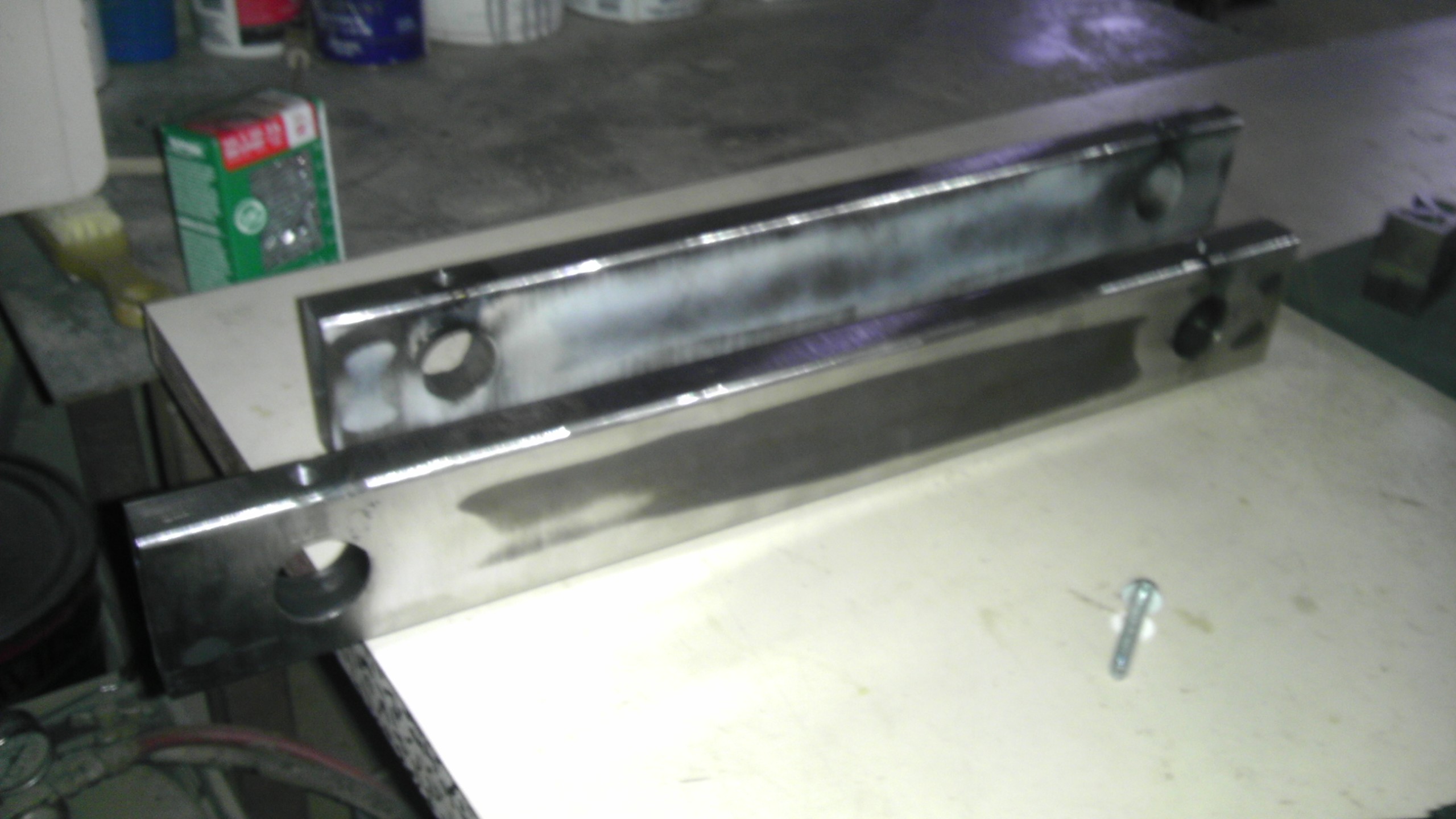
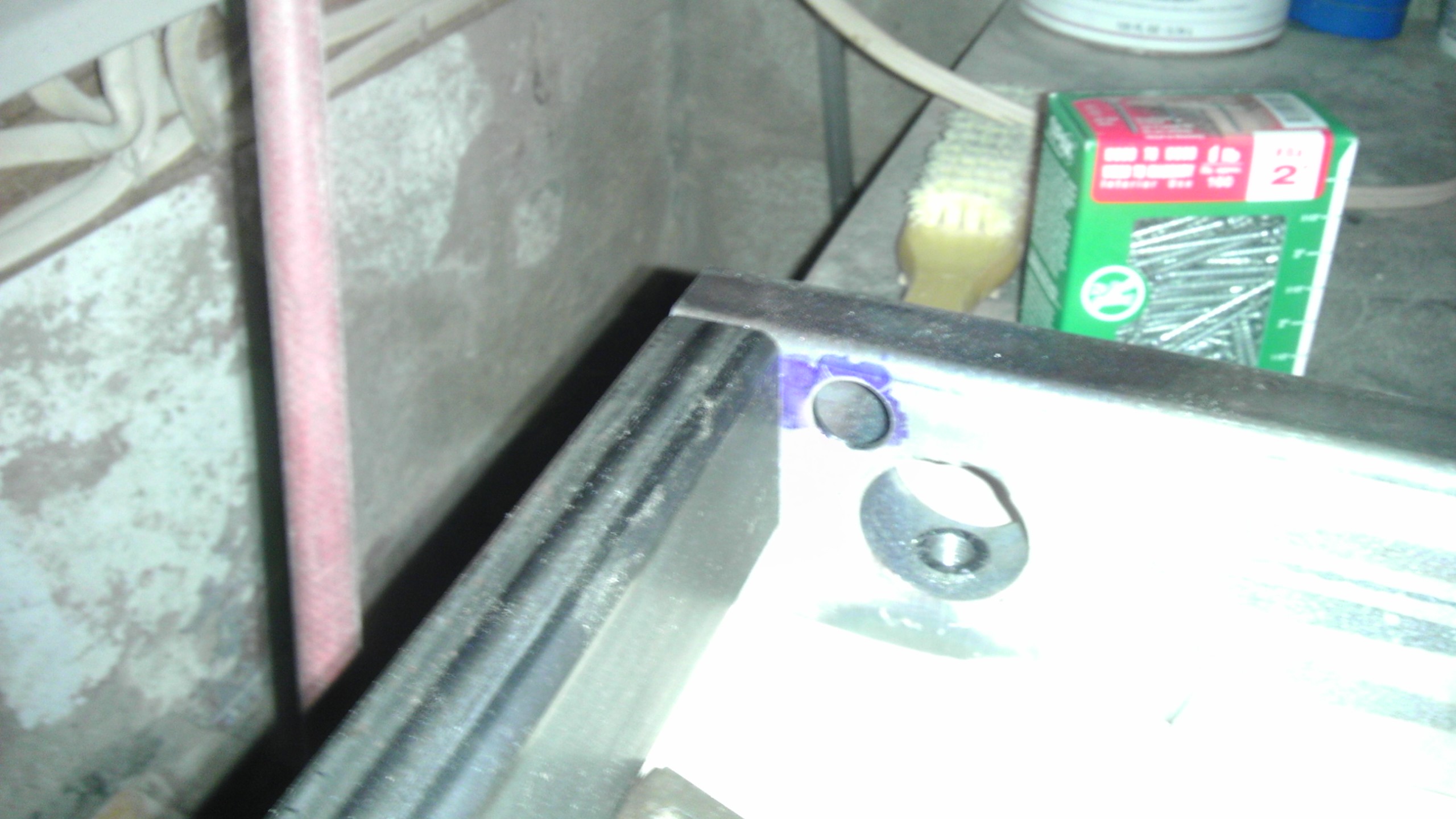
Slow going the last couple of days, which is what always happens when you need tooling late on a Friday afternoon. I did however manage to start some preliminary welding on the frame. What you are looking at is the upper ends with the reinforcements for the Y adjusters welded in, as well as the pieces for the Y vertical adjustment screws. There would be no end of aggravation trying to level the Y axis rods with out them. Since my design is evolving, I am moving slowly on welding up this frame - it's 10 times harder to drill holes when it's assembled.
Most of the parts are here, though I still need to order the rest of the fasteners for the electronics, motors ect. I also have to determine the final XY dimensions so I can get the remaining materials for the heat bed. I do know roughly what they are, but before I order glass, etc.... More frame pix next.
Most of the parts are here, though I still need to order the rest of the fasteners for the electronics, motors ect. I also have to determine the final XY dimensions so I can get the remaining materials for the heat bed. I do know roughly what they are, but before I order glass, etc.... More frame pix next.
|
Re: Design nearly done - construction started... April 25, 2013 06:51PM |
Registered: 11 years ago Posts: 256 |
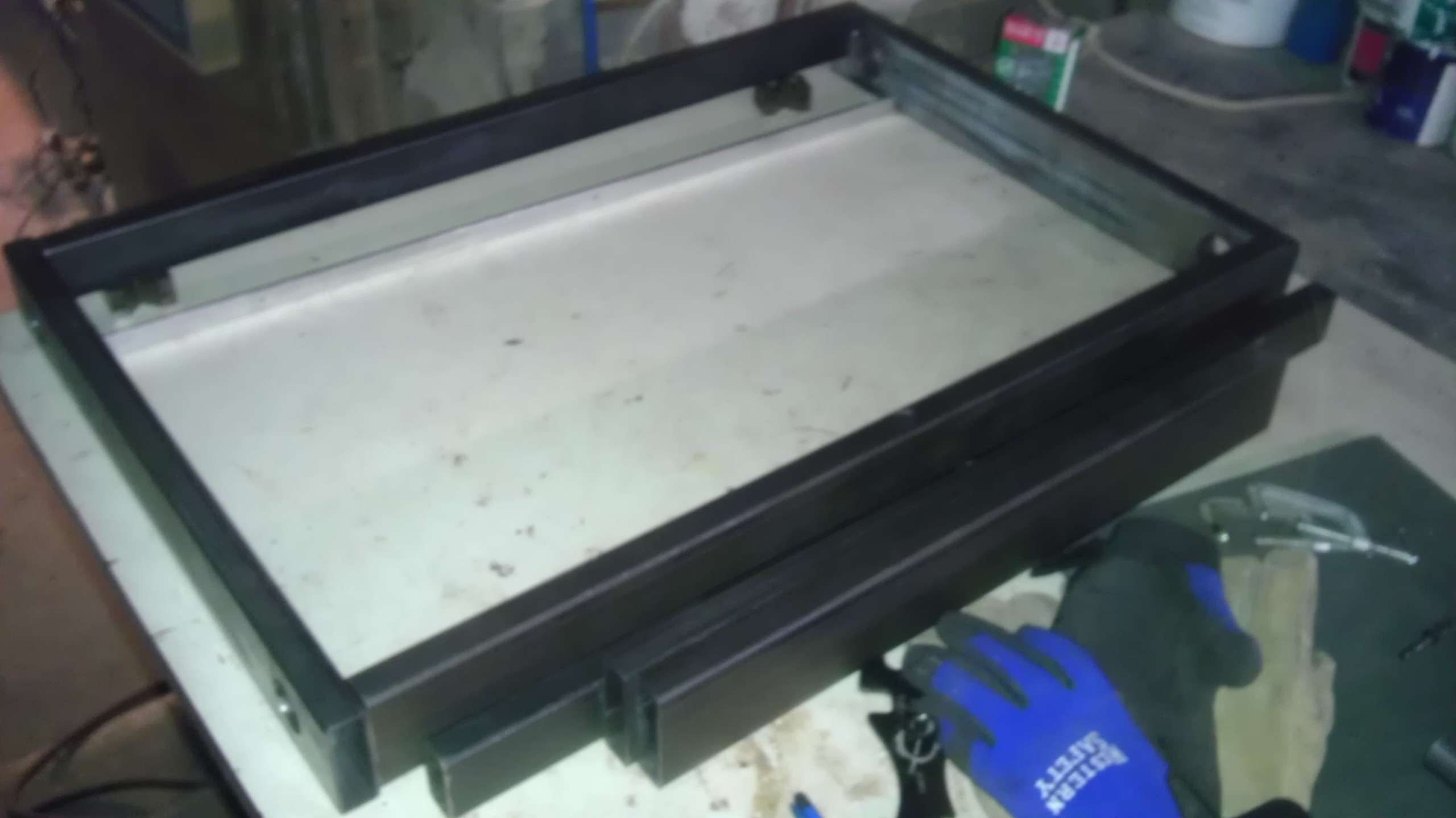
A couple more pics; the process of drilling the frame members is underway. Here you can see the parts for the upper frame laid out with the drag rail setting inside and some of the bottom bits outside, as well as a close up of a wire drop. This won't be grommeted, instead, it has been smoothed and polished all the way around to prevent chafing. Also over the last few days I have been getting closer to finalize the design of the moving parts. I have determined that while the Y (long) axis will definately be a rack and pinnion setup, the X axis will be belt driven. This way there are no motors on the extruder carriage. This printer will be big and heavy, but fast, (like a Bently)
|
Re: Design nearly done - construction started... April 26, 2013 02:17AM |
Registered: 17 years ago Posts: 392 |
|
Re: Design nearly done - construction started... April 26, 2013 03:53PM |
Registered: 11 years ago Posts: 256 |
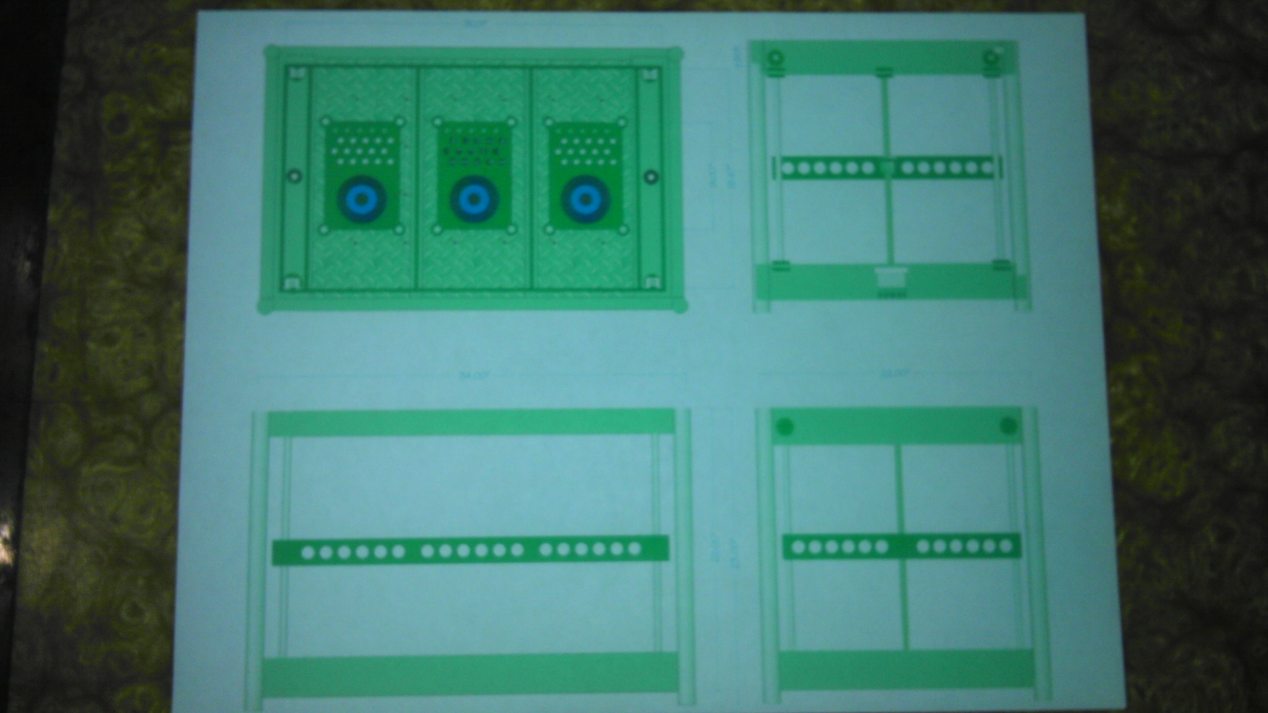
The adjusters are the dark green bits at the corners. You are seeing the upper frame members which hold the Y axis (long). The bed is the Z axis. Upper left drawing is the base from above, showing electrical and psu boxes. There is also going to be an elevated platform for the extruder motors. This is still in design, as it is a critical element to limiting resistance to the hotend carriage from the Bowden tubes. Since I ultimately want to end up with 7 extruders, (ultimately means not before I begin calibration The geometry of the tube setup is the most demanding engineering challenge on this machine, and the desired number of colors is a key factor in its overall design. The trick is to minimize at all times the angles of the tubes, and it is imperative that they in no time are allowed to straighten out. Even though the tubes are somewhat soft, if they go straight, then they will cause ripples as they pass the bending moment. At the same time, it is important to keep the angles minimal to avoid binding. As to the electronic means to control 7 extruders, I am looking at a couple of options, either encoding/decoding each extruder pair, or running the hotends as cool as will print a given filiment reliably, and then just make before break switching the individual pololus, or doing something similar. Either way, it will require I build my own ramps extension board. I don't mind running a bunch of wires to my motors which will be stationary, but I need to minimize wire runs to the carriage. 
The geometry of the tube setup is the most demanding engineering challenge on this machine, and the desired number of colors is a key factor in its overall design. The trick is to minimize at all times the angles of the tubes, and it is imperative that they in no time are allowed to straighten out. Even though the tubes are somewhat soft, if they go straight, then they will cause ripples as they pass the bending moment. At the same time, it is important to keep the angles minimal to avoid binding. As to the electronic means to control 7 extruders, I am looking at a couple of options, either encoding/decoding each extruder pair, or running the hotends as cool as will print a given filiment reliably, and then just make before break switching the individual pololus, or doing something similar. Either way, it will require I build my own ramps extension board. I don't mind running a bunch of wires to my motors which will be stationary, but I need to minimize wire runs to the carriage.
|
Re: Design nearly done - construction started... April 26, 2013 05:51PM |
Registered: 17 years ago Posts: 392 |
Okay, I see now. If you had a small basic 3D printer up and running now, you could build a lot of the small bits for the mega printer with it!
BTW have you looked into triangulation? The welded steel box frame will have a few frequencies at which it will vibrate, and that might affect the surface finish and fine detail of the prints. The faster things move the more of an issue this becomes.
When you say all the wires to the carriage, you mean heaters and temp sensors multiplied by 7?
|
Re: Design nearly done - construction started... April 26, 2013 06:30PM |
Registered: 11 years ago Posts: 256 |
The vertical members of the frame are cylinders and will be seam welded along the vertical edge as well as around the perimeter so that should act like triangulation. The frame, other than the couple of wire runs will be filled with sand and / or coated internally where I cant put sand. I also have designed the Y and Z axis' to be a suspension mount to minimize the amount of vibration (LF, there will be more HF but probably not bad)This mount uses adjustable tension to firmly mount the rods in these axis. I may use Dynomat on the big flat metal surfaces. This is an automotive product used to dampen the body panels on cars to improve insulaton of road noise. It is basiclly a ruberized sheet with a strong heat resistant adheisive and a foil backing.
As to the carriage wires, I am looking into ways to multiplex the signals to minimize the number of wires. I would think the circuitry to do it will be rather small and light.
As to the carriage wires, I am looking into ways to multiplex the signals to minimize the number of wires. I would think the circuitry to do it will be rather small and light.
|
Re: Design nearly done - construction started... April 26, 2013 06:30PM |
Registered: 11 years ago Posts: 381 |
Awesome build bro. You should nickname it Sherman. You know like the tank. That thing sure is solid and I can tell your taking your time to build it right instead of just rushing through the process. I tip my hat to you and I can't wait to see more.
--------------| For Everything |--------------------------
Check it out here:
[reprapsquad.wordpress.com].
---------| For Everything Prototype Related |------
Now featuring comp case mods:
[RepRapLab.wordpress.com]
--------------| Find us at Twitter|------------------------
@REPRAPSQUAD (RS Main)
[mobile.twitter.com]
@REPRAPSQUADHQ (ProtoLab)
[mobile.twitter.com]
|
Re: Design nearly done - construction started... April 26, 2013 06:40PM |
Registered: 11 years ago Posts: 381 |
I did a similar thing with my custom made Printrbot. I put my whole reprap platform on a suspension like setup. So it auto levels the whole printer and if there are any bumps the whole machine will move in unison. It doesn't move or vibrate much due to the reinforcements I've done. I like the sand idea, keep up the good work.
--------------| For Everything |--------------------------
Check it out here:
[reprapsquad.wordpress.com].
---------| For Everything Prototype Related |------
Now featuring comp case mods:
[RepRapLab.wordpress.com]
--------------| Find us at Twitter|------------------------
@REPRAPSQUAD (RS Main)
[mobile.twitter.com]
@REPRAPSQUADHQ (ProtoLab)
[mobile.twitter.com]
|
Re: Design nearly done - construction started... April 26, 2013 08:17PM |
Registered: 11 years ago Posts: 256 |
Thanks, RS. Yes, I am taking my time, because there are a lot of details that have to go into this frame, before all the parts get welded. After that, accuracy goes out the window, and it is several times harder to drill. So I need to determine where every stationary part, every bolt, all sand holes, on and on. It is definitly a lot to think about. While I have the drawing, it is at best incomplete, since I need to see and feel things to be sure it all works. I won't lie to you, I really want to get past this part, but it's always faster to do it right slowly than to redo it quickly.
|
Re: Design nearly done - construction started... April 26, 2013 10:10PM |
Registered: 17 years ago Posts: 392 |
I can't quite figure out what you guys are refering to with this suspension approach. I need photos or something.
I guess Dynamat would work! If you are boxing in some sides of the frame with metal panels, that would provide triangulation, but I'm not sure if that is what you have in mind.
BTW, I have heard of epoxy and granit powder used as a filler to dampen and stiffen machine frames. Also concrete. Poured in the same way sand would be, but better it seems.
About the cabling to the X carriage, my impression is that would cause much less ressistance than the Bowdens. For a short run of wire, the guage is not that big or stiff, especially if nicely laid out.

Sorry, only registered users may post in this forum.