Design nearly done - construction started...
Posted by Maxx Mayhem
|
Re: Design nearly done - construction started... May 25, 2013 09:06PM |
Registered: 10 years ago Posts: 24 |
|
Re: Design nearly done - construction started... June 06, 2013 07:13PM |
Registered: 11 years ago Posts: 256 |
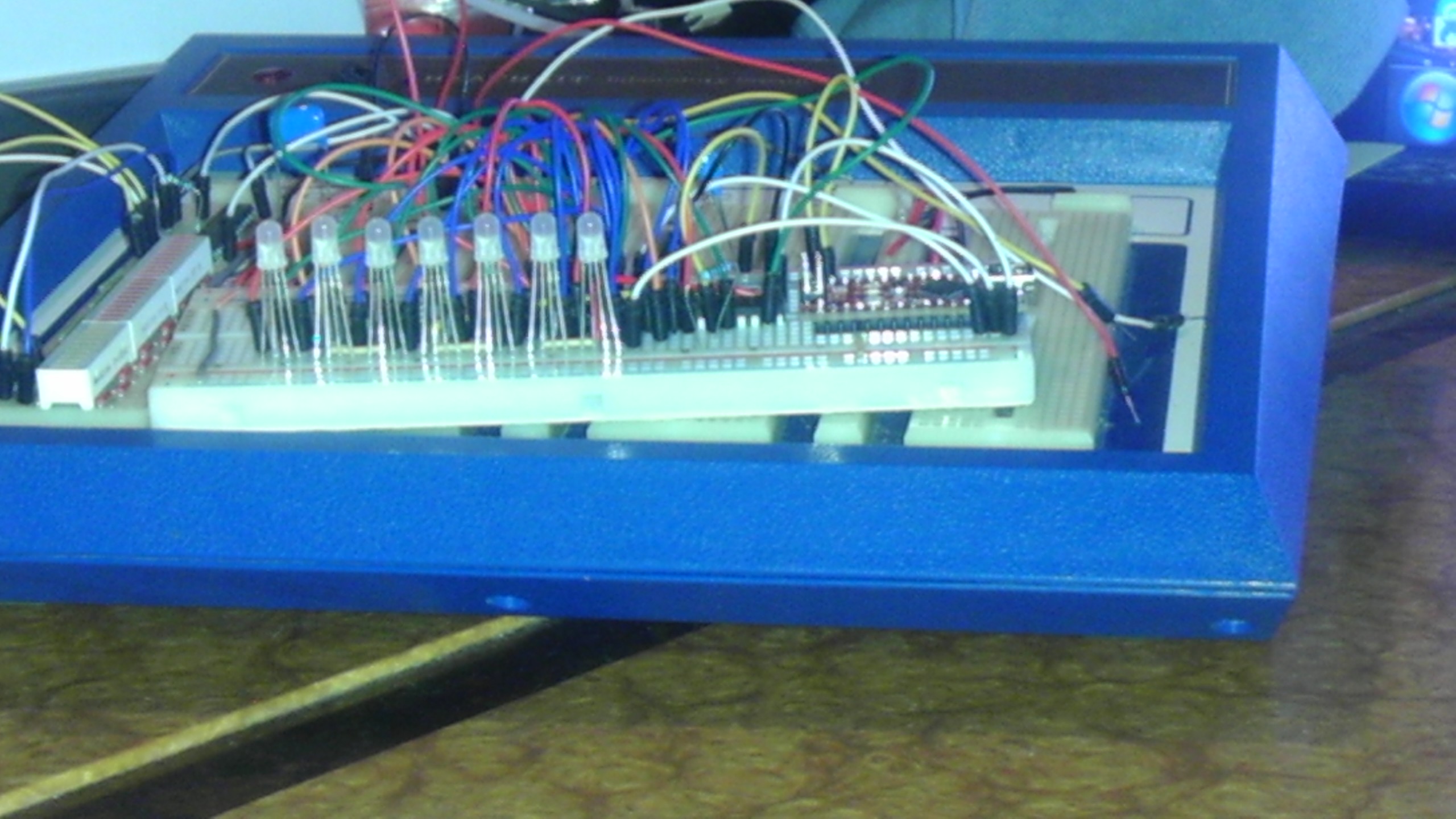
So what ever happened to... After a couple of busy weeks in the shop doing customer work, I'm finally back on the GT-7 and today I began machining the heavy corner members of my frame. It took some doing, but I finally determined the optimum way to clearance for my adjusters, while giving the maximum welding real estate for the most stiffness. I plan to complete machining and weld this up tomorrow, there will be pix then. Also now I am building up parts for the three electronics chassis that will support the 3 PSUs, Ramps, 6064 drivers for the Z mots, and the annunciator circuitry which will monitor this printer, and aid me in monitoring its operation. I'll use multi color LEDs, segment LEDs and numerical LEDs to monitor extruder operation, axis position and temperatures, as well as elapsed time. A couple of pieces are shown, I got an extra little arduino for testing. Making the circuit is easy, programming it is the fun part. (I've exactly zero experience in each, so thanks to Mr Banzi!)Stay tuned, If I get the welding done in the next day or so, things will start to get exiting.
|
Re: Design nearly done - construction started... June 06, 2013 07:55PM |
Registered: 10 years ago Posts: 24 |
WOW! 
Each and every time I read some new step you got done I get myself more eager to see your printer completely done and working! Actually I get excited to build my own..however I have no experience at all..
Do you think that to get a tutorial over the web would be a go? Did you create any documentation about your printer to share?
Congrats for the nice work! BTW get my WOW again for your wonderful progress and thanks for update your progress and keep us motivated into start as well.
I will keep my eyes over this thread looking forward for more news!
Cheers
Each and every time I read some new step you got done I get myself more eager to see your printer completely done and working!
Actually I get excited to build my own..however I have no experience at all..Do you think that to get a tutorial over the web would be a go? Did you create any documentation about your printer to share?
Congrats for the nice work! BTW get my WOW again for your wonderful progress
and thanks for update your progress and keep us motivated into start as well.I will keep my eyes over this thread looking forward for more news!
Cheers
|
Re: Design nearly done - construction started... June 06, 2013 09:48PM |
Registered: 11 years ago Posts: 369 |
what is the function of the LED? visual monitor for fwd/rev ofstepper output? at the output stage or the logic stage?
______________________________________
__my mixed bag blog || aka --> [http] || ___ so 3D printing is everywhere ... dont worry, hospitals can now 3Dprint body parts, they will charge you $1million excluding surgical fees ... you will die paying your debts. thats their aim ___ if every patent expires tomorrow, everybody will surely get a 3dprinter and make EVERYTHING ! ____ there is a "DIY-DTG" t shirt printing forum, you can mod an EPSON printer to PRINT like a pro. ___ CNCzone? overly commercialized it seems ___ my country? they will be taxing you for every cm of road you use and track you to your grave using GPS and its government authorized, now they will fire all the traffic wardens instead.___ EEVBLOG? there is only 1 way to do things --> take it apart like a pro
|
Re: Design nearly done - construction started... June 07, 2013 11:03AM |
Registered: 11 years ago Posts: 256 |
Eric, thanks. I have no experience in this either, but I have found that with all of the information both here and in the wiki, there is a good amount of material to start from in creating a new design. For the moment, I am basically documenting my progress right here, and will supplement that with more details as they become available, and as time permits. As to a tutorial, that could prove useful I suppose as dealing with calibration. As to construction, again, I'll continue to detail that here as best I can
Redreprap, the LEDs will cover several items; There will be digit individual digit displays for elapsed time, ambient temp, upper hotend cluster temp, and bed temp. There will be chaser strips to display approximate axis position as the X and Y axis are somewhat hidden behind the frame rails. Then there will be a set of LEDs for the extruders which will report warming, ready, in use and malfunction. I am still working on details of sensor arrangement, but these will report on activity at the physical layer relative to the software. In other words, if there is a discrepancy between software commands and actual current condition, I'll get an indication. This really isn't a luxury item in trying to calibrate a printer of this size. Although it will be capable of production runs, its prime function is large architectural / historical models with huge footprints. To make this work, I'll need a good reading on everything. If you can control temperatures, you will get the best results.
Redreprap, the LEDs will cover several items; There will be digit individual digit displays for elapsed time, ambient temp, upper hotend cluster temp, and bed temp. There will be chaser strips to display approximate axis position as the X and Y axis are somewhat hidden behind the frame rails. Then there will be a set of LEDs for the extruders which will report warming, ready, in use and malfunction. I am still working on details of sensor arrangement, but these will report on activity at the physical layer relative to the software. In other words, if there is a discrepancy between software commands and actual current condition, I'll get an indication. This really isn't a luxury item in trying to calibrate a printer of this size. Although it will be capable of production runs, its prime function is large architectural / historical models with huge footprints. To make this work, I'll need a good reading on everything. If you can control temperatures, you will get the best results.
|
Re: Design nearly done - construction started... June 07, 2013 05:12PM |
Registered: 11 years ago Posts: 256 |
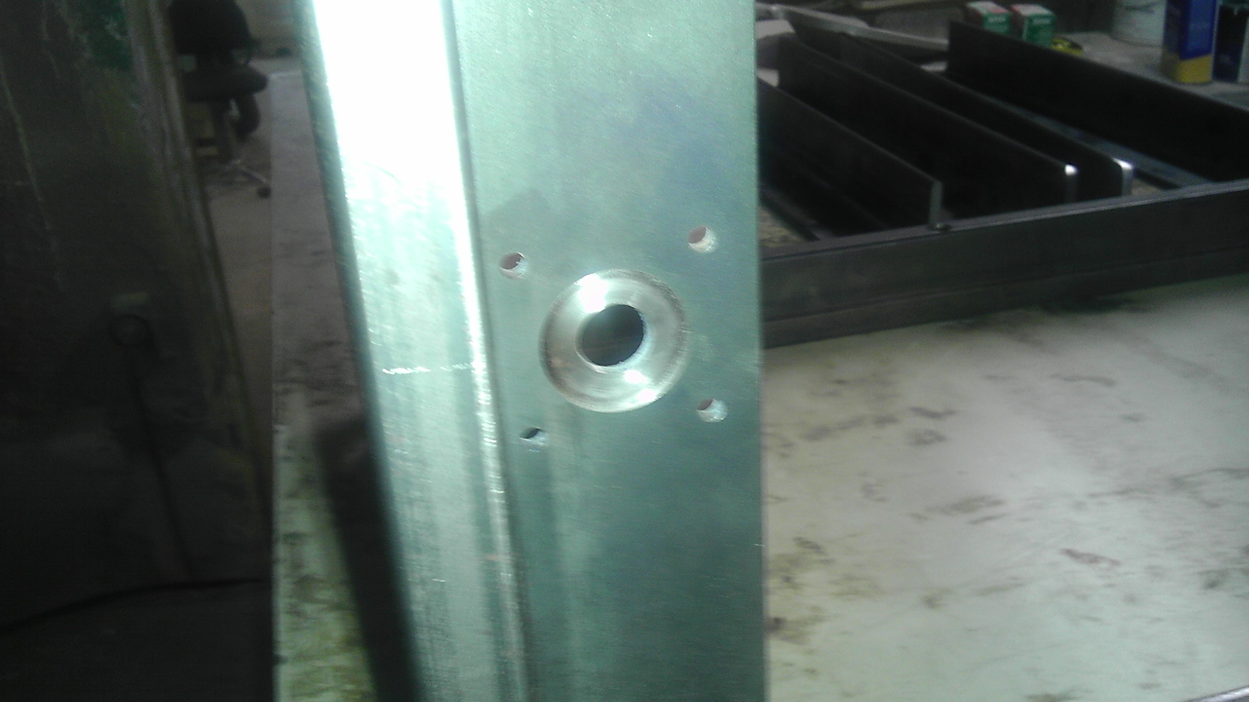
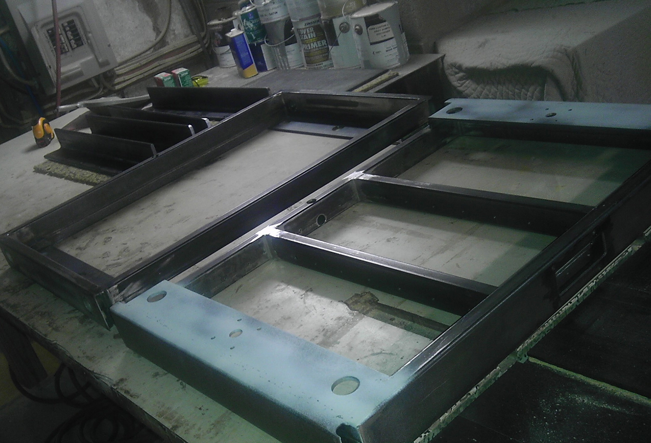
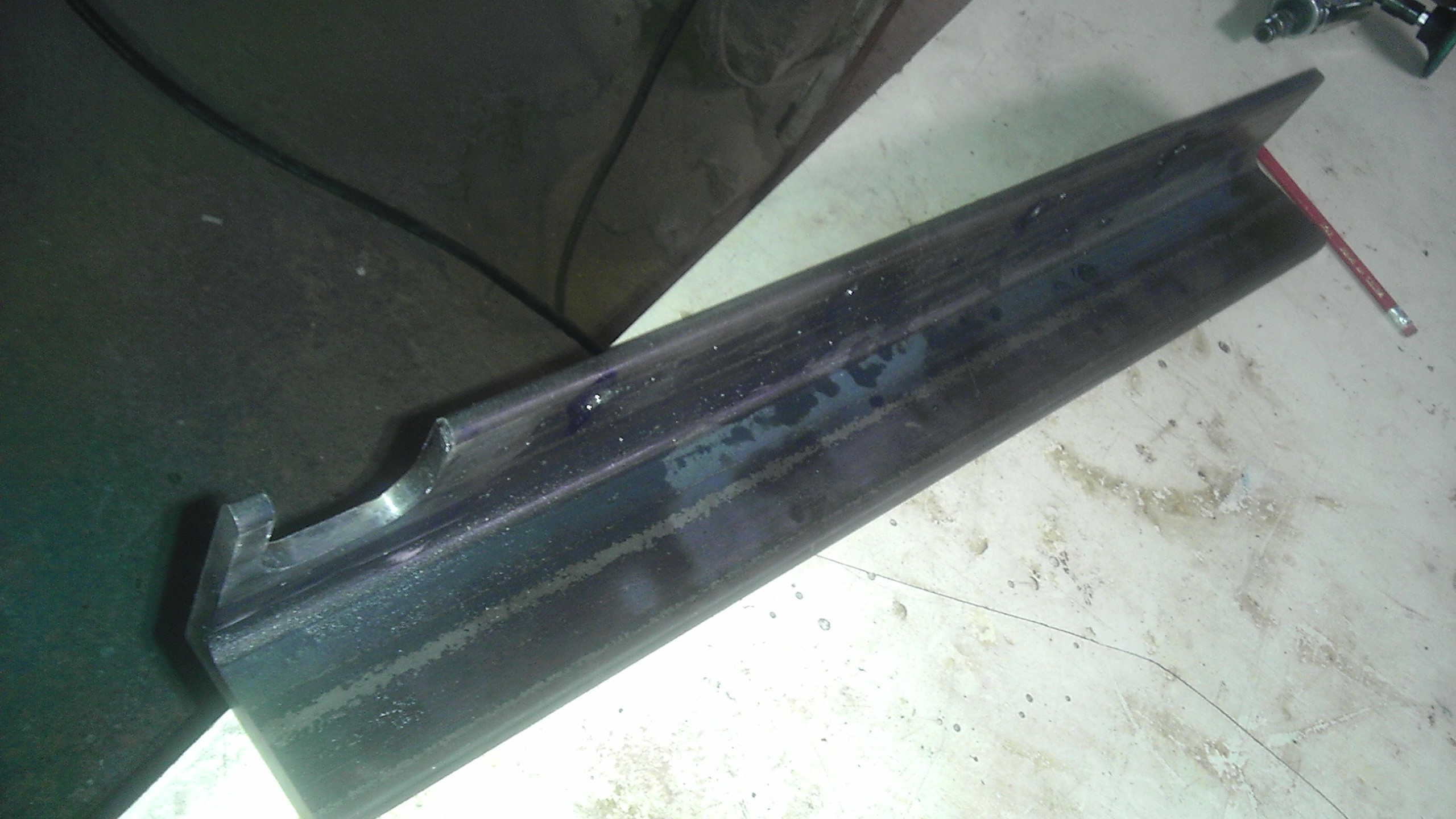
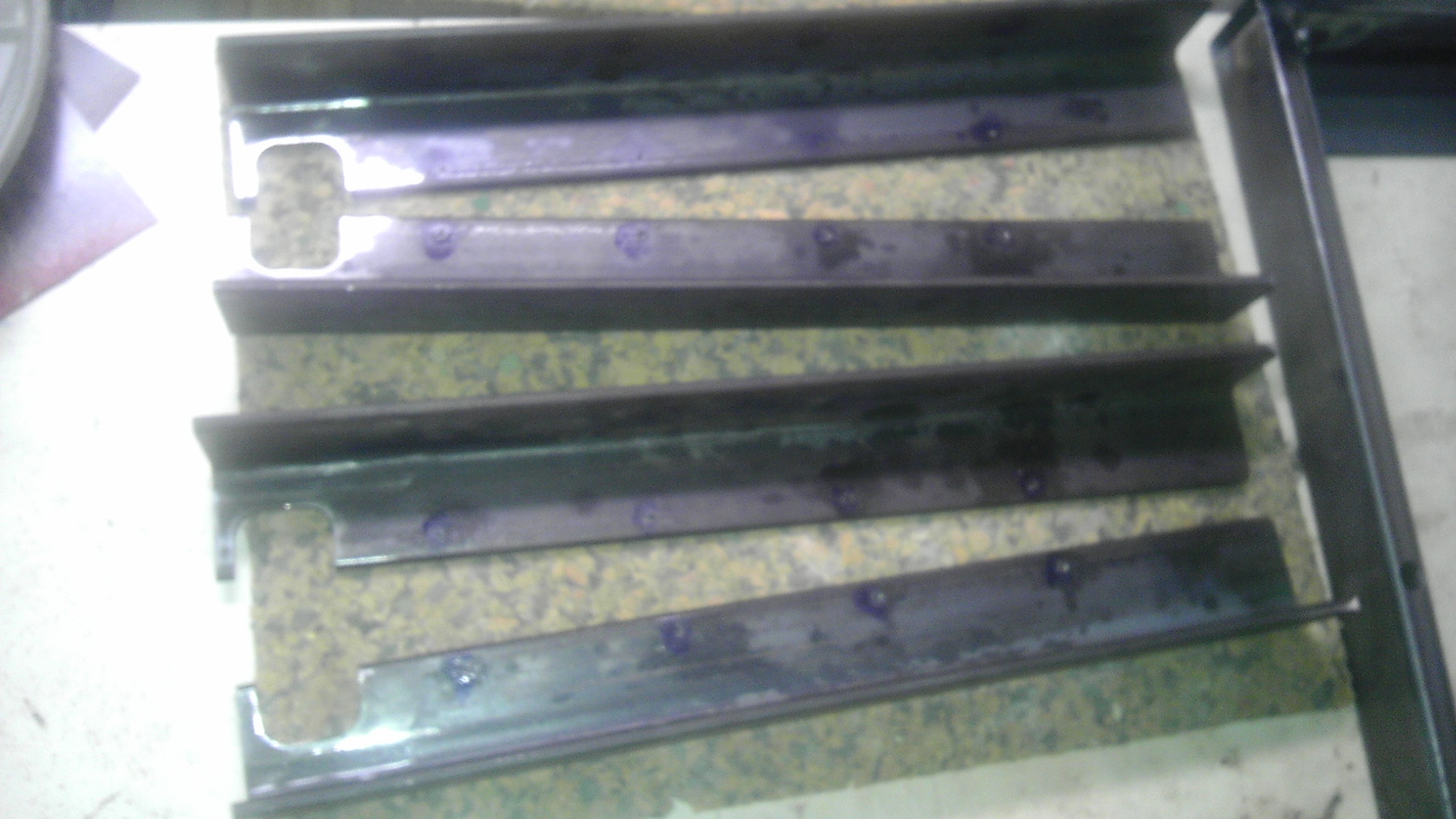
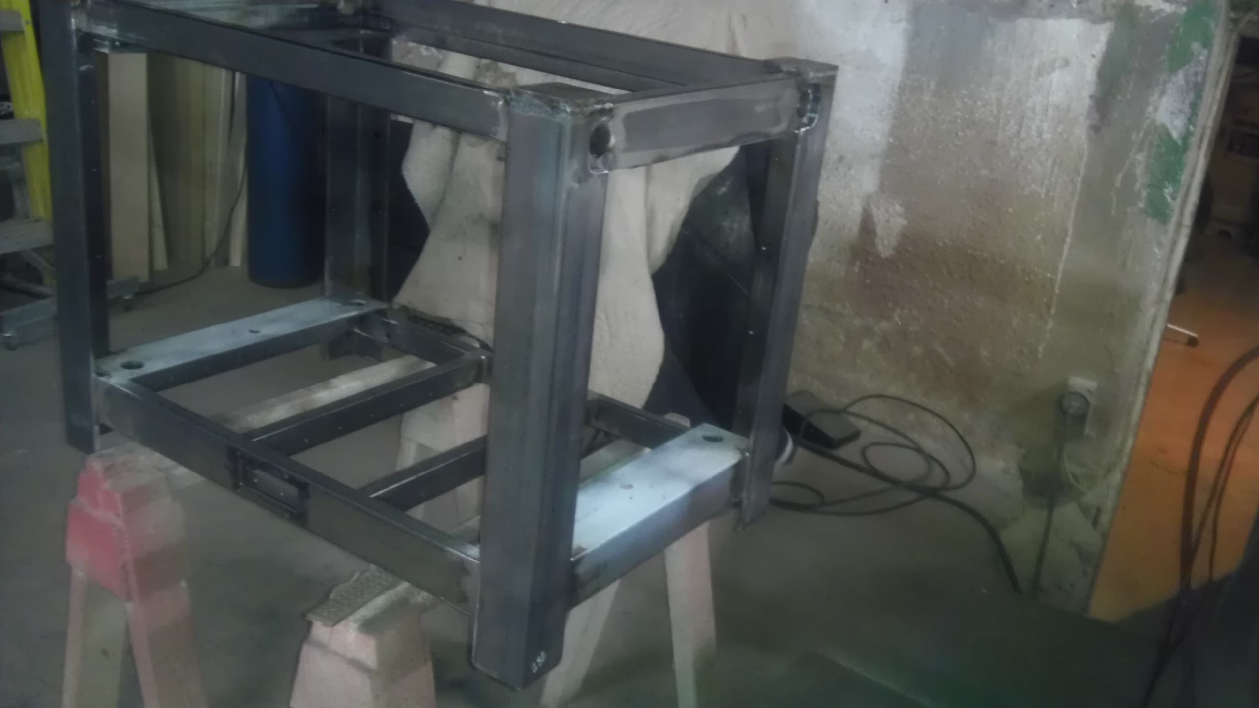
All of the parts for the frame are now ready to be assembled - welding gets done tomorrow. Here are all the parts lined up, the legs, a leg close up and a close up of the mounting points for the nema23 Z motors. The notches in the legs accommodate the Y axis adjusters, legs are tapped for installation of the enclosing panels. This frame is the most labor intensive part of the whole project. I would estimate 100 - 125 hours in total. In production, I would likely opt to machine the top and bottom frame sections from solid billets of aluminum, at approximately the same dimensions. Once welded up, I will media blast and paint the frame right away, and begin getting the aluminum parts - adjusters, electronics housings, stage,carriage etc together and powder coated, so I can get this assembled. 
|
Re: Design nearly done - construction started... June 08, 2013 07:25PM |
Registered: 11 years ago Posts: 256 |
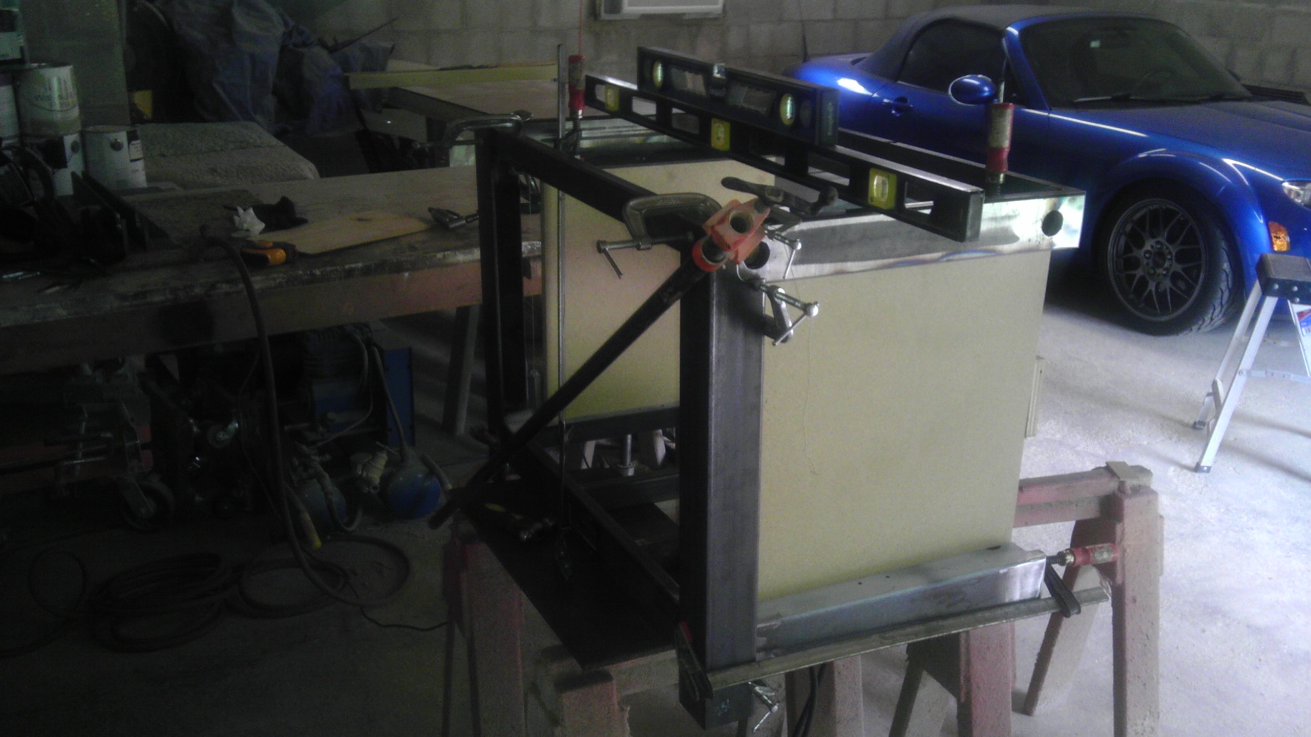
Now we're gettin' someplace... I got about half the frame final assembly welded up today, I hit all the corners so it is set, plumb, level and square. Don't ask how long that took, suffice it to say the rest of the welding should go pretty quick. After initially migging the tack welds, I decided tig was the way to go, and with my new, adjustable helmet, it proved to be quite a bit easier going than a couple of weeks ago. So here are some pics, including a shot of the plum bob dead on, and the whole frame. I have 2 levels because the shorter one is more accurate, it just wont bridge the width...
|
Frame welding complete.... June 17, 2013 04:56PM |
Registered: 11 years ago Posts: 256 |
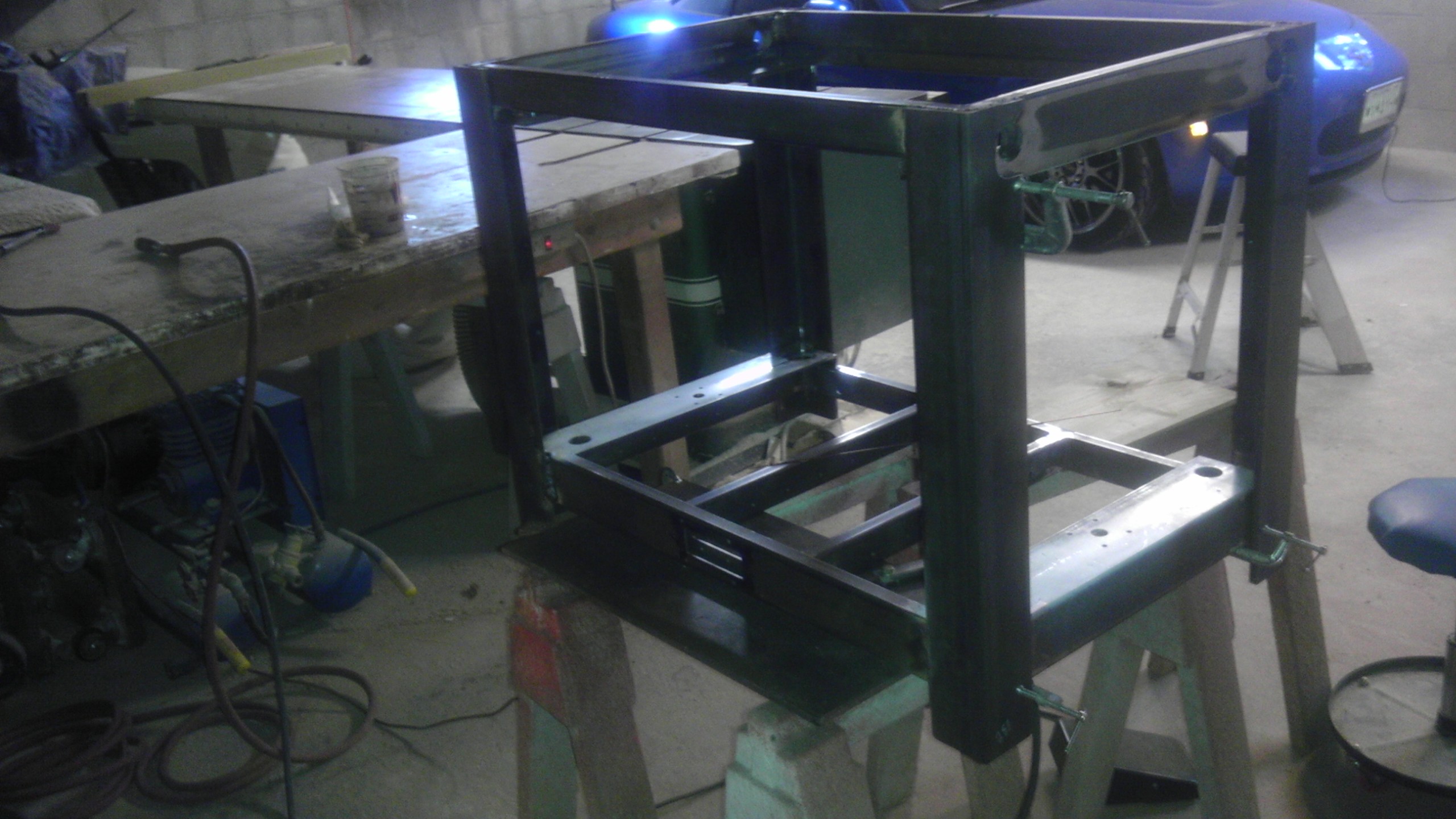
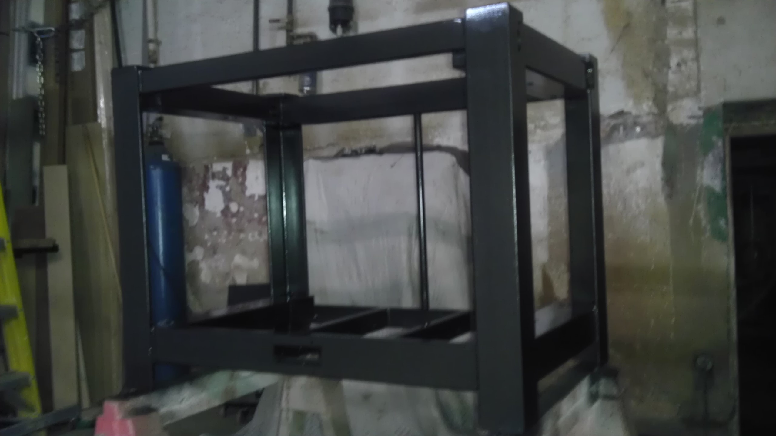
Just a bit of final grinding and prep before finishing. This component is by far the most complicated part of the project, as it encompasses all of the design and engineering up front. You can see all adjuster and motor holes, all of the screw holes for electrical chassis mounting, the upper frame (TB and more are drilled and tapped, all machining processes are done at this point because all had to be complete prior to assembly. All in all, 34 pieces of 1/8, 1/4, and 3/8" thick steel are brought together into a single rigid weldment, which is trued in 3 dimensions. Still, there is approx 14 mm total adjustment allowed by the rod adjustment hubs, which will be added soon in the build. Here is a pic of the frame, ready for a few last bits of grinding, in its raw glory.
and more are drilled and tapped, all machining processes are done at this point because all had to be complete prior to assembly. All in all, 34 pieces of 1/8, 1/4, and 3/8" thick steel are brought together into a single rigid weldment, which is trued in 3 dimensions. Still, there is approx 14 mm total adjustment allowed by the rod adjustment hubs, which will be added soon in the build. Here is a pic of the frame, ready for a few last bits of grinding, in its raw glory.
|
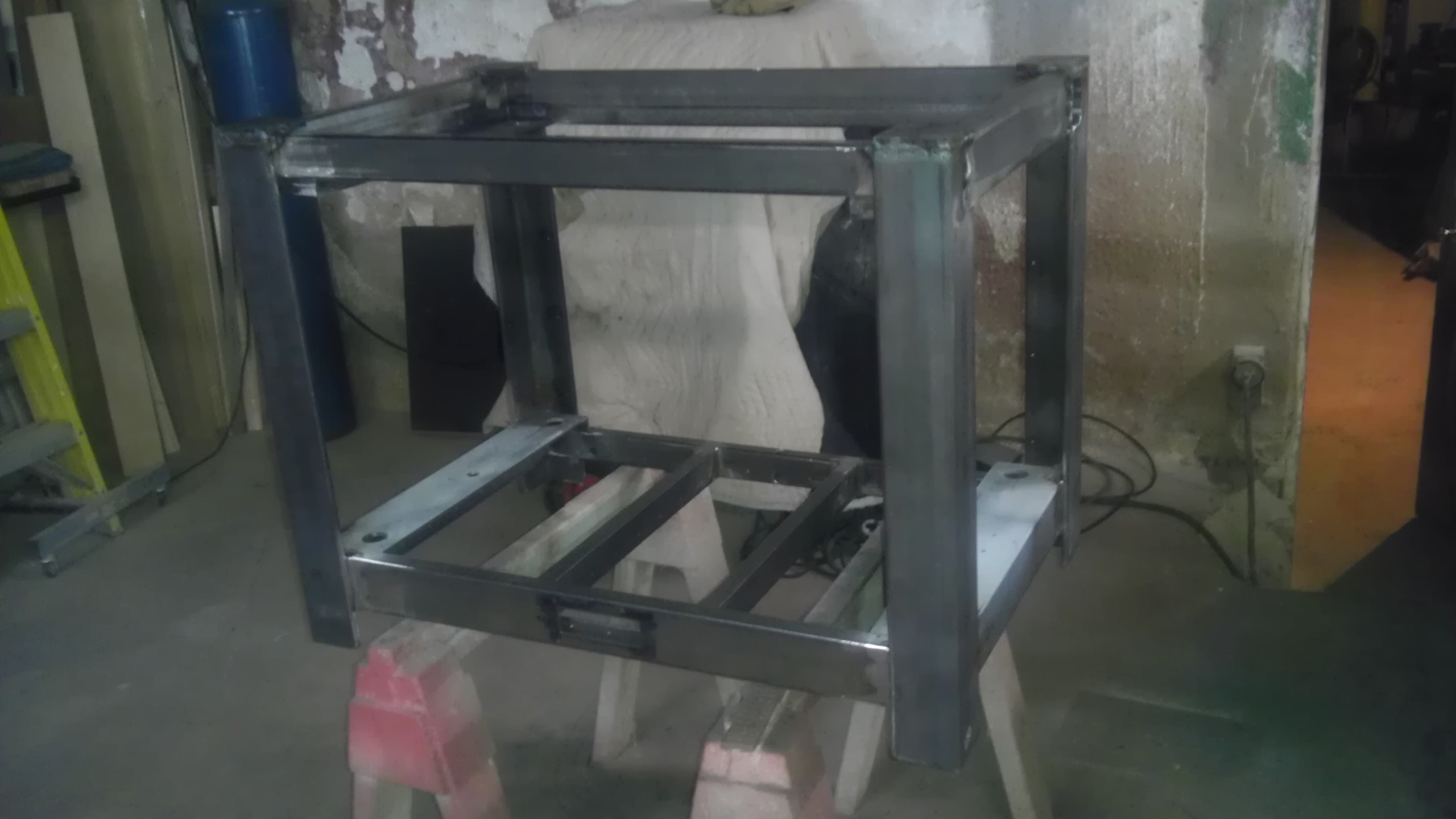
Finally... The frame is complete June 19, 2013 09:36AM |
Registered: 11 years ago Posts: 256 |
|
Re: Design nearly done - construction started... June 19, 2013 06:13PM |
Registered: 17 years ago Posts: 392 |
|
Re: Finally... The frame is complete June 19, 2013 07:44PM |
Registered: 10 years ago Posts: 474 |
I totally agree with you with frame stiffness the larger you go you have to go absurdly stiff here is a couple pictures of my build
Edited 1 time(s). Last edit at 06/20/2013 10:52AM by cnc dick.


Edited 1 time(s). Last edit at 06/20/2013 10:52AM by cnc dick.
|
Re: Finally... The frame is complete June 20, 2013 01:30PM |
Registered: 12 years ago Posts: 1,236 |
cnc dick Wrote:
-------------------------------------------------------
> I totally agree with you with frame stiffness the
> larger you go you have to go absurdly stiff here
> is a couple pictures of my
That seems to be received wisdom in some quarters, mainly those with a CNC background I think. I'm not really sure about "absurdly" stiff, but clearly "stiff enough" is required. Although maybe a lot of Repraps fall short of being stiff enough for the purpose, particularly at high speed.
However, shauki seems to be going for a lighter approach [forums.reprap.org]. Will be interesting to see how that pans out. I think there is a balance somewhere in the middle, hopefully these sort of experiments will find out where.
|
Re: Finally... The frame is complete June 20, 2013 03:10PM |
Registered: 10 years ago Posts: 474 |
Looks good Maxx keeping any kind of machine wobble out of the print is what you want to try for this is a bottle opener and Yoda I printed Yoda was acetone dipped bottle opener no postprocessing you can see the layers without real rigidity would be all over the place


|
Re: Finally... The frame is complete June 20, 2013 06:02PM |
Registered: 11 years ago Posts: 256 |
|
Re: Finally... The frame is complete June 20, 2013 07:13PM |
Registered: 10 years ago Posts: 474 |
thank you maxx you are definitely headed in the right direction stability is very important unless you are going to crawl at 10 mm/s which would be ridiculous for a large machine at fine layer thicknesses my advice would be to focus on extruder and hot end make sure that is rocksolid because any large print is going to take many hours to print even at a good rate of speed and extruder or hot end failure will cost way too much time looks like your machine will be strong enough to support a good strong extruder and hot end and obviously you're shooting for two test one first and the remote extruder idea is terrible for quality been through that yes they are lite but you have a very strong frame their is no need for light extruder if you print in ABS you will definitely need a enclosure for large prints I definitely suggest ABS contrary to most raprap people good heated bed virtually no plastic inside machine temperatures inside should be 60 to 70 C and in order to do this you have to cool the filament on the way in I use a fish tank air pump all the way through the filament line plus I have water cooling on the drive of the extruder because of the plan for a enclosure and my extruder drive wheel is a serrated mig welder wheel which to me is the best drive that I've seen and on the heated bed one other thing I came up with with a large heated bed you have tremendous amount of expansion in order to keep it from bending from expansion I have a set of linear rails underneath in a T shape formation which allows it to be solid and yet expand in both directions
Edited 5 time(s). Last edit at 06/21/2013 08:26AM by cnc dick.
Edited 5 time(s). Last edit at 06/21/2013 08:26AM by cnc dick.
|
Re: Finally... The frame is complete June 21, 2013 01:21PM |
Registered: 11 years ago Posts: 256 |
No slowness planned here. And I would be inclined to agree about the difficulties of a bowden setup, but I'm going for 7 colors/materials. There are serious questions to answer for sure. I an actually trying for a carriage which combines maximum rigidity with minimum weight and ideal balance to achieve speed without the cost of lost accuracy. Balance, mitigation of dynamic forces, and even active damping are in the works to make this machine run the way I need it to. You have given me an idea for the stage suspension, which needs to move freely at around 18 x 30 inches (build size slightly smaller. Perhaps you could tell me this: the largest bed heaters I have seen thus far are the QU-BD 12x12. My effective build area is 15 x 27. If I space 2 of these things under an aluminum table (3/16?) would the heat carry sufficiently to the outer reaches of the build surface? Also, this unit is enclosed. I have poly carb going on the ends, diamond plate on the back, and a combination of the two on the top, with diffused air movement planned to keep temps from getting too high. Electronics are kept cool by a loop of outside air.
|
Re: Finally... The frame is complete June 21, 2013 06:27PM |
Registered: 10 years ago Posts: 474 |
Have you ever used the bowden extruder before extruders have to be extremely accurate there is way too much variation compression in the remote extruder feed tube to get good quality prints to my knowledge there is no professional FDM that uses it I tried it wow seven colors a big undertaking I think you are going to find extruders and hot ends are difficult to build and to my knowledge there's nothing out there that you going to buy to run that long for those size prints without major malfunctions not all the time but if you're five days into a print and in two hours before it's done it goes bad there's a lot lost time and material what are you going to use PLA or ABS or nylon ABS and nylon are worse in remote extruder's I was going to use a remote extruder for support and I'm even leaning away from that and because of your enclosure you're going to have to cool the filament in the tube before it gets to the hot end because it's going to spend quite some time inside the enclosure and become very soft and compressible even at room temperature that's what's wrong with the remote extruder heat makes this worse if you used two electric griddle's line voltage side-by-side mounted to quarter inch thick aluminum plate when you mount them slot the holes Springs in slots the go all the way through the griddle to quarter inch aluminum plate where you can mount linear rails in a T formation I discussed so expansion doesn't bow the built platform low-voltage heaters for reprap platforms aren't going to do the job
Edited 2 time(s). Last edit at 06/21/2013 07:55PM by cnc dick.
Edited 2 time(s). Last edit at 06/21/2013 07:55PM by cnc dick.
|
Re: Finally... The frame is complete June 21, 2013 07:50PM |
Registered: 11 years ago Posts: 256 |
Control of heat is everything. All of your above points are not only valid, but the basis of my work. I once took at face value when someone told me "it couldn't be done". This was the source for a great deal of disappointment in life. So now I prefer to address the impossible simply as a series of questions which need new answers. Make no mistake about this - I have no misconceptions of the level of complexity of what I am about to do. The frame alone on this job is the result of around 140 hours of actual fabrication time, forget about head scratching. Its design is the result of asking a great many questions as to what I need to meet the design goals for this project. Time is not an object. Money (though at the end it is less than you might think) is not an object. A 3 1/4 cubic foot build envelope, in any material, in 7 colors, with a reasonable degree of reliability is the only concern I have in life at the moment. Well that might be a bit of an exaggeration, but not really. If I am successful in getting 100 micron or better resolution at reasonable speed in a full envelope build, I will consider my self as achieving my design goals. If I can hit 50 micron, all the better. Your question is how. I will attempt to offer an explanation... Your work and the beautiful machine that you have built speaks volumes to your expertise and experience, I believe you stated in your thread that you have a CNC background. I have no experience in additive nor automated manufacture per say, but I have been making things, every kind of thing just about for nearly 50 years (since the age of 2). I am in the midst of a project, the latest project that draws on every bit of my experience, and every tool in the shop to complete. (and that encompasses a decent tool collection.) A joiner by trade, I apprenticed for that craft. Machining, welding, and general fabrication skills and techniques I learned from books and the Discovery Channel. I bought myself machines, and welders, and just started making things. I build furniture for customers, but I build often rather unique things for myself. So as I continue to research this project, I look not to the conventions so much as to that which hasn't been done, I look for the cracks that, once filled, solve the riddles of perfecting this process, on a large enough scale so that it's value as a manufacturing technique can grow exponentially. Which brings me back to heat control. The issue is some stuff needs to be hot, some warm, and some cool. Al at the same time, in the same place, and it all has to happen on a curve in order to be ideal. I'm not so much the scholarly sort but this is PhD stuff for certain. To me however, it is an art. You really can't reduce it to formulas, you just have to feel it. Where does heat go, where must you take it away...where do you want heavy components, where do you want to keep things featherweight. This is what keeps me up at night, but I have already answered much of this. I'm sure there will be tweaking, but I do try to approach every problem with sufficient deliberation as to avoid a lot of bad surprises.
I'll be posting additional images this weekend, I am in the process of making a base for this machine right now, and once it is off the floor, the electronics will get located, followed by the installation of the static rods. And of course, I'll continue to keep you posted.
I'll be posting additional images this weekend, I am in the process of making a base for this machine right now, and once it is off the floor, the electronics will get located, followed by the installation of the static rods. And of course, I'll continue to keep you posted.
|
Re: Finally... The frame is complete June 21, 2013 08:10PM |
Registered: 10 years ago Posts: 474 |
Maxx I am a lot like you I have the highest respect for you as you I am more or less self-taught been building wood joinery prototyping involving welding and machining I used to work for a professional loudspeaker company as a prototype technician built my own three axis CNC router CNC mini lathe and 3-D printer these are my tools currently building three axis cnc mill have time now been laid off trying to get all the stuff home best of luck with your endeavor as Yoda said there is no try just do
|
Re: Finally... The frame is complete June 21, 2013 08:14PM |
Registered: 11 years ago Posts: 256 |
|
Re: Design nearly done - construction started... June 22, 2013 01:22AM |
Registered: 17 years ago Posts: 392 |
If you peek under the hood of a modern car, there are several different tempurature zones being maintained all at the same time, all in one compact volume. Not easy, but it can be done.
Yvan
Singularity Machine
Yvan
Singularity Machine
|
Re: Design nearly done - construction started... June 22, 2013 10:55AM |
Registered: 11 years ago Posts: 256 |
If you have ever peeked inside the hod of a Mini Cooper, there is no space what soever. In theory, that car should self immolate like a Porsche 914 but they don't. In fact, I believe they don't even get all that warm. Yet, they must heat up to work. Once you introduce an enclosure, you must begin to think about the micro environments within your printer. By the time I get done, I'm pretty sure I could write a book on that subject, and while it certainly wouldn't compete with J K Rowling on excitement, it would probably give her a run for her money on length. Each specific area in the printer needs to have temps controlled, per area, varying over the course of the print. These temps will be dynamic, and effect the other areas at the same time. One thing is certain, if you are not trying to heat a specific item, or part of an item, you want it as cool as possible. But not so cool as to draw needed heat away from things that must be hot. It is a simple idea, but one of the biggest challenges to developing a successful design.
|
Re: Design nearly done - construction started... June 25, 2013 05:08PM |
Registered: 11 years ago Posts: 256 |
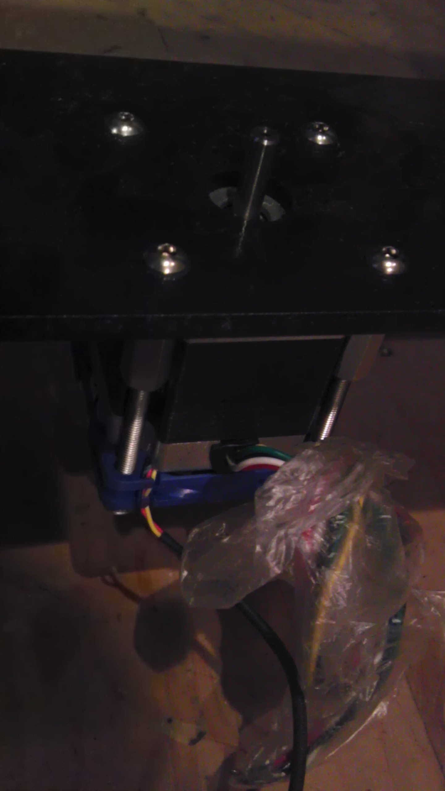
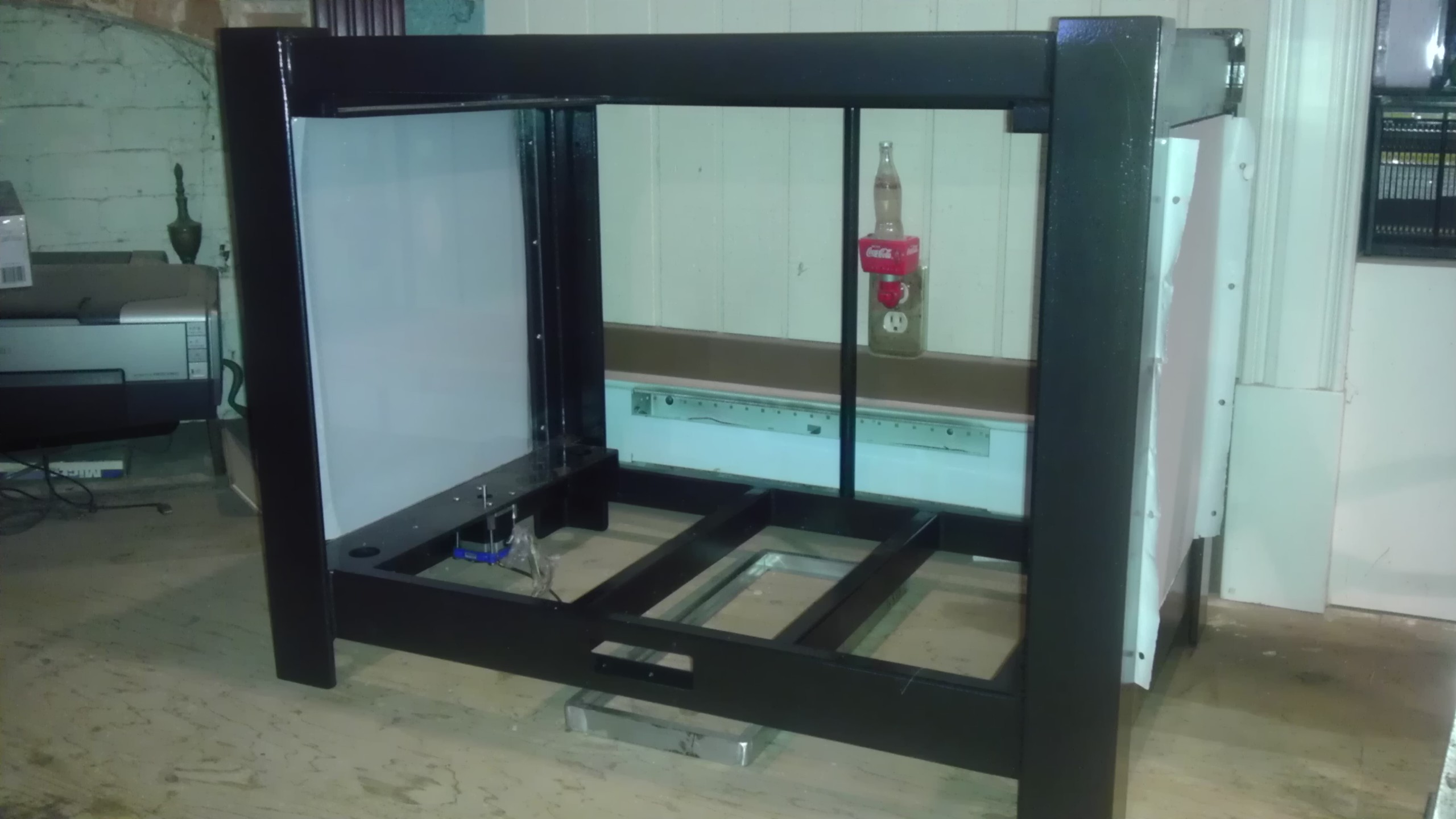
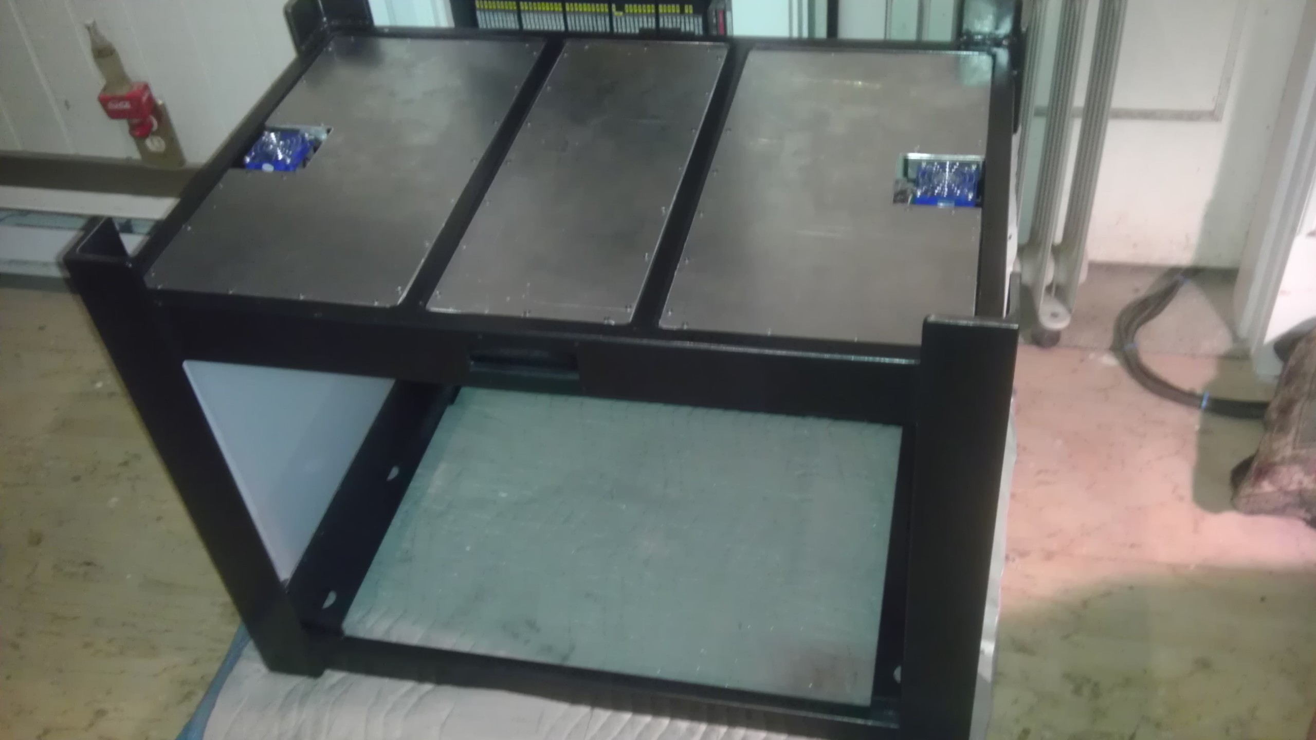
Well, I've finally begun installing the first parts in my printer. The end enclosure panels, which are clear polycarbonate are in, as are the Z motors and their fans. I have also begun fabricating the frames for the electronics chassis, the center one of which is visible on the floor under its spot. Once the basic electronics and PSUs are installed, it's on to the stationary rods and their adjusters. This is the thing I have really been looking forward to, because at this point, I get my desk top back! I also have the stand halfway done, I'm just waiting for some hardware. With luck, by the weekend this thing should be off the floor and starting to look like a printer, though I still have ALL the moving parts to make.
|
Re: Design nearly done - construction started... June 28, 2013 01:13PM |
Registered: 11 years ago Posts: 256 |
The electronics are now partially in (LCD soon) though wiring is being held till later. The PSUs (of which a 3rd will be added if I end up using a low voltage bed heater) will get covers shortly. You see the Ramps assy and the driver for the z axis just behind it. Also shown is a shot of the bottom from yesterday. More soon!
|
Re: Design nearly done - construction started... June 29, 2013 09:24AM |
Registered: 10 years ago Posts: 474 |
|
Re: Design nearly done - construction started... July 01, 2013 11:06AM |
Registered: 11 years ago Posts: 256 |
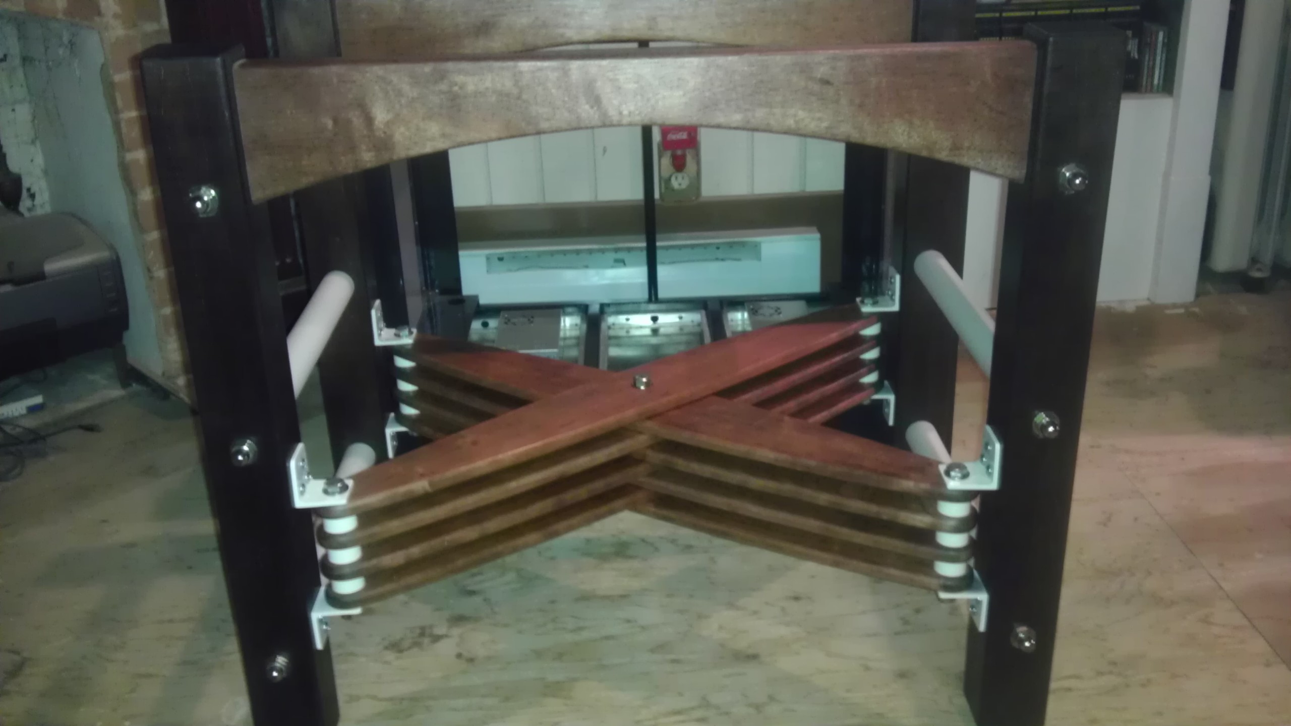
Why thank you, CNC! I know that when I started this thread and this build I swore that I would not use wood anywhere in this printer, however, I said nothing about UNDER the printer. For the past few days, I have been working on the base, in maple, mahogany and cherry. Basically, I'm using up a bunch of stuff I needed rid of anyway, so my only cost is the hardware. (and time) I want to get this guy up off the ground before I add anymore parts, not only is it getting heavier, but harder to grab. So look for this today or tomorrow.... Then the real fun begins.
|
Re: Design nearly done - construction started... July 06, 2013 10:11PM |
Registered: 11 years ago Posts: 256 |
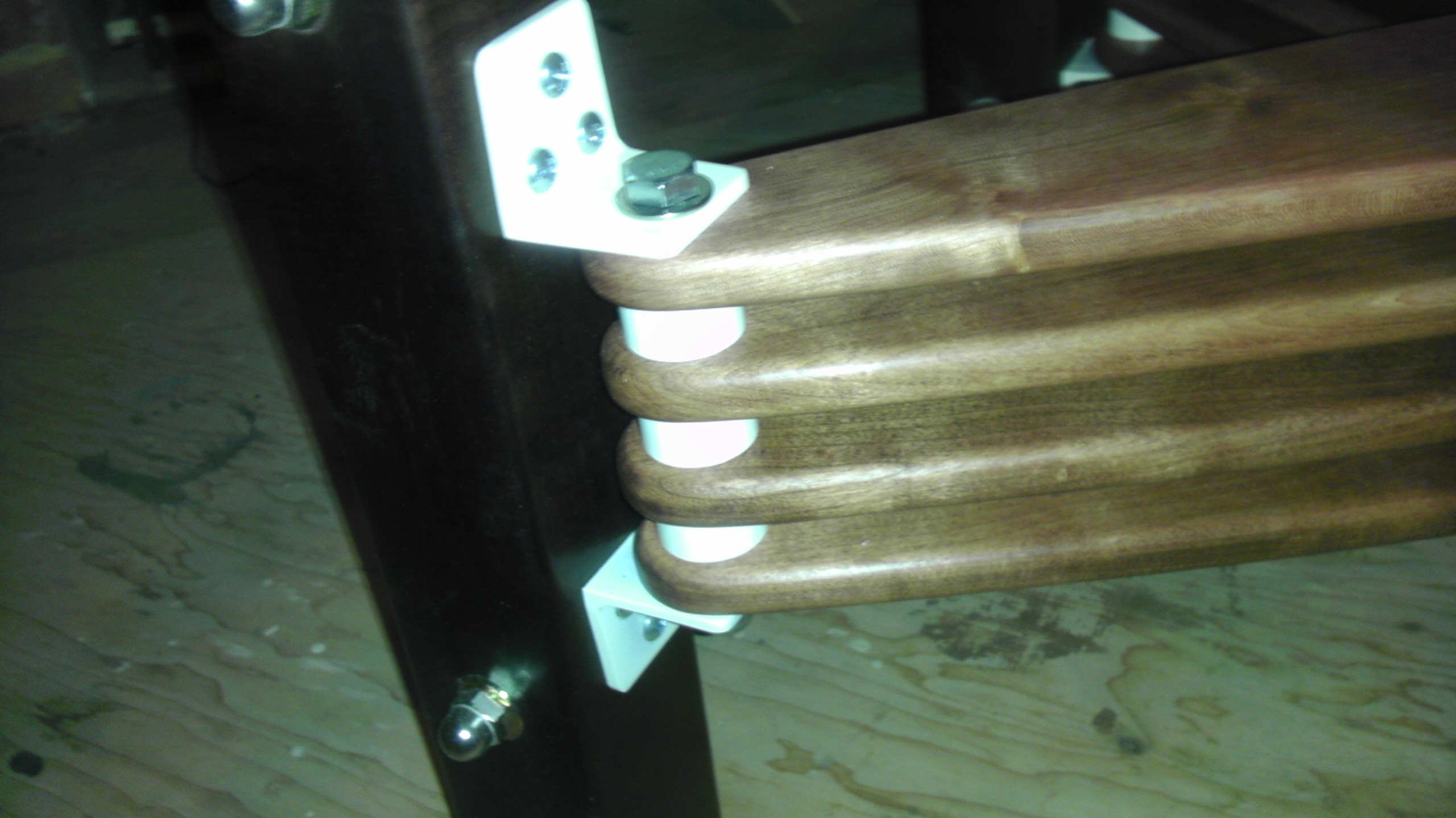
Well, I managed to cobble together a base for my printer from some shop scraps.... I did in fact have all the materials laying around except for the nuts and bolts. The end spreaders are PVC pipe pressed onto steel pipe; the spacers between the spreaders and the angle brackets were machined in steel, and powder coated, in practice for the powder coating I will be doing on some of the printer parts. This seriously falls under the category of "vehicle depicted with optional items"! Now I can get back to work...
I did in fact have all the materials laying around except for the nuts and bolts. The end spreaders are PVC pipe pressed onto steel pipe; the spacers between the spreaders and the angle brackets were machined in steel, and powder coated, in practice for the powder coating I will be doing on some of the printer parts. This seriously falls under the category of "vehicle depicted with optional items"! Now I can get back to work...
|
Re: Design nearly done - construction started... July 07, 2013 01:10PM |
Registered: 17 years ago Posts: 392 |
Very cool, you have a nice sense of design. Love how you reused nice offcuts. 10 on 10.
Yvan
Singularity Machine
Yvan
Singularity Machine
|
Re: Design nearly done - construction started... July 12, 2013 10:52AM |
Registered: 11 years ago Posts: 256 |
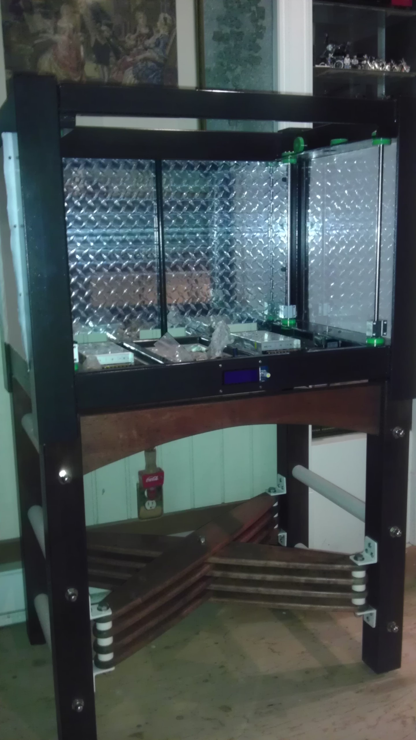
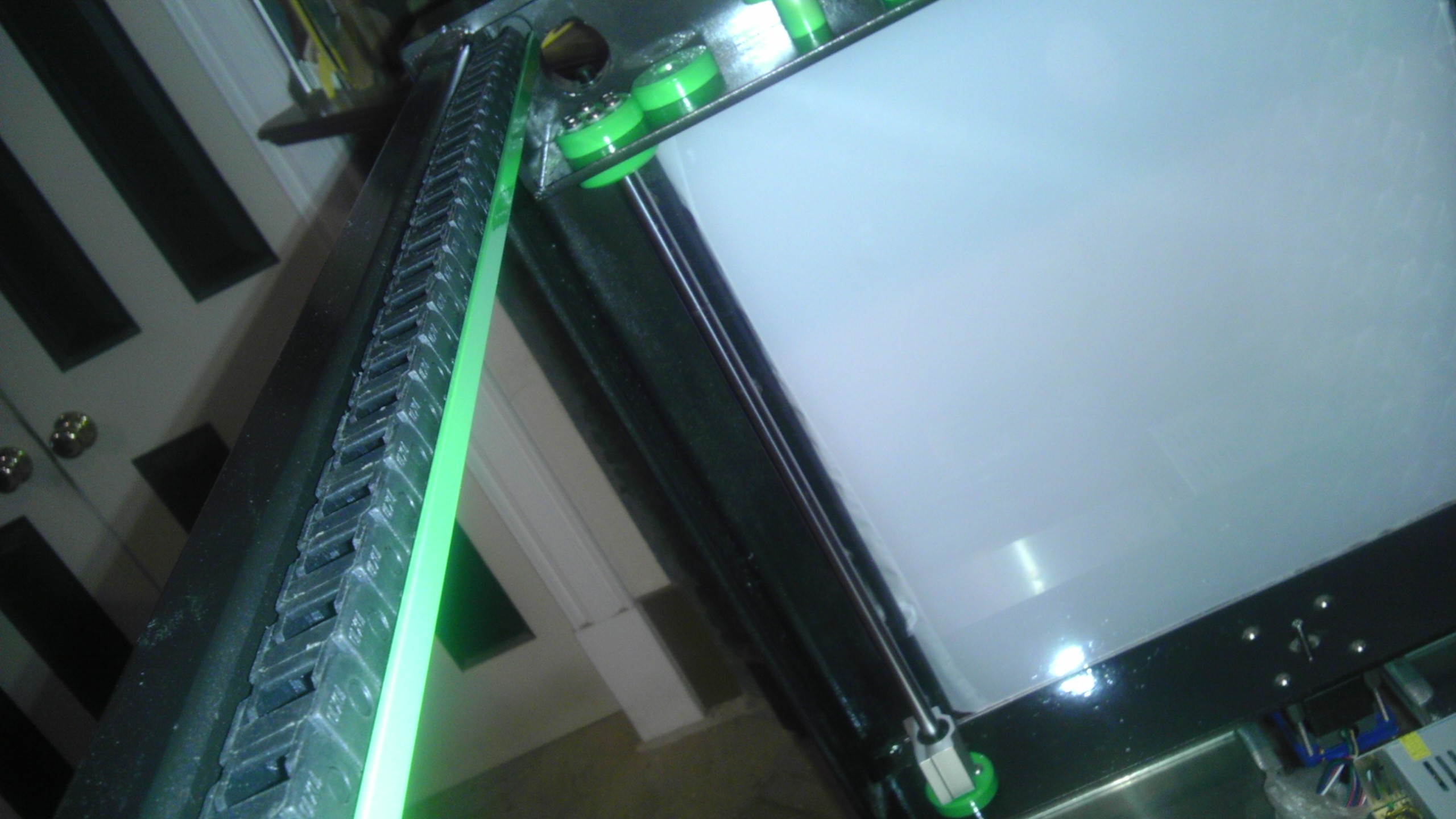
I've installed the printer on its base and begun installing the linear rods and bearings. A couple of quick shots before I begin alignment of the z rods, so that I can then install the Y rods, and Z screws. In other words, my printer is starting to get printer parts in it.> <
<
<
|
Re: Design nearly done - construction started... July 12, 2013 11:55AM |
Registered: 10 years ago Posts: 474 |


Sorry, only registered users may post in this forum.