Design nearly done - construction started...
Posted by Maxx Mayhem
|
Re: Design nearly done - construction started... February 19, 2014 05:23PM |
Registered: 11 years ago Posts: 256 |
If it is the same chip, there could be an issue. The fellow who runs MassMind and I spoke last year when I was building the driver, and he told me that the particular Toshiba chip was a one off, and that he was in the process of developing a new product based on another chip. I had planned to get back to him as soon as I got things running, clearly the time frame has expanded slightly....We will see how things go with pololus on the 17s, because A. I need so many of them, and B. because I need to stuff them into a small space. With the 9 pololus and the one 6064, ( for the 2) 23s)I am hoping things will work the way I want. So far, the only thing I have tested is the 6064, with the 23s and only in a test mode, not with controls. My concept is - with the sheer amount of fabrication involved, even a catastrophic failure at the initial start up of the electronics ( which I doubt, as all turns on and lights light up) would be a small issue. As the extruder assembly nears completion, my prime interest now is finalizing the design of and completing the construction of the carriage, all without losing cubic inches. Your opinion on something please... I know you have a preference for hollow rods, but due to the fact I want to keep my adjuster system intact, I need to use a turned down solid rod. For my long axis I am planning to move to a 25 mm rod from a 12 mm rod. An online calc tells me to expect about 1/8 the flex... Wondering if you have any experience that you could share regarding this...Thanks On another note it seems I have been waiting forever for a barometric pressure gauge from china, I want to pair it with a picoduino and led matrix to make an altimeter for small rockets...
for small rockets...
|
Re: Design nearly done - construction started... February 19, 2014 07:16PM |
Registered: 10 years ago Posts: 474 |
This is a Toshiba chip TB 6600 the one before it was the one that I think had all the troubles as far as the chip goes it seems to have good reviews in fact there's a problem with supply. As far as the mainboard goes it looks good like I say there is a couple of photos of prints at there forum that looks fantastic
Edited 1 time(s). Last edit at 02/19/2014 07:20PM by cnc dick.
Edited 1 time(s). Last edit at 02/19/2014 07:20PM by cnc dick.
|
Re: Design nearly done - construction started... February 19, 2014 07:25PM |
Registered: 10 years ago Posts: 474 |
hollow would be less SAG but if you have to go with solid give it a try it should be rigid but tend to droop just a little in the middle. If you could find the right hollow rod and then just do stub ends that pressed in or threaded would be to best. Like I said in the above post it is TB 6600 which I think is the newer version. Yeah the Chinese new year sets them back a monthQuote
Maxx Mayhem
If it is the same chip, there could be an issue. The fellow who runs MassMind and I spoke last year when I was building the driver, and he told me that the particular Toshiba chip was a one off, and that he was in the process of developing a new product based on another chip. I had planned to get back to him as soon as I got things running, clearly the time frame has expanded slightly....We will see how things go with pololus on the 17s, because A. I need so many of them, and B. because I need to stuff them into a small space. With the 9 pololus and the one 6064, ( for the 2) 23s)I am hoping things will work the way I want. So far, the only thing I have tested is the 6064, with the 23s and only in a test mode, not with controls. My concept is - with the sheer amount of fabrication involved, even a catastrophic failure at the initial start up of the electronics ( which I doubt, as all turns on and lights light up) would be a small issue. As the extruder assembly nears completion, my prime interest now is finalizing the design of and completing the construction of the carriage, all without losing cubic inches. Your opinion on something please... I know you have a preference for hollow rods, but due to the fact I want to keep my adjuster system intact, I need to use a turned down solid rod. For my long axis I am planning to move to a 25 mm rod from a 12 mm rod. An online calc tells me to expect about 1/8 the flex... Wondering if you have any experience that you could share regarding this...Thanks On another note it seems I have been waiting forever for a barometric pressure gauge from china, I want to pair it with a picoduino and led matrix to make an altimeter
Edited 2 time(s). Last edit at 02/19/2014 07:30PM by cnc dick.
|
Re: Design nearly done - construction started... February 19, 2014 08:20PM |
Registered: 11 years ago Posts: 256 |
|
Re: Design nearly done - construction started... February 21, 2014 01:45PM |
Registered: 11 years ago Posts: 256 |
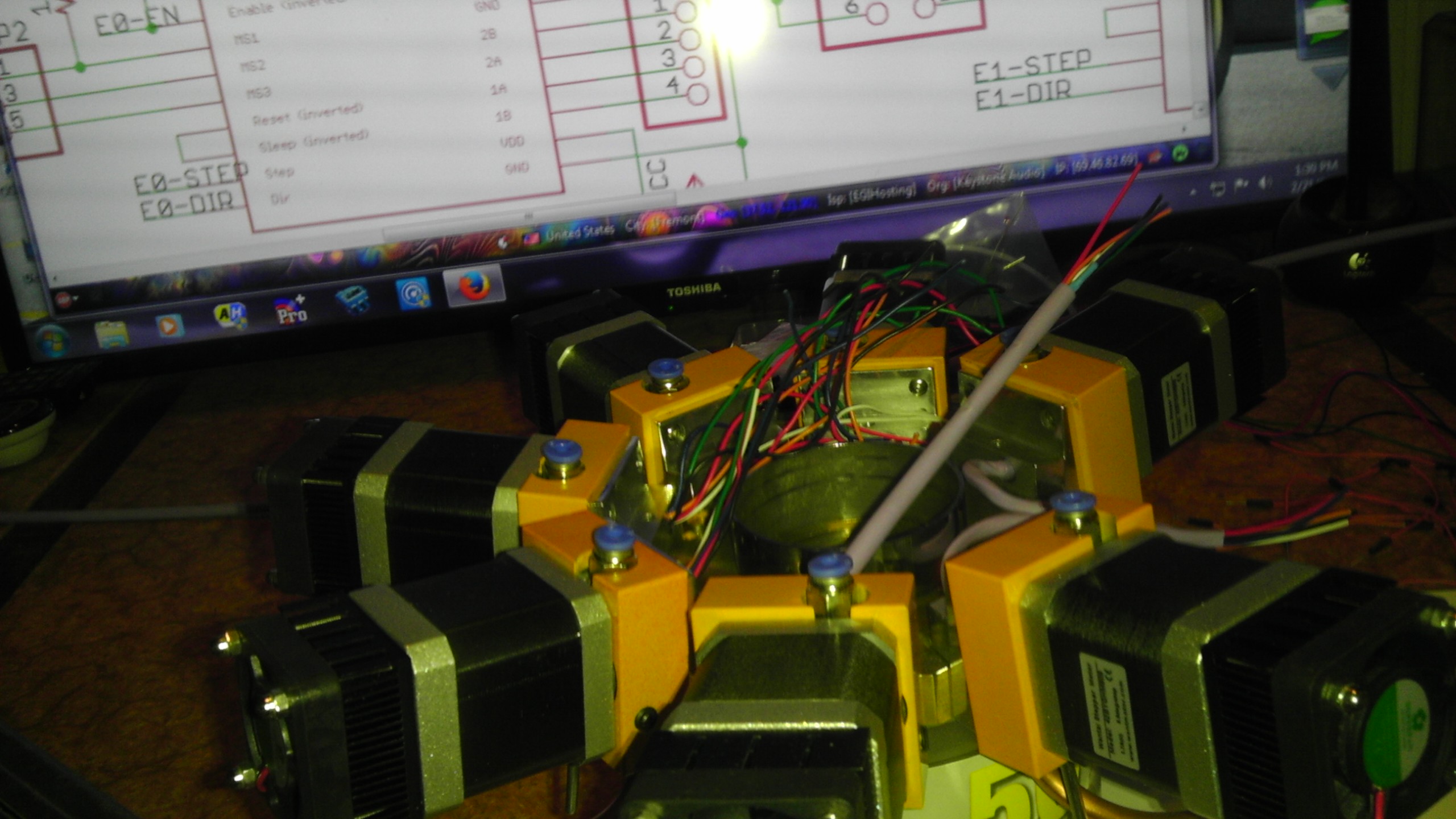
Taking a quick break from soldering... Heres a shot of the extruder assembly from underneath with the bottom cover off. This thing is precisely the diameter of a box of CDs.
 That helps! I'll show you the completed assembly in a few hours.
Heres a shot of the extruder assembly from underneath with the bottom cover off. This thing is precisely the diameter of a box of CDs. That helps! I'll show you the completed assembly in a few hours.
|
Re: Design nearly done - construction started... February 21, 2014 03:20PM |
Registered: 10 years ago Posts: 106 |

|
Re: Design nearly done - construction started... February 21, 2014 06:58PM |
Registered: 11 years ago Posts: 256 |
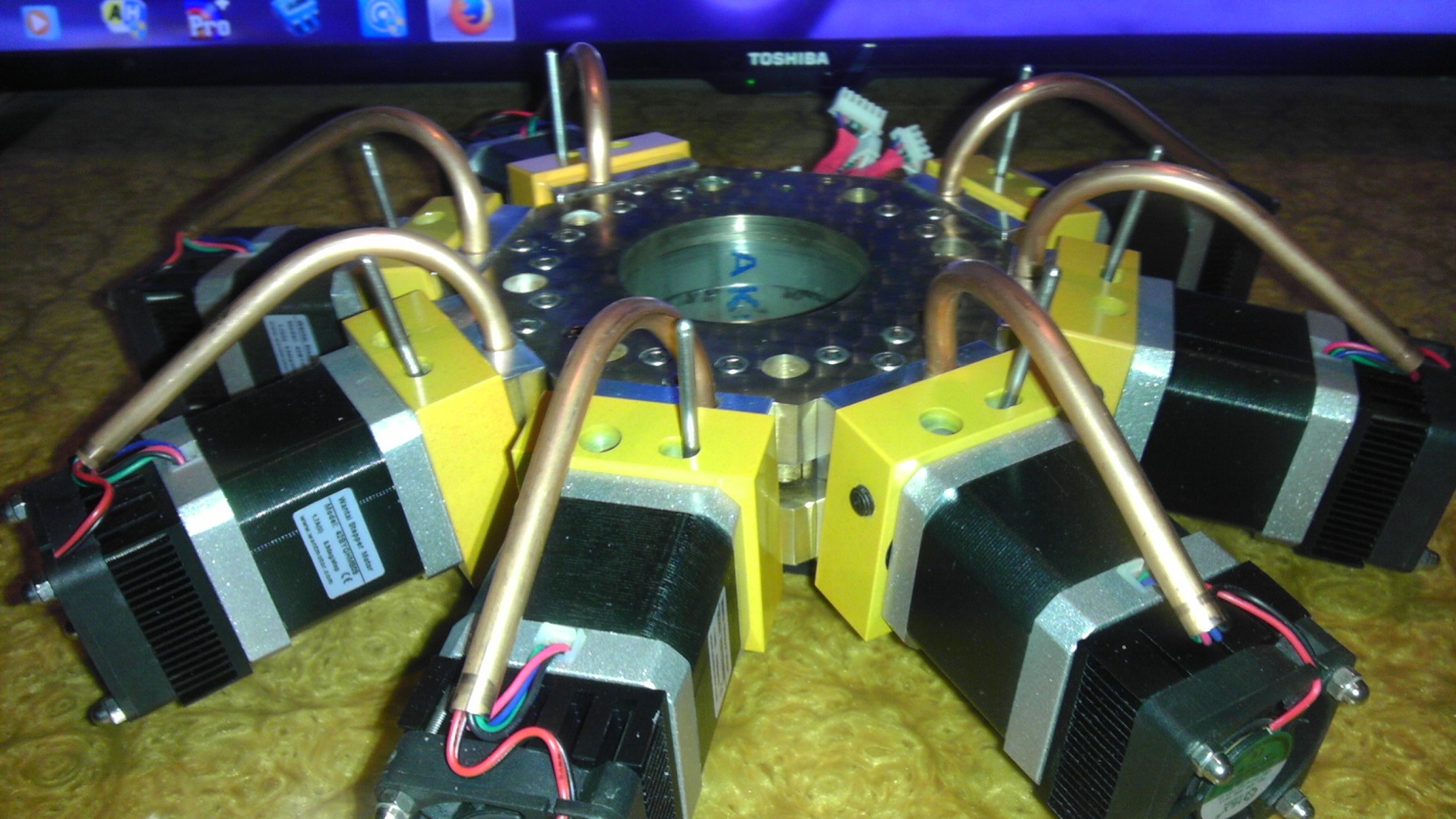
OK so after a good couple of months or so, the cold end assembly is finally DONE!!!!!!!!!!!!
 Next step is the top of the cabinet which will hold this as well as the filament rack. The carriage is also on deck... There is a busload of electronics to do yet, but I have most of the bits and pieces here. More on this story as it develops.
Next step is the top of the cabinet which will hold this as well as the filament rack. The carriage is also on deck... There is a busload of electronics to do yet, but I have most of the bits and pieces here. More on this story as it develops.
|
Re: Design nearly done - construction started... February 21, 2014 08:45PM |
Registered: 10 years ago Posts: 474 |
Looks good Maxx like I say I designed and built machines of my own for a lot of years I know what that takes. I hope you're going to be able to utilize more than two extruders.I don't think slicing software at the moment is capable of more than two maybe three although I'm sure in the future it will be applicable
Edited 2 time(s). Last edit at 02/21/2014 08:54PM by cnc dick.
Edited 2 time(s). Last edit at 02/21/2014 08:54PM by cnc dick.
|
Re: Design nearly done - construction started... February 21, 2014 09:28PM |
Registered: 11 years ago Posts: 256 |
I believe that the slicing software does in fact have support for any number of extruders. The issue is firmware support - to wit I am getting ready to build a RAMPS expander board and write a firmware patch that will make it all work.  Edit-Just checked (and updated) Repetier. Under printer configuration, there is a space for extruders, that seems to allow you to add as many as possible.
Edited 1 time(s). Last edit at 02/21/2014 09:46PM by Maxx Mayhem.
Edit-Just checked (and updated) Repetier. Under printer configuration, there is a space for extruders, that seems to allow you to add as many as possible.Edited 1 time(s). Last edit at 02/21/2014 09:46PM by Maxx Mayhem.
|
Re: Design nearly done - construction started... February 21, 2014 09:41PM |
Registered: 10 years ago Posts: 1,381 |
Quote
Maxx Mayhem
Instead of using drive belts as belts, I will epoxy them to solid channels and use them to make a rack and pinnion drive for the X, Y axis.
In this way, I hope to eliminate slop, stretch, and the inherent backlash from the belts.
Maybe this has been discussed already...?
Belts are designed to operate wrapped around a pulley, and when sized for the job the backlash is not significant.
Laying a belt flat, and using it as a rack with a pulley rolling on top will have some backlash.
A large GT2 belt, or multiples shouldn't have meaningful backlash.
Neat project, I enjoy your pics!
|
Re: Design nearly done - construction started... February 21, 2014 09:51PM |
Registered: 11 years ago Posts: 256 |
Thank you A2, the X axis on my machine is around 28" of travel. My concern with a 5 foot belt is that the weight of it and dynamic forces would tend to create a serious reliability issue with respect to accuracy. I can visualize where you would think that backlash would come in, however I've plans in the works to neutralize that problem... My initial idea was to have a separate rack, but after giving it some thought have decided to machine a slot for the rack gear right into the main transverse rod. This allows me to have fine control of the contact between cog and belt, and guarantees no belt stretching. I'm also working on some addl' details to enhance the contact point.
Edited 1 time(s). Last edit at 02/21/2014 09:59PM by Maxx Mayhem.
Edited 1 time(s). Last edit at 02/21/2014 09:59PM by Maxx Mayhem.
|
Re: Design nearly done - construction started... February 22, 2014 02:43AM |
Registered: 10 years ago Posts: 474 |
hello Maxx I think I would give the belt as a rack some more thought I think he's a right. Plus at best you're only going to have one tooth engaged, unless you have an enormous pinion one tooth of even a good size belt is very flexible. And If you go with a metal one I think it's going to be very noisyQuote
A2
Quote
Maxx Mayhem
Instead of using drive belts as belts, I will epoxy them to solid channels and use them to make a rack and pinnion drive for the X, Y axis.
In this way, I hope to eliminate slop, stretch, and the inherent backlash from the belts.
Maybe this has been discussed already...?
Belts are designed to operate wrapped around a pulley, and when sized for the job the backlash is not significant.
Laying a belt flat, and using it as a rack with a pulley rolling on top will have some backlash.
A large GT2 belt, or multiples shouldn't have meaningful backlash.
Neat project, I enjoy your pics!
|
Re: Design nearly done - construction started... February 22, 2014 04:17AM |
Registered: 10 years ago Posts: 474 |
Maxx I think if I were you and going to go with a traveling motor instead of using the belt has a rack I think I would use a system with the drive pulley on the motor belt looped around it and two smooth idlers on the back of the belt in a U-shaped configuration could be all be done on motor mount mounted to the carriage. That way the belt would only be a little over 30 inches long and fastened to each end of the frame adjustment could be on one end of frame cutting the stretch in half compared to normal configuration
Edited 2 time(s). Last edit at 02/22/2014 04:19AM by cnc dick.
Edited 2 time(s). Last edit at 02/22/2014 04:19AM by cnc dick.
|
Re: Design nearly done - construction started... February 22, 2014 08:03AM |
Registered: 10 years ago Posts: 1,381 |
@cnc dick:
I was thinking the same thing.
ServoBelt
[www.youtube.com]
[www.youtube.com]
Belt-on-Belt drive
3mm HTD belts
[www.youtube.com]
Tractoring
timing belt tractoring, 'XL' belting sourced from McMaster Carr
[www.youtube.com]
I was thinking the same thing.
ServoBelt
[www.youtube.com]
[www.youtube.com]
Belt-on-Belt drive
3mm HTD belts
[www.youtube.com]
Tractoring
timing belt tractoring, 'XL' belting sourced from McMaster Carr
[www.youtube.com]
|
Re: Design nearly done - construction started... February 22, 2014 12:41PM |
Registered: 11 years ago Posts: 256 |
CNCD,I think that you are picturing a stretched belt, I had a different design in mind...
Thank you A2, I kind of like the belt on belt concept , but for the time being the design I have for the rack portion goes as follows; I'll have a 25mm linear rod, turned down at the ends to work with my existing adjustment system, slotted along its length to accommodate a section of GT2 belt, which will be epoxied in place, the face of the belt flush to the surface of the rod. A high quality set of pulleys will be modified to accommodate the necessary cross section that creates. The motor carrier plate will float in the carriage, and be sprung to maintain the correct pressure to minimize wear on the belt, and avoid slippage. A simple V block used to aid in setup to machine the slot can be called back into use to re mill the slot clean, if and when the belt wears. 25 mm linear bearings are 6 row. There is sufficient space between rows to clear the width of a GT2 belt, and the bearings will be fixed relative to their radial position to accommodate this. I know that this may come as a shock, but there are (admittedly few) times I like to find the simplest solution, and this is one of them. But to address the idea of stretching, I am considering putting the long axis rods into tension on the frame of the machine, as that frame will certainly allow for this, which should eliminate any rod flexing, though it may require dampening. In designing a piece of machinery, I feel that I share in Adrien's philosophy as far as trying to make machines more like us. So it helps to separate the components into core, connecting and distal parts, like the human body. I don't want to write a book (today) but I will say that I like to look at each element of the machine and try to figure out whether it needs to be simple, or whether it needs to be adjustable, whether it needs to be immovable, or reparable. Being able to adjust, to repair, to modify many parts will be necessary. It is my hope that this will not apply to the basic frame as a component, though as a sub-assembly, it is loaded with adjustability. But the carriage has to be light. Formula 1 light. $20,000 bicycle light... That's why its design and construction has been held to last. I may well chuck a number of bits before I am happy with it. But let's keep in mind - 50 microns, 3+ cubic feet. So speed is everything. I can visualize the carriage I would make if I had a SLS machine, So we'll see if I can get close with the Harbor freight and a dremel tool, or if I have to suck it up and commission Shapeways to do it.
Thank you A2, I kind of like the belt on belt concept , but for the time being the design I have for the rack portion goes as follows; I'll have a 25mm linear rod, turned down at the ends to work with my existing adjustment system, slotted along its length to accommodate a section of GT2 belt, which will be epoxied in place, the face of the belt flush to the surface of the rod. A high quality set of pulleys will be modified to accommodate the necessary cross section that creates. The motor carrier plate will float in the carriage, and be sprung to maintain the correct pressure to minimize wear on the belt, and avoid slippage. A simple V block used to aid in setup to machine the slot can be called back into use to re mill the slot clean, if and when the belt wears. 25 mm linear bearings are 6 row. There is sufficient space between rows to clear the width of a GT2 belt, and the bearings will be fixed relative to their radial position to accommodate this. I know that this may come as a shock, but there are (admittedly few) times I like to find the simplest solution, and this is one of them. But to address the idea of stretching, I am considering putting the long axis rods into tension on the frame of the machine, as that frame will certainly allow for this, which should eliminate any rod flexing, though it may require dampening. In designing a piece of machinery, I feel that I share in Adrien's philosophy as far as trying to make machines more like us. So it helps to separate the components into core, connecting and distal parts, like the human body. I don't want to write a book (today) but I will say that I like to look at each element of the machine and try to figure out whether it needs to be simple, or whether it needs to be adjustable, whether it needs to be immovable, or reparable. Being able to adjust, to repair, to modify many parts will be necessary. It is my hope that this will not apply to the basic frame as a component, though as a sub-assembly, it is loaded with adjustability. But the carriage has to be light. Formula 1 light. $20,000 bicycle light... That's why its design and construction has been held to last. I may well chuck a number of bits before I am happy with it. But let's keep in mind - 50 microns, 3+ cubic feet. So speed is everything. I can visualize the carriage I would make if I had a SLS machine, So we'll see if I can get close with the Harbor freight and a dremel tool, or if I have to suck it up and commission Shapeways to do it.
|
Re: Design nearly done - construction started... February 22, 2014 01:21PM |
Registered: 10 years ago Posts: 474 |
|
Re: Design nearly done - construction started... February 22, 2014 05:14PM |
Registered: 11 years ago Posts: 256 |
|
Re: Design nearly done - construction started... March 01, 2014 11:41AM |
Registered: 11 years ago Posts: 256 |
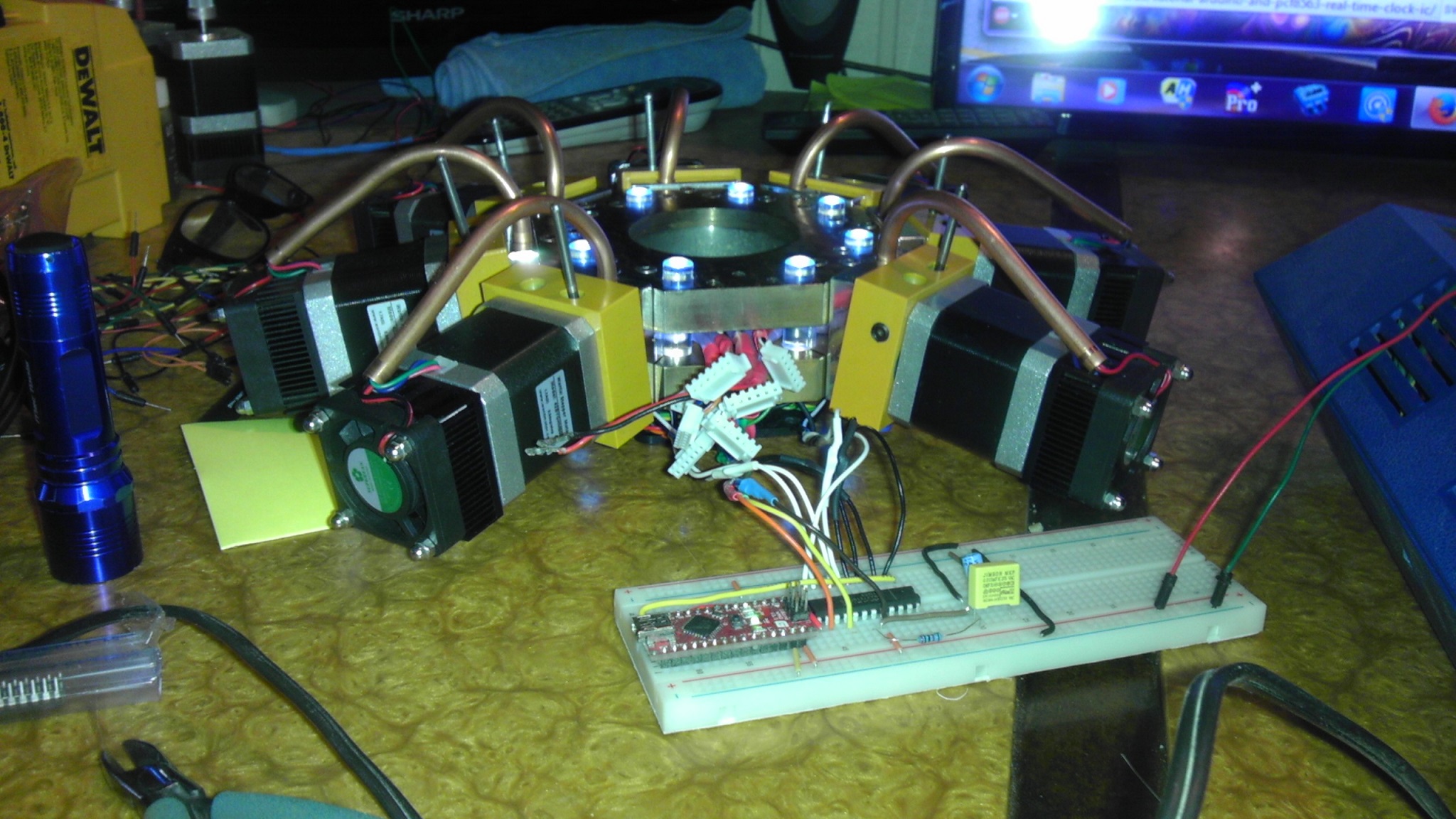
This week I am waiting to get my 25mm rod from Misumi, so that I can beef up my long axis. I have a tracking number, so it should not be long. Also, I should have a price on my heater on Monday. I found a place more willing to do single pieces, and does not charge a setup fee. I'll keep you posted on how this turns out. I had noticed that one of our reputable vendors has heat pads that would divide evenly into my build stage size, but I would need 6 of them and at least 3 more power supplies, control would have been complicated. Obviously, a single mains driven heater is the only way to go at this size. In the interim, I took a couple of evenings to do a little lighting on the extruder assembly. What started as hold down holes for the rough milling on the rotary table became an opportunity to engage in silly arduino tricks. Ultimately, I will write some much more robust code, that will not only make a better light show, but will also provide operational feedback.I will incorporate at least 1 or 2 additional arduinos beyond the primary Mega, to run lights, digital readouts, cooling, and whatever else I come up with. I plan to start on the top assembly tis weekend, which will be made from wood, metal and polycarbonate. There is a circuitry housing unit, cooling system for the hotend, and additional interior lighting going into the top, which will open for access to the mechanicals.
|
Re: Design nearly done - construction started... March 04, 2014 12:06PM |
Registered: 11 years ago Posts: 256 |
CNCD, you had asked how I was going to address more than 2 extruders in repetier... The hardware answer involves physically multiplexing the pins related to the extruders, and the firmware answer resides in pins.h. You need to declare your additional pins here, then add the extruders in configuration.h. Then you need only your models. I am most familiar with Autocad, versus other modelers. In autocad, I would create the model, putting each material as a layer, make each layer a block, export each block and create an stl. Then just register them on the plate, an cross your fingers...
|
Re: Design nearly done - construction started... March 04, 2014 12:22PM |
Registered: 10 years ago Posts: 474 |
Hello Maxx it sounds pretty good the only problem I could see if you use multiple colors on the same layer. You would have definitely have to use the z lift or Z hop in whatever slicer you use with each individual STL that was larger than your layer height so that the nozzle didn't clip the the part of the print that was already done if you have to pass over it. And obviously piece all the G code together
Edited 1 time(s). Last edit at 03/04/2014 12:27PM by cnc dick.
Edited 1 time(s). Last edit at 03/04/2014 12:27PM by cnc dick.
|
Re: Design nearly done - construction started... March 04, 2014 02:42PM |
Registered: 11 years ago Posts: 256 |
As I understand the process (as if I totally did ), the colors go down as they come up in the print, so for example, if you were printing a checkerboard, you would continually alternate the colors as you move from square to square, using your offset parameter to hop the carriage between colors. This is not without its challenges, of course, as getting right or not makes all the difference in the ability to have a crisp delineation between colors. Take a more difficult example, such as a mag wheel with a tire mounted. Here you have the transition between the rim, and the tire bead which must be not only perfectly crisp, but perfectly round as well. Added to that you want a softer plastic for your tires, especially if you are making say, an RC car...
Basically, all the extruders must work together in turn to produce the part, the only way you could do a whole color at a time would be with a free 5 axis approach. I have considered this as a future add-on, done right it could be excellent for details such as rivets, etc...
As for the g-code, how this works, is actually a bit easier than it sounds. As I mentioned, you are taking a single .dwg and making all of the bits at one time. What you have to do is first, make sure all of the parts are legitimate solids, second that these solids do not overlap, and third that there are no inappropriate voids between parts. This can generally be done simply using snaps to align parts. As you work, it is a good idea to keep in mind the final color / material of each part of your model. The parts of your model should be layered at one final output color per layer, colors bylayer should be selected while drawing. It is important to note that the layers in Autocad are not necessarily stratified, like a pack of American cheese, but can interlock, like a wood block puzzle. A block in Autocad is basically a part, or group of parts of a given size, and relative position. So if you drew up a sofa and love seat, 10 inches and 90 degrees apart and made a block, every time you import this block into your drawing, they would be the same size, and the same distance apart. So by taking each layer of your drawing, and making a block of it, you now have the sets of objects that will be nested together. Your slicing software can handle this no problem. Just open your first file, and import the next 6 (or something like that) and then it is just a matter of dragging all the parts into their final, nested position. No different than registering the colors on a 2 dimensional offset print, except you have 3 dimensions. Of course, the fewer uncontrolled variables you have to work against, the more possible the math becomes. Very solid machines ultimately lay the ground work for the positioning repeatability and accuracy that allows for greater control over the ability to line up these multiple colors and materials. Naturally, I expect to spend several days making spaghetti in one color, before even thinking about waking up in the morning to a 1:6 Mercury capsule, but I do believe the bits are all there to make this work. The hardware is the most labor intensive to be sure, the simplicity of the software is the thing that makes this all scalable. As a side note, I have as yet not spent sufficient time with the free cad products out there to really have a thorough understanding of how to get around on them, so some of the above may not apply to what a lot of us are using.
), the colors go down as they come up in the print, so for example, if you were printing a checkerboard, you would continually alternate the colors as you move from square to square, using your offset parameter to hop the carriage between colors. This is not without its challenges, of course, as getting right or not makes all the difference in the ability to have a crisp delineation between colors. Take a more difficult example, such as a mag wheel with a tire mounted. Here you have the transition between the rim, and the tire bead which must be not only perfectly crisp, but perfectly round as well. Added to that you want a softer plastic for your tires, especially if you are making say, an RC car... Basically, all the extruders must work together in turn to produce the part, the only way you could do a whole color at a time would be with a free 5 axis approach. I have considered this as a future add-on, done right it could be excellent for details such as rivets, etc...
As for the g-code, how this works, is actually a bit easier than it sounds. As I mentioned, you are taking a single .dwg and making all of the bits at one time. What you have to do is first, make sure all of the parts are legitimate solids, second that these solids do not overlap, and third that there are no inappropriate voids between parts. This can generally be done simply using snaps to align parts. As you work, it is a good idea to keep in mind the final color / material of each part of your model. The parts of your model should be layered at one final output color per layer, colors bylayer should be selected while drawing. It is important to note that the layers in Autocad are not necessarily stratified, like a pack of American cheese, but can interlock, like a wood block puzzle. A block in Autocad is basically a part, or group of parts of a given size, and relative position. So if you drew up a sofa and love seat, 10 inches and 90 degrees apart and made a block, every time you import this block into your drawing, they would be the same size, and the same distance apart. So by taking each layer of your drawing, and making a block of it, you now have the sets of objects that will be nested together. Your slicing software can handle this no problem. Just open your first file, and import the next 6 (or something like that) and then it is just a matter of dragging all the parts into their final, nested position. No different than registering the colors on a 2 dimensional offset print, except you have 3 dimensions. Of course, the fewer uncontrolled variables you have to work against, the more possible the math becomes. Very solid machines ultimately lay the ground work for the positioning repeatability and accuracy that allows for greater control over the ability to line up these multiple colors and materials. Naturally, I expect to spend several days making spaghetti in one color, before even thinking about waking up in the morning to a 1:6 Mercury capsule, but I do believe the bits are all there to make this work. The hardware is the most labor intensive to be sure, the simplicity of the software is the thing that makes this all scalable. As a side note, I have as yet not spent sufficient time with the free cad products out there to really have a thorough understanding of how to get around on them, so some of the above may not apply to what a lot of us are using.
|
Re: Design nearly done - construction started... March 04, 2014 03:58PM |
Registered: 10 years ago Posts: 474 |
Maxx I really don't understand what you're doing I haven't used AutoCAD in many a year I think it was version 12 an old 2-D version. But I know what you're saying is you can take a block out of AUTOCAD as an STL send it to a slicer have a broken up into layers and from that get G code okay I got that .Now you want two more blocks two more colors same height. In other words multiple colors per layer your sets of G code would do each block and then go on to the next that would would not work. If you make blocks in vertically separations one color per block obviously no problem there it's just one set of G code after another. The Thing is like you said you can't print taller than one or maybe two layer thicknesses because of the diameter of the hot end and nozzle you can't get up next to the printed block you've already laid down unless it's just one layer thickness that would be multiple colors per layer. So it would be a nightmare to do multiple colors per layer. Unless AutoCAD can somehow then take the G code in remake the block in slices. Okay the more I think of it I think I know what your saying is to put them in to your slicer as separate parts on the same platform but have no separation so that they we will be bonded and then slice. The only thing is I don't know if that can be done if you put multiple parts into the slicers that I have used it wants to give you a spacing in between the parts. But even then it would treat them as one and you wouldn't be able to assign colors or extruder number per block
Edited 3 time(s). Last edit at 03/04/2014 04:29PM by cnc dick.
Edited 3 time(s). Last edit at 03/04/2014 04:29PM by cnc dick.
|
Re: Design nearly done - construction started... March 04, 2014 04:30PM |
Registered: 11 years ago Posts: 256 |
The slicer actually takes care of this. Actually, I have really old autocad myself, same as what you used... The full blown Autocad is 3d, Autocad lte is 2d, they have an affordable cloud product now. Anyway, you have the word layer used differently in different places. Obviously, layers on your printer are flat things that stack like pancakes. In Autocad, in a 3d environment, layers do not have a vertical hierarchy, as they might in CorelDRAW, for example. They are basically groups of objects, like a group in Corel. So, these layers in Autocad can exist through other layers. Think of designing a house... You have walls on one layer, pipes on another layer, windows on yet another . So when you get your house built, the pipes are not above the house, they are in the house. This is how layers relate in Autocad. When the printer prints, it does not print one color at a time. As the print head passes over the work,the slicer activates the appropriate hotend for the color needed at any point in the work. So how does this work. The answer is as simple as it is complicated. The slicer can only print models in a single color. It can however print numerous models in the same space, each their own single color. And all at the same time It neither knows nor cares that it is doing this. So each color is actually a separate model, and they are printed at basically the same origin point. Well not exactly, they are in fact offset in origin, but if you properly overlap them in all 3 dimensions, and don't actually have mass sharing the same space, it can print a perfect multi color object, if all goes well. So in a sense, you are printing a bunch of models inside each other, with each color being a model. The trick is to open your first model and import the rest, and then the slicer knows what to do with them. So the print head is very busy changing colors all through the single layer, and layers are still built up the same way as they would be in one color - front to back, left to right, at a single height.
|
Re: Design nearly done - construction started... March 04, 2014 04:44PM |
Registered: 10 years ago Posts: 474 |
Okay Maxx so you put multiple STL's on the same platform and somehow get them precisely lined up. And then assign different extruders for different STL's and then slice the package. I don't think the slicers I've used will let you do that but I haven't tried any new slicers in a year
Edited 1 time(s). Last edit at 03/04/2014 04:46PM by cnc dick.
Edited 1 time(s). Last edit at 03/04/2014 04:46PM by cnc dick.
|
Re: Design nearly done - construction started... March 04, 2014 06:15PM |
Registered: 11 years ago Posts: 256 |
The last one I saw (open source) it was all in the manner in which you open the files. I will try and find the vid if I can. The Makerbot software has a more user friendly appproach, but it is for the Makerbot and it is for two colors as the makerbot only has two colors...
This just in!
What you evidently want is the new slic3r RC3. This has support for multiple extruders. I found it just now while trying to find something I saw several months ago...I will be tying this into repetier, and I think this will complete the tool chain. If I get a chance later this week, I'll get some files and see how it works.
|
Re: Design nearly done - construction started... March 12, 2014 06:48AM |
Registered: 10 years ago Posts: 474 |
|
Re: Design nearly done - construction started... March 12, 2014 01:38PM |
Registered: 11 years ago Posts: 256 |
Parts are coming in... I got my PID controller with the ramp and soak feature to run the heated bed. Ramp and soak is basically a means to manually pre program the heat curve on the bed. It offloads the work from the ramps board, while I'll still be able to report the bed temp to ramps. This is another thing to have to calibrate, but you do get more temp control of the bed than you will ever get from ramps, along with zero exposure of current from the heater to your control board. I also got a SSR to actually run the heat bed. I'm working on the top of the enclosure which will have a wood frame with aluminum and polycarbonate components. The inside will be heat shielded with an automotive product. The silicon heat blanket is currently in production. I still need to order glass and a silicone sheet for insulation, the 25mm linear bearings are making their leisurely way across the pacific, so the carriage is still on hold. I do plan to get a lot done this weekend, the last several days were spent giving my truck a 1/4 million mile tuneup. I have a couple of lighting details to put together, they take the least time and cost by far the least money, but I don't want to do everything twice. I am still batting a few different ideas about for the multi hotend head. One thing's for certain, it will be an interchangeable part so I can try a few things. One hotend is out of the question, due to concerns with contamination and the fact that I will be printing in up to not only 7 colors, but 7 materials as well. If you go the restaurant and get soda, usually it tastes wrong because all of the flavors pass thru the same nozzle. So think of how much more viscous filament is than a beverage. Right now, I'm looking at extraction as the best path to take.
I hope to have a few pics in the next few days.
I hope to have a few pics in the next few days.
|
Re: Design nearly done - construction started... March 23, 2014 07:53PM |
Registered: 11 years ago Posts: 256 |
Quickly, this weekend, I have been working on a couple of parts for the printer. One is the top frame which will hold the extruders, the cooling system and roughly half of the electronics...It is made from wood, being the easiest way to get the shape I wanted, and is halfway thru finishing right now. I know I said at the outset I was staying away from wood for this build, but it is not a piece which effects the geometry, so...Second, I am machining the primary linear rod that I will use for the long axis. This includes sizing to length, turning down and tapping the ends and milling a slot for the belt which will form the integral rack and pinion drive. This will be the most difficult part, as the rod is hardened, and I bought only one end mill, so I guess I'll be using lots and lots of oil... Pix next week.
|
Re: Design nearly done - construction started... March 26, 2014 02:12PM |
Registered: 11 years ago Posts: 256 |
I've been on the phone ALL day to try to find a machine shop to slot my linear rods. There are a few specific issues such as capacity (length ) of their machinery, cutter availability, and how stiff the machine is. A bridgeport won't do the trick, you need a big, heavy machining center. So the harbor freight mill is out of the question. Rockwell 61 surfaces tend to chip carbide tooling, so there is that. One thing's for certain, this is not happening today. 2 weeks seems to be the common backlog, and being a contractor, I know precisely what that means. I once left a piece of plating for 2 weeks, and picked it up 13 months later... Nor will it be cheap - the minimum cost to do this would buy a bottom of the line printer kit. But, this must be done. In the meantime, there are a few more items I can do before I get down to the final item - the carriage assembly, and you will be seeing those thing as they get done.
Rockwell 61 surfaces tend to chip carbide tooling, so there is that. One thing's for certain, this is not happening today. 2 weeks seems to be the common backlog, and being a contractor, I know precisely what that means. I once left a piece of plating for 2 weeks, and picked it up 13 months later... Nor will it be cheap - the minimum cost to do this would buy a bottom of the line printer kit. But, this must be done. In the meantime, there are a few more items I can do before I get down to the final item - the carriage assembly, and you will be seeing those thing as they get done.
|
Re: Design nearly done - construction started... March 26, 2014 02:33PM |
Registered: 10 years ago Posts: 1,381 |
I'm curious, can you post a pic of what you're trying to machine, the type of steel, and it's heat treat process.
If it's long use a boring mill, I used to operate one, you could easily put a car on the table.
If it's case harden it's going to warp a lot, and if it's through harden it's still going to warp but not as much.
After machining it will most likely will need to be pressed straight.
EDM machining would be interesting to use, you wouldn't have to worry about moving the clamps as the cutter passed by, but $$$.


Sorry, only registered users may post in this forum.