Design nearly done - construction started...
Posted by Maxx Mayhem
|
Re: Design nearly done - construction started... April 26, 2013 11:44PM |
Registered: 11 years ago Posts: 256 |
The metal panels are not there for triangulation, they are for the electronics deck. They are aluminum, the bottom pieces are 16 gauge and they need to be dynomatted. The triangulation is achieved thru the Z axis shelves, and the way in which the columns are welded to the upper and lower subframes. Though these pieces are not in and of themselves triangular, they in fact provide the same structural function. My father and I in fact had this same discussion. He designed something that wound up vibrating, as it was riding around on the back of a tank. I'm thinking more of a stationary setup for mine. as for the suspension, think about the way the moving bits are held in place in a complicated watch, like a pin inside of a cone. Only my pin and cone are 12 mm instead of 1/4 mm. Smaller surface area = higher frequency passed. This should control vibration while allowing for more accurate adjustment. As to the wires on the carriage, 2 fans and 7 hotends ala carte is 32 wires. nearly half are carrying power for heating. So I want to mitigate this. If I go digital, I think it would take as few as 3 to 5 wires, that I can live with. I like the suggestion of the granite powder and epoxy- I think I will look into that.
|
Re: Design nearly done - construction started... April 27, 2013 09:54PM |
Registered: 10 years ago Posts: 24 |
|
Re: Design nearly done - construction started... April 27, 2013 10:21PM |
Registered: 17 years ago Posts: 392 |
I didn't know about the surface area/frequency thing. Interesting!
How many hot ends will you need to run at once? All seven for colour blending, or just one at a time? If seven, that means one massive fat high amperage wire pair...
BTW, have you looked into some kind of gimbaled mount for the bowden extruders? If they can swivel around as the X carriage moves around under them, that could help with the flexing/straightening of the bowden shell and filament.
|
Re: Design nearly done - construction started... April 28, 2013 11:05AM |
Registered: 11 years ago Posts: 256 |
This is set to run one color at a time, as it is not practical to blend colors inside the extruder. Even if you could, you end up with a lot of waste, but the complexities of a blending system allow for little speed due to weight alone. Each extruder will be selected one at a time, on demand. In talking with graphic designers, it would seem that for graphic work (as opposed to photographic) they tend to work from a very constrained color palatte. Most logos are 2 or 3 colors. Many products are designed respecting the corporate palatte. A car model for example can be printed in 7 colors -body, interior,black, silver, clear, trans red, trans amber. Most military models can be printed with 7 colors as well. Same with aerospace, scifi, architecture etc. Now properly designed, a bowden tube is its own gimbal. The important design elements are overall length, resting angles, extreme angles etc. The placement of the extruder motors is a key consideration.
I build a lot of different things. So I built this guitar - a Stratocaster with a modified Fender neck and a body made of the same mix of woods in a Les Paul but in the shape of a Stratocaster. In researching this project, I came to find that there was a direct relationship between the critical hardware (nut, bridge / components) and their attachment, and the band of frequencies passed to the body of the instrument and hence reinforced harmonically to be collected by the pickups. So as a partial solution to issues with the tendency of steel to vibrate, I am looking to use the same principles for the attachment of the rods, in addition to damping.
The fun (and by fun I mean the most frustrating) part will be to design the electronics. As I understand the slicer to operate, it seems that as you define additional extruders, it dimensions the array that defines the number of extruders and can pass the associated commands on to either logical or physical extruders. So I would (not having studied it yet) presume that you can patch the firmware to allow for logical addressing on a fixed set of pins (eg those which comprise extruder1) and set instructions to the "logical" (physical extruders 1-6) and make the lot work. So you have one board with 7 pololus that run directly to a multiplexer shield plugged into extruder0 on the ramps, and another multiplexer onboard the carriage which assigns power and returns thermistor readings, plugged into the appropriate one set of holes in the ramps. So if it all works, you have 5 wires to the carriage, the motors are fixed so they have 23 wires I believe,and all should be right with the world. BTW I am running .35 mm Jhead MKV-b (hotends.com) and 1.75 filiment.
I build a lot of different things. So I built this guitar - a Stratocaster with a modified Fender neck and a body made of the same mix of woods in a Les Paul but in the shape of a Stratocaster. In researching this project, I came to find that there was a direct relationship between the critical hardware (nut, bridge / components) and their attachment, and the band of frequencies passed to the body of the instrument and hence reinforced harmonically to be collected by the pickups. So as a partial solution to issues with the tendency of steel to vibrate, I am looking to use the same principles for the attachment of the rods, in addition to damping.
The fun (and by fun I mean the most frustrating) part will be to design the electronics. As I understand the slicer to operate, it seems that as you define additional extruders, it dimensions the array that defines the number of extruders and can pass the associated commands on to either logical or physical extruders. So I would (not having studied it yet) presume that you can patch the firmware to allow for logical addressing on a fixed set of pins (eg those which comprise extruder1) and set instructions to the "logical" (physical extruders 1-6) and make the lot work. So you have one board with 7 pololus that run directly to a multiplexer shield plugged into extruder0 on the ramps, and another multiplexer onboard the carriage which assigns power and returns thermistor readings, plugged into the appropriate one set of holes in the ramps. So if it all works, you have 5 wires to the carriage, the motors are fixed so they have 23 wires I believe,and all should be right with the world.
BTW I am running .35 mm Jhead MKV-b (hotends.com) and 1.75 filiment.
|
Re: Design nearly done - construction started... April 28, 2013 11:59PM |
Registered: 17 years ago Posts: 392 |
Yes, you are right about the restricted palette for logos and such. I'm finding that getting a hold of filament in the exact colour needed is an issue. The range is limited. I'm waiting for a simple ultrasonic agitator for melt chamber colour blending! Or maybe an electromagnetic agitator....
Is automotive and military modeling one of your main 3D printing goals?
I guess one issue with the multiple melt chambers is that each one has to be able to heat up ahead of time while the main colour is being printed. Otherwise there is a wait time when switching from one colour to the next. Pushing each colour into one single melt chamber is one approach, but it has other issues I suppose!
|
Re: Design nearly done - construction started... April 29, 2013 11:57AM |
Registered: 11 years ago Posts: 256 |
Model making is just one of many objectives I have for this machine. I'm also thinking prototypes, custom products, musical instruments, art etc. I too had considered using a single hot end but it adds complexity, as well as asking the one hot end to endure extreme duty cycles. I did have a couple of different methods in mind but at the moment, I am leaning heavily to 7 sets of extruders.
|
Re: Design nearly done - construction started... May 01, 2013 08:28PM |
Registered: 11 years ago Posts: 256 |
I got my 6064 driver kit from Massmind and have it mostly assembled. It was reasonably easy but if you build this kit, be sure and read the instructions that come with it, because the builder is updating these kits regularly as he discovers ways to improve it. Before I assemble the IC, I need to run a couple of tests, which I will do this week as soon as I get time. This board allows you 4 amps for a stepper (I'm using this for my 2 Z motors which are 23s. Instructions say one per motor but I am hoping its per axis) As soon as I have this up and running, I will post details of connection and setup as pertains to our uses, I haven't really seen them anywhere.
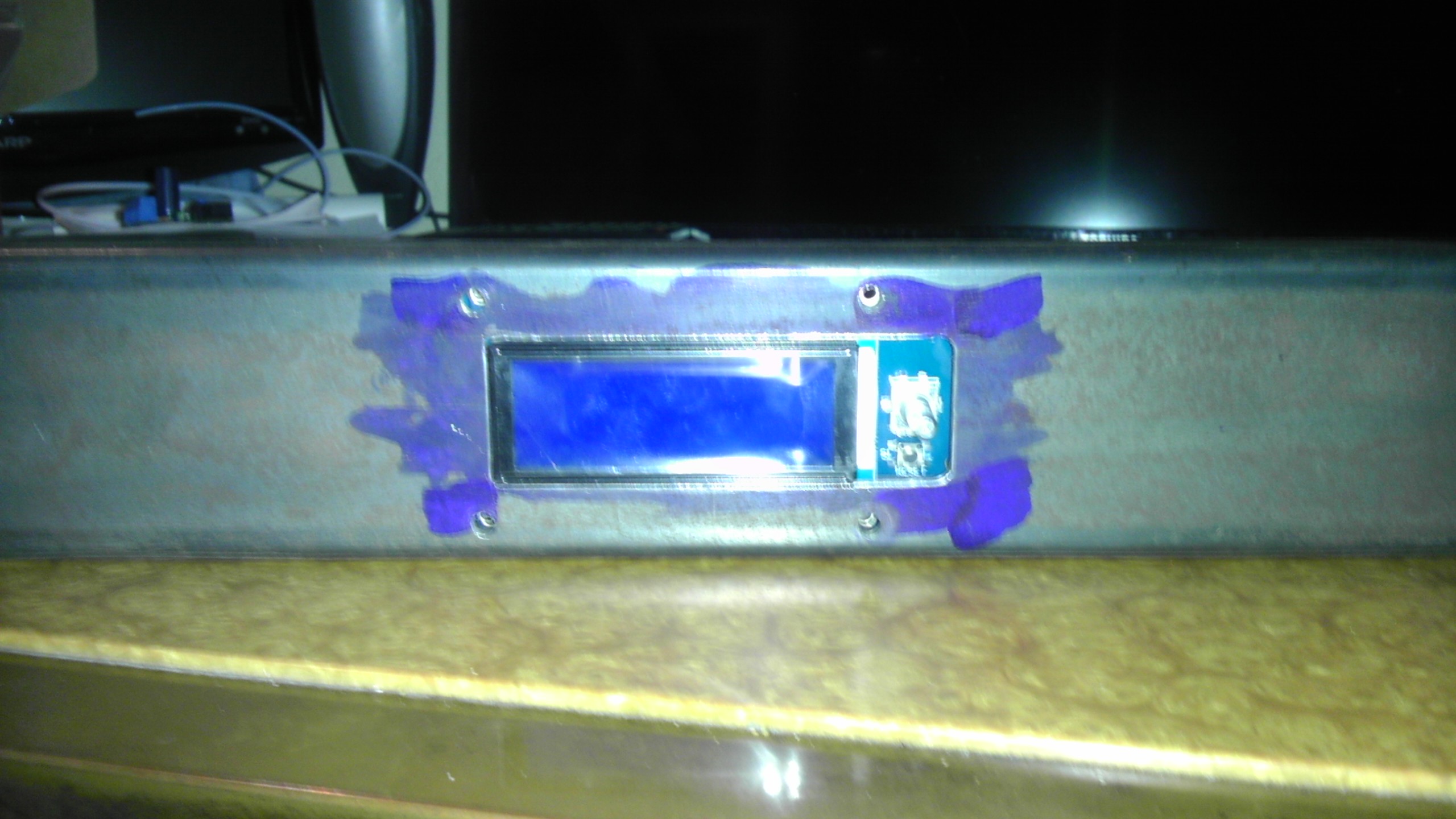
I nearly have completed fitting my LCD to my frame, and there are just a couple more machining matters to attend to before I can weld up the frame, which I hope to accomplish this weekend.
I nearly have completed fitting my LCD to my frame, and there are just a couple more machining matters to attend to before I can weld up the frame, which I hope to accomplish this weekend.
|
Re: Design nearly done - construction started... May 01, 2013 08:37PM |
Registered: 10 years ago Posts: 24 |
|
Re: Design nearly done - construction started... May 01, 2013 09:00PM |
Registered: 11 years ago Posts: 256 |
Thanks, Erich. I always say dive in with both feet - if you leave one behind it costs a lot to reattach it!  Seriously though, Beginning this project, I had certain goals, which as I go along i am discovering are not necessarily easily attained. So as I read through this forum and the wiki, and discover what potential issues I am going to encounter, I am trying to evolve my design to take all these things into consideration, which inevitably brings surprise projects into my overall effort. Hopefully at the end, this printer will do all that I want it to.
Seriously though, Beginning this project, I had certain goals, which as I go along i am discovering are not necessarily easily attained. So as I read through this forum and the wiki, and discover what potential issues I am going to encounter, I am trying to evolve my design to take all these things into consideration, which inevitably brings surprise projects into my overall effort. Hopefully at the end, this printer will do all that I want it to.
|
Re: Design nearly done - construction started... May 05, 2013 01:21PM |
Registered: 11 years ago Posts: 256 |
I'm getting close to welding up the frame. Hopefully sometime this week. Here's one last detail shot, showing the LCD set into the frame rail. It will get a cover plate, but I felt like keeping it as low profile as possible. I'm using the gadgets 3d complete kit for my basic electronics, and it comes with 2 different SD readers, though it involves a bit of a hack to use the micro SD shield along with the LCD. So that shield will be located conveniently just above the LCD on the frame, along with a port for the USB.
|
Re: Design nearly done - construction started... May 05, 2013 04:14PM |
Registered: 10 years ago Posts: 24 |
|
Re: Design nearly done - construction started... May 05, 2013 05:17PM |
Registered: 11 years ago Posts: 256 |
Thanks, Eric. It right now looks like about 14" front to back (X) 27" Y + or - and around 12" on the Z axis. I just now came from the shop where I drilled for mounting the Z motors and the rack carrier / cable guide. That means tomorrow after work we start burning metal! There are 41 parts of steel in the main frame ( a few of which I still need to make  ) and around 60 pieces of aluminum. There is also an upper frame that carries the extruder cold ends and the filament rollers, as well as supporting the upper covers. Things will surely speed up a bit once the frame is done because other than fitting rods, and flat spotting motor shafts, much of this starts to bolt together at that point. The upper frame will bolt to the main frame, because it is not part of the operational geometry, and that allows for final determination of the lengths and angles that will surely affect the success of all those Bowden tubes working together.
) and around 60 pieces of aluminum. There is also an upper frame that carries the extruder cold ends and the filament rollers, as well as supporting the upper covers. Things will surely speed up a bit once the frame is done because other than fitting rods, and flat spotting motor shafts, much of this starts to bolt together at that point. The upper frame will bolt to the main frame, because it is not part of the operational geometry, and that allows for final determination of the lengths and angles that will surely affect the success of all those Bowden tubes working together.
|
Re: Design nearly done - construction started... May 07, 2013 07:18PM |
Registered: 10 years ago Posts: 24 |
It's really nice to see your progress. As I said before, you are an inspiration for peoples like me, that would like to start to build and need a push. Your printer seems to be large compared with other. In fact, I think that there is a huge field for big printers since everybody prefer to work with small print areas.
If your printer works fine we could start a company!
If your printer works fine we could start a company!
|
Re: Design nearly done - construction started... May 07, 2013 07:40PM |
Registered: 11 years ago Posts: 256 |
There are a whole lot of things you have to do a bit differently to go big and accurate, which is my objective. Stiffness is #1,but you need to deal with temperatures and air movement / control, physical geometry, for this build there will be a lot of solutions to be engineered to cope with the will of plastic. Also on my mind of late is the issue of reliability, or more importantly, the issue of error handling. 4 days into a model and the power blinks, you don't want to have to start again. Not a promise for version 1, though I have some ideas for monitoring, which will then be expanded for error reporting, pause / restart etc. As fabrication on the frame progresses this week, I am starting to think a lot about electronic enhancements and ramps mods I need to do to make all this happen. I'm starting to feel a bit like Neo after he took the red pill...
|
Re: Design nearly done - construction started... May 07, 2013 08:37PM |
Registered: 10 years ago Posts: 24 |
|
Re: Design nearly done - construction started... May 09, 2013 05:12PM |
Registered: 11 years ago Posts: 256 |
Well, yesterday was fun - I spent the entire day putting a new (and totally different ) switch on my mill whose switch was failing. Different contacts, different altogether. I even had my friend, an electrician help and it still took us a bit of time, but all's well that ends well, and so to finish up I fitted the mill with a junction box to contain all the power cords.
So today after finishing machining the welds on the Z axis shelves, I was able to begin welding up the main frame, starting from the top. Tomorrow I hope to finish the upper and lower frames with the Z shelves in place...
) switch on my mill whose switch was failing. Different contacts, different altogether. I even had my friend, an electrician help and it still took us a bit of time, but all's well that ends well, and so to finish up I fitted the mill with a junction box to contain all the power cords.So today after finishing machining the welds on the Z axis shelves, I was able to begin welding up the main frame, starting from the top. Tomorrow I hope to finish the upper and lower frames with the Z shelves in place...
|
Re: Design nearly done - construction started... May 10, 2013 10:11AM |
Registered: 10 years ago Posts: 24 |
|
Re: Design nearly done - construction started... May 10, 2013 04:48PM |
Registered: 11 years ago Posts: 256 |
Let me just state for the record that I was wildly optimistic as to how long it takes me to weld stuff! I have been working on the part shown above all day, and have all but the outside open seams done. Part of the issue is that it is necessary to make sure this thing stays flat, and I am doing that by resting it on top of a machine I have whose top is a single piece of cast iron and is wide enough to lay this on, and then adjusting as necessary with a large mallet while the piece is still warm. So far, so good. I will likely break out the gas torch to do those edges, because the softer flame will not burn thru. Oh, if only there was a way to draw something up in a computer, and just have a machine spit it out for you.
|
Re: Design nearly done - construction started... May 10, 2013 05:07PM |
Registered: 11 years ago Posts: 381 |
I've heard of this new machine that will spit it out after you design it. I think they call it a reperap or something like that. Its a machine of the future maxxxmayhem. Imagine the day when we will be able to design something on a computer and then print it out in some sort of plastic. That would be cool! Any who, good job on the build so far I am watching as I said I would so thanks for the updates. I am in the midst of updating my printer to the new printrbot plus LC V2. My parts shall arrive tomorrow i believe. I'm still working on the 5-axis as well as the Elsa i9. Your work ethic is something of an inspiration to me. Keep up the good work buddy and I'm awaiting your next update.
--------------| For Everything |--------------------------
Check it out here:
[reprapsquad.wordpress.com].
---------| For Everything Prototype Related |------
Now featuring comp case mods:
[RepRapLab.wordpress.com]
--------------| Find us at Twitter|------------------------
@REPRAPSQUAD (RS Main)
[mobile.twitter.com]
@REPRAPSQUADHQ (ProtoLab)
[mobile.twitter.com]
|
Re: Design nearly done - construction started... May 11, 2013 02:17AM |
Registered: 17 years ago Posts: 392 |
Keep at it!  I call this the Land of the Prototypes. When people(I mean clients, not fellow builders) tell me it should only take a moment, and not cost much at all, I tell them - My good man, you are in the Land of the Prototypes now. It only takes a moment to wander in, but it costs a lot more to wander back out!
BTW, you mean oxyacetylene? Compared to TIG or MIG, that pumps a lot more BTUs into the metal, and would therefore cause more heat distortion, no? Don't know much about welding, but with my limited skills I can avoid heat distortion much more with MIG than oxyacetylene.
Tell us how it goes!
Edited 1 time(s). Last edit at 05/11/2013 02:53AM by Yvan.
Yvan
Singularity Machine
I call this the Land of the Prototypes. When people(I mean clients, not fellow builders) tell me it should only take a moment, and not cost much at all, I tell them - My good man, you are in the Land of the Prototypes now. It only takes a moment to wander in, but it costs a lot more to wander back out!BTW, you mean oxyacetylene? Compared to TIG or MIG, that pumps a lot more BTUs into the metal, and would therefore cause more heat distortion, no? Don't know much about welding, but with my limited skills I can avoid heat distortion much more with MIG than oxyacetylene.
Tell us how it goes!
Edited 1 time(s). Last edit at 05/11/2013 02:53AM by Yvan.
Yvan
Singularity Machine
|
Re: Design nearly done - construction started... May 11, 2013 09:10AM |
Registered: 11 years ago Posts: 256 |
Well, I will be testing on scraps first. To tell you the truth, it has been so long since I welded gas that A. I don't know if I have any gas, and B, I don't exactly remember the mix I like, but we'll just see what happens. I have been pretty successful in controlling distortion by careful quenching. But I don't want to push my luck at this point. I'm not totally ruling out tig for those areas if testing indicates that. One thing is clear, frame building (welded) is definitely something that requires a commitment of time and a great deal of patience, at least for prototyping. The good thing is that the process is going well, if not quickly, at this point. 
|
Re: Design nearly done - construction started... May 11, 2013 11:21AM |
Registered: 10 years ago Posts: 24 |
|
Re: Design nearly done - construction started... May 12, 2013 12:45PM |
Registered: 11 years ago Posts: 256 |
I got the Z shelves tacked and began running seams today for the top sub-assembly of my frame. It is pictured on top of the machine surface that I have been using as a flatness reference and I am pleased to report that it is flat and square. I'd have done more but my argon are gone , so that's mid week.
I appreciate everybody's support. I want to share my approach to building my printer in as close to real time as possible with this forum, as it is different, and I hope is of interest. Once I get past the frame, progress should accelerate considerably, and I look forward to this project taking shape, so stay tuned!
, so that's mid week.I appreciate everybody's support. I want to share my approach to building my printer in as close to real time as possible with this forum, as it is different, and I hope is of interest. Once I get past the frame, progress should accelerate considerably, and I look forward to this project taking shape, so stay tuned!
|
Re: Design nearly done - construction started... May 12, 2013 08:55PM |
Registered: 10 years ago Posts: 24 |
|
Re: Design nearly done - construction started... May 19, 2013 08:24PM |
Registered: 11 years ago Posts: 256 |
The upper and lower frame portions are now basically welded up. Over the course of the last week, I have re-engineered the design a bit. I had at first thought of using tubular corners but have decided instead upon heavy angle, as this gives me a better attachment point for my integral enclosure panels. The overall size remains the same. I also got an Arduino Nano to start playing around with some additional circuitry, I'll be using a number of LEDs to monitor the printer. Here are a couple of shots of the two frame sections, the one shows the approximate orientation to each other, though they are laying on their back, with the front of the machine pointing up in the air. I have a rush job this week, by next weekend, I hope to have the main frame assembled. I still have the upper assy. which holds the extruder motors.
|
Re: Design nearly done - construction started... May 19, 2013 08:46PM |
Registered: 10 years ago Posts: 24 |
Each time a read some news about your printer I got more excited to see the next step
Nice evolution by the way! And thanks for sharing your comments = experiences in what is better or what works better, like heavy angle instead tubular corners.
Eager to see the next steps for next week Keep it up! 
Nice evolution by the way! And thanks for sharing your comments = experiences in what is better or what works better, like heavy angle instead tubular corners.
Eager to see the next steps for next week
Keep it up!
|
Re: Design nearly done - construction started... May 25, 2013 07:08PM |
Registered: 11 years ago Posts: 256 |
While work on the frame continues... I thought I'd put up a pic of the completed 6064 driver from [www.massmind.org] , which I have mentioned a few times on this forum, as an option for those whose printers are using high amperage motors. Since my Z has 2 nema 23s pulling 2 amps each, I elected to go with this driver for that axis, as it is rated at 4 amps continuous, with a peak of around 4.5 amps. I am using the standard gadgets 3d drivers for the remaining steppers which are all nema 17. This driver is a kit and must be soldered together, however the instructions are thorough and assembly is straight forward.
|
Re: Design nearly done - construction started... May 25, 2013 08:17PM |
Registered: 10 years ago Posts: 24 |
 I am quite curious to see it
 |
Re: Design nearly done - construction started... May 25, 2013 08:59PM |
Registered: 11 years ago Posts: 256 |
I hope to return to the frame by wed or sooner. I had a rush job to get out in the shop, and I can't do any welding till it's out the door.  Remaining are the corner legs, which I have elected to make from 3/8" thick 3x3 angle, because I was becoming afraid I might be able to lift this thing by myself! Seriously though, they will provide not only the stiffness I want, but also simplify enclosing the build area to stabilize temperatures and allow for positive ventilation. I have pets in the office, and I'll be running a vent down thru the floor to the shop.
Remaining are the corner legs, which I have elected to make from 3/8" thick 3x3 angle, because I was becoming afraid I might be able to lift this thing by myself! Seriously though, they will provide not only the stiffness I want, but also simplify enclosing the build area to stabilize temperatures and allow for positive ventilation. I have pets in the office, and I'll be running a vent down thru the floor to the shop.


Sorry, only registered users may post in this forum.