Home
>
Reprappers
>
Topic
Banding problem
Posted by fractal5
|
Banding problem August 26, 2013 02:34PM |
Registered: 10 years ago Posts: 61 |
Hi,
I have a problem with my Prusa that I've had since it was new. I've struggled with this problem for at least half a year since the printer became operational. In brief, prints have a "banding" problem where each layer appears to be shifted on the X and/or Y axis. That is, for each layer it prints, it looks like the layer is "shifted" in some direction. By this I mean it is as if each layer starts printing at an offset from where the other layer was printed, maybe because of some mechanical play somewhere, see the attached pictures to make your own judgement. When printing the 20 mm box calibration object, this results in uneven faces that feel rough to the touch and in general just have poor aesthetic quality. Obviously this also results in poor precision for finer prints.
This is shown in the "banding_20mmbox.jpeg" attachment.
My printer is a MakerGear Mendel Prusa i2 that was bought new as a kit, with some modifications. There is a picture attached in "printer_setup.jpg".
I am using 1.75 mm PLA with a 0.35 mm nozzle at 0.2 mm layer height, at 185 degrees C for the hotend, 60 degrees C for the bed. The bed is covered with Kapton tape. The filament is bought from MakerGear.
Modifications:
* No lower end bearings on the Z axis: Should help with reducing wobble, if there is wobble (Z axis).
* No upper nut in the Z axis printed slider parts: Should help with reducing wobble, if there is wobble (Z axis).
* No spring inside the Z axis printed slider parts: No function when there is no upper nut.
* Acme rods: My M8 rods were slightly bent. My acme rods appear almost perfect when rolled on a glass surface.
* Non-printed idle pulleys: The printed pulleys had a problem with the belt climbing slightly on the edge, new ones do not have this problem.
* Printed part to hold a 40 mm fan (came with the kit, but with no printed part to mount it).
* Additional 80 mm fan.
* Printed filament holder with bearings inside the spool on an M8 threaded rod.
Please note that I had the same problem _before_ I started to make modifications, but these modifications I'm given to understand should only improve the machine in general, not make it worse.
My configuration for Slic3r is in the "config18.ini" attachment.
I am using Marlin firmware.
I have frequented the #reprap IRC channel and gotten some suggestions. I have checked at least the following:
* Everything is tightened down on the machine.
* All belts are tight with no play.
* There is no binding or unwanted resistance on any axes.
* There is no wobble/movement visible on the lower end of the Acme rods when using the Z axis.
* The Z couplers are preloaded. By this I mean they are stretched/pulled down before the screws are tightened on them (with the threaded rod in place). This is to prevent them being able to exert a "spring effect" on the Y carriage.
* I have lithium grease on the Acme threaded rods.
* I have oil on the smooth rods.
* I have done PID tuning for the hotend and for the bed.
* I have tried two different filament spools, both from MakerGear.
* I have measured the diameter of the filament with a digital caliper, it is exactly 1.75 mm and 1.74 mm in some places.
* I have measured the extruded filament, it is exactly 0.35 mm.
* I have done calibration, including having followed Triffid Hunter's calibration guide: [reprap.org]
* I have tried to increase and lower esteps from 476 to 466 and increase it to 487, there are no observable differences.
* I have tried to print at 210 degrees C, it made poorer results.
* I have tried different layer heights, 0.15, 0.2 and higher.
* I have tried printing with the bed completely turned off, it seems to give slightly improved results, but the banding problem is there, so it is not the underlying cause.
* I have tried to print with no fan; with the 40 mm fan at default settings; with the 40 mm fan at 100%, with both the 40 mm fan and the 80 mm fan at 100% speed.
* I have tried to reduce the travel speed from 170 to 50 mm/s for non print moves to see if there might be some play somewhere and with the intention that the effect of the play gets reduced when it does not jerk around as much. I did not observe any differences.
* I have tried different printing speeds for all paramters, most prints I have done are slow, at 20 mm/s. See the attached config18.ini file.
* I have checked that the z-screw on the gear on the extruder motor is tight and that there is no play.
* I have tried both the Sprinter and Marlin firmware.
* There is no audible, visible or tactile vibration on the machine, nor are there any unpleastant sounds from it.
The following result is interesting:
* I have mounted a laser on the back end of the extruder motor and observed the movements of the dot on the wall (about 6-7 meter away) when it extrudes (when it does not print, just extrude, no movement beyond extrusion): The dot moves in a horizontally oscillating pattern. The movement is minutiae. For this test I extruded 150 mm at 300 mm/min, towards the end of the 150 mm, the dot moved slightly up as well. I did the test twice, and reproduced the results. When the extrusion stops, the movement immediately stops on the laser dot on the wall. I am not sure what this overall result means, would this be normal behavior for it to move around like this, or is it an indication of something that is wrong? If so, what is wrong, how can it be corrected?
Finally I have also two other pictures (but I have many more, if it would be relevant to any discussion, advice or suggestions):
small_and_large.jpeg: A 20 mm box side by side with a 200% version of the 20 mm box.
yoda.jpeg: A print of the [www.thingiverse.com] "Yoda Lite" to demonstrate how poor quality prints I get, even after all this effort.
Marlin firmware configuration:
#define DEFAULT_AXIS_STEPS_PER_UNIT {52.4934,52.4934,2015.748031,476}
#define DEFAULT_MAX_FEEDRATE {500, 500, 3, 45} // (mm/sec)
#define DEFAULT_MAX_ACCELERATION {1000,1000,50,1000} // X, Y, Z, E maximum start speed for accelerated moves. E default values are good for skeinforge 40+, for older versions raise them a lot.
#define DEFAULT_ACCELERATION 450 // X, Y, Z and E max acceleration in mm/s^2 for printing moves
#define DEFAULT_RETRACT_ACCELERATION 450 // X, Y, Z and E max acceleration in mm/s^2 for retracts
// Offset of the extruders (uncomment if using more than one and relying on firmware to position when changing).
// The offset has to be X=0, Y=0 for the extruder 0 hotend (default extruder).
// For the other hotends it is their distance from the extruder 0 hotend.
// #define EXTRUDER_OFFSET_X {0.0, 20.00} // (in mm) for each extruder, offset of the hotend on the X axis
// #define EXTRUDER_OFFSET_Y {0.0, 5.00} // (in mm) for each extruder, offset of the hotend on the Y axis
// The speed change that does not require acceleration (i.e. the software might assume it can be done instantaneously)
#define DEFAULT_XYJERK 10.0 // (mm/sec)
#define DEFAULT_ZJERK 0.2 // (mm/sec)
#define DEFAULT_EJERK 2.5 // (mm/sec)
Any suggestions would be appreciated, thank you.
Edited 1 time(s). Last edit at 08/26/2013 02:48PM by fractal5.
I have a problem with my Prusa that I've had since it was new. I've struggled with this problem for at least half a year since the printer became operational. In brief, prints have a "banding" problem where each layer appears to be shifted on the X and/or Y axis. That is, for each layer it prints, it looks like the layer is "shifted" in some direction. By this I mean it is as if each layer starts printing at an offset from where the other layer was printed, maybe because of some mechanical play somewhere, see the attached pictures to make your own judgement. When printing the 20 mm box calibration object, this results in uneven faces that feel rough to the touch and in general just have poor aesthetic quality. Obviously this also results in poor precision for finer prints.
This is shown in the "banding_20mmbox.jpeg" attachment.

My printer is a MakerGear Mendel Prusa i2 that was bought new as a kit, with some modifications. There is a picture attached in "printer_setup.jpg".
I am using 1.75 mm PLA with a 0.35 mm nozzle at 0.2 mm layer height, at 185 degrees C for the hotend, 60 degrees C for the bed. The bed is covered with Kapton tape. The filament is bought from MakerGear.
Modifications:
* No lower end bearings on the Z axis: Should help with reducing wobble, if there is wobble (Z axis).
* No upper nut in the Z axis printed slider parts: Should help with reducing wobble, if there is wobble (Z axis).
* No spring inside the Z axis printed slider parts: No function when there is no upper nut.
* Acme rods: My M8 rods were slightly bent. My acme rods appear almost perfect when rolled on a glass surface.
* Non-printed idle pulleys: The printed pulleys had a problem with the belt climbing slightly on the edge, new ones do not have this problem.
* Printed part to hold a 40 mm fan (came with the kit, but with no printed part to mount it).
* Additional 80 mm fan.
* Printed filament holder with bearings inside the spool on an M8 threaded rod.
Please note that I had the same problem _before_ I started to make modifications, but these modifications I'm given to understand should only improve the machine in general, not make it worse.
My configuration for Slic3r is in the "config18.ini" attachment.
I am using Marlin firmware.
I have frequented the #reprap IRC channel and gotten some suggestions. I have checked at least the following:
* Everything is tightened down on the machine.
* All belts are tight with no play.
* There is no binding or unwanted resistance on any axes.
* There is no wobble/movement visible on the lower end of the Acme rods when using the Z axis.
* The Z couplers are preloaded. By this I mean they are stretched/pulled down before the screws are tightened on them (with the threaded rod in place). This is to prevent them being able to exert a "spring effect" on the Y carriage.
* I have lithium grease on the Acme threaded rods.
* I have oil on the smooth rods.
* I have done PID tuning for the hotend and for the bed.
* I have tried two different filament spools, both from MakerGear.
* I have measured the diameter of the filament with a digital caliper, it is exactly 1.75 mm and 1.74 mm in some places.
* I have measured the extruded filament, it is exactly 0.35 mm.
* I have done calibration, including having followed Triffid Hunter's calibration guide: [reprap.org]
* I have tried to increase and lower esteps from 476 to 466 and increase it to 487, there are no observable differences.
* I have tried to print at 210 degrees C, it made poorer results.
* I have tried different layer heights, 0.15, 0.2 and higher.
* I have tried printing with the bed completely turned off, it seems to give slightly improved results, but the banding problem is there, so it is not the underlying cause.
* I have tried to print with no fan; with the 40 mm fan at default settings; with the 40 mm fan at 100%, with both the 40 mm fan and the 80 mm fan at 100% speed.
* I have tried to reduce the travel speed from 170 to 50 mm/s for non print moves to see if there might be some play somewhere and with the intention that the effect of the play gets reduced when it does not jerk around as much. I did not observe any differences.
* I have tried different printing speeds for all paramters, most prints I have done are slow, at 20 mm/s. See the attached config18.ini file.
* I have checked that the z-screw on the gear on the extruder motor is tight and that there is no play.
* I have tried both the Sprinter and Marlin firmware.
* There is no audible, visible or tactile vibration on the machine, nor are there any unpleastant sounds from it.
The following result is interesting:
* I have mounted a laser on the back end of the extruder motor and observed the movements of the dot on the wall (about 6-7 meter away) when it extrudes (when it does not print, just extrude, no movement beyond extrusion): The dot moves in a horizontally oscillating pattern. The movement is minutiae. For this test I extruded 150 mm at 300 mm/min, towards the end of the 150 mm, the dot moved slightly up as well. I did the test twice, and reproduced the results. When the extrusion stops, the movement immediately stops on the laser dot on the wall. I am not sure what this overall result means, would this be normal behavior for it to move around like this, or is it an indication of something that is wrong? If so, what is wrong, how can it be corrected?
Finally I have also two other pictures (but I have many more, if it would be relevant to any discussion, advice or suggestions):
small_and_large.jpeg: A 20 mm box side by side with a 200% version of the 20 mm box.
yoda.jpeg: A print of the [www.thingiverse.com] "Yoda Lite" to demonstrate how poor quality prints I get, even after all this effort.
Marlin firmware configuration:
#define DEFAULT_AXIS_STEPS_PER_UNIT {52.4934,52.4934,2015.748031,476}
#define DEFAULT_MAX_FEEDRATE {500, 500, 3, 45} // (mm/sec)
#define DEFAULT_MAX_ACCELERATION {1000,1000,50,1000} // X, Y, Z, E maximum start speed for accelerated moves. E default values are good for skeinforge 40+, for older versions raise them a lot.
#define DEFAULT_ACCELERATION 450 // X, Y, Z and E max acceleration in mm/s^2 for printing moves
#define DEFAULT_RETRACT_ACCELERATION 450 // X, Y, Z and E max acceleration in mm/s^2 for retracts
// Offset of the extruders (uncomment if using more than one and relying on firmware to position when changing).
// The offset has to be X=0, Y=0 for the extruder 0 hotend (default extruder).
// For the other hotends it is their distance from the extruder 0 hotend.
// #define EXTRUDER_OFFSET_X {0.0, 20.00} // (in mm) for each extruder, offset of the hotend on the X axis
// #define EXTRUDER_OFFSET_Y {0.0, 5.00} // (in mm) for each extruder, offset of the hotend on the Y axis
// The speed change that does not require acceleration (i.e. the software might assume it can be done instantaneously)
#define DEFAULT_XYJERK 10.0 // (mm/sec)
#define DEFAULT_ZJERK 0.2 // (mm/sec)
#define DEFAULT_EJERK 2.5 // (mm/sec)
Any suggestions would be appreciated, thank you.
Edited 1 time(s). Last edit at 08/26/2013 02:48PM by fractal5.
|
Re: Banding problem August 26, 2013 05:31PM |
Two possible causes come to mind;
- your z-axis motors get disabled (check configuration.h, #define DISABLE_E false // For all extruders)
- your z-axis stepper driver gets too hot and skips steps. Check if the driver gets hotter than the other drivers, if so reduce current to the motors and check your wiring (the steppers must be connected in series, not parallel).
|
Re: Banding problem August 26, 2013 05:59PM |
Registered: 10 years ago Posts: 61 |
rapsac Wrote:
-------------------------------------------------------
> Two possible causes come to mind;
> - your z-axis motors get disabled (check
> configuration.h, #define DISABLE_E false // For
> all extruders)
> - your z-axis stepper driver gets too hot and
> skips steps. Check if the driver gets hotter than
> the other drivers, if so reduce current to the
> motors and check your wiring (the steppers must be
> connected in series, not parallel).
Thanks for that adivce, I'm not sure I follow you though.
Should I have "#define DISABLE_E false // For all extruders" in my Configuration.h, or should I comment it out?
I have:
// Disables axis when it's not being used.
#define DISABLE_X false
#define DISABLE_Y false
#define DISABLE_Z false
#define DISABLE_E false // For all extruders
So these are _not_ commented out in my configuration, should I change that?
|
Re: Banding problem August 26, 2013 06:14PM |
// Disables axis when it's not being used.
#define DISABLE_X false
#define DISABLE_Y false
#define DISABLE_Z false
#define DISABLE_E false // For all extruders
This is correct. The default setting in (my) marlin is
#define DISABLE_Z true
and that would cause z-axis problems.
So i can only think of overheating stepper driver or current through the stepper too low (by connecting the steppers parallel instead of in series).
|
Re: Banding problem August 26, 2013 06:29PM |
Registered: 10 years ago Posts: 61 |
rapsac Wrote:
-------------------------------------------------------
> // Disables axis when it's not being used.
> #define DISABLE_X false
> #define DISABLE_Y false
> #define DISABLE_Z false
> #define DISABLE_E false // For all extruders
>
> This is correct. The default setting in (my)
> marlin is
> #define DISABLE_Z true
> and that would cause z-axis problems.
> So i can only think of overheating stepper driver
> or current through the stepper too low (by
> connecting the steppers parallel instead of in
> series).
This is what my board looks like (see ramps_arduino.jpg attachment). The upper left cable goes to my Z axis motors, and is split just like in this diagram before actually reaching the stepper motors:
[reprap.org]
Is that correct?
Edited 2 time(s). Last edit at 08/26/2013 06:31PM by fractal5.
-------------------------------------------------------
> // Disables axis when it's not being used.
> #define DISABLE_X false
> #define DISABLE_Y false
> #define DISABLE_Z false
> #define DISABLE_E false // For all extruders
>
> This is correct. The default setting in (my)
> marlin is
> #define DISABLE_Z true
> and that would cause z-axis problems.
> So i can only think of overheating stepper driver
> or current through the stepper too low (by
> connecting the steppers parallel instead of in
> series).
This is what my board looks like (see ramps_arduino.jpg attachment). The upper left cable goes to my Z axis motors, and is split just like in this diagram before actually reaching the stepper motors:
[reprap.org]
Is that correct?

Edited 2 time(s). Last edit at 08/26/2013 06:31PM by fractal5.
|
Re: Banding problem August 26, 2013 07:37PM |
I'm only familiar with sanguinololu. If your ramps uses one driver for both z motors you should connect them winding by winding in series.
Eg if your motors have red/blue/green/yellow cables and red/blue and green/yellow are the connections of the 2 windings you should wire
- red from the 1st motor to the left most stepper connector pin on the ramps
- blue from the 1st motor to red from the 2nd motor
- blue from the 2nd motor to the 2nd pin on the ramps
- green 1st to pin 3 ramps
- yellow 1st to green 2nd
- yellow 2nd to pin4
Look at the colors and pin connections of the x-axis motor for your color combinations.
|
Re: Banding problem August 26, 2013 08:11PM |
Registered: 10 years ago Posts: 61 |
rapsac Wrote:
-------------------------------------------------------
> I'm only familiar with sanguinololu. If your ramps
> uses one driver for both z motors you should
> connect them winding by winding in series.
> Eg if your motors have red/blue/green/yellow
> cables and red/blue and green/yellow are the
> connections of the 2 windings you should wire
> - red from the 1st motor to the left most stepper
> connector pin on the ramps
> - blue from the 1st motor to red from the 2nd
> motor
> - blue from the 2nd motor to the 2nd pin on the
> ramps
>
> - green 1st to pin 3 ramps
> - yellow 1st to green 2nd
> - yellow 2nd to pin4
> Look at the colors and pin connections of the
> x-axis motor for your color combinations.
Forgive me but this seems highly unusual. I have never heard that the stepper motors should be connected in series before, on the contrary I have the diagram I provided a link to that suggests the opposite. Do you have a reference for this, some guide, tutorial or document that states this?
|
Re: Banding problem August 26, 2013 09:31PM |
Registered: 11 years ago Posts: 313 |
rapsac Wrote:
-------------------------------------------------------
> I'm only familiar with sanguinololu. If your ramps
> uses one driver for both z motors you should
> connect them winding by winding in series.
> Eg if your motors have red/blue/green/yellow
> cables and red/blue and green/yellow are the
> connections of the 2 windings you should wire
> - red from the 1st motor to the left most stepper
> connector pin on the ramps
> - blue from the 1st motor to red from the 2nd
> motor
> - blue from the 2nd motor to the 2nd pin on the
> ramps
>
> - green 1st to pin 3 ramps
> - yellow 1st to green 2nd
> - yellow 2nd to pin4
> Look at the colors and pin connections of the
> x-axis motor for your color combinations.
connecting them in series will 1/2 the voltage to each motor,
you dont do this
|
Re: Banding problem August 27, 2013 05:59AM |
Uhm, the torque the motors produce is only related to the CURRENT through the motors, not by the voltage. By wiring them in series both motors will reach their full torque even when sharing one driver, without addind heat to the driver. By wiring them parallel you only get 50% of the torque + likely an overheating driver by turning up vref to get as much out of the driver as possible.
|
Re: Banding problem August 27, 2013 10:41AM |
Registered: 10 years ago Posts: 61 |
rapsac Wrote:
-------------------------------------------------------
> Uhm, the torque the motors produce is only related
> to the CURRENT through the motors, not by the
> voltage. By wiring them in series both motors will
> reach their full torque even when sharing one
> driver, without addind heat to the driver. By
> wiring them parallel you only get 50% of the
> torque + likely an overheating driver by turning
> up vref to get as much out of the driver as
> possible.
What temperatures am I supposed to see on the heatsinks of the drivers?
Do you have any reference for anyone else that use a Prusa setup with the Z motors connected in series?
|
Re: Banding problem August 27, 2013 02:18PM |
If you really want to understand why you want to connect them in series lookup inductance on wikipedia. The reprap guides often show parallel connections. I guess that is because in the old days stepper motors were often recycled printer motors that have a high resistance and required 12V or more to reach full current. Current motors are low resistance and have a working current of 1.5-2.5A, reaching their rated current at 2-4V.
I'm running my 2.5A motors at 1.2A (X-Y-2xZ) and my extruder at 0.8A. All drivers have a small heatsink and get a little hot, i can touch them but i cant hold them for more than 10 sec.
I'm running my 2.5A motors at 1.2A (X-Y-2xZ) and my extruder at 0.8A. All drivers have a small heatsink and get a little hot, i can touch them but i cant hold them for more than 10 sec.
|
Re: Banding problem August 28, 2013 07:41AM |
Registered: 10 years ago Posts: 194 |
rapsac Wrote:
-------------------------------------------------------
> Uhm, the torque the motors produce is only related
> to the CURRENT through the motors, not by the
> voltage.
Wouldn't that be only true when the voltage is fixed/constant? In other words, for a given voltage, we will obviously get more torque with more current and less torque with less current.
I have to admit I'm no expert of stepper motor, but it just doesn't sound right that the motor can produce the same amount of torque with the same amount of current when you cut the voltage down to a half...
I understand a half of the initial voltage may still be within the operational voltage range for the motors, but that's just for the matter of whether the motor will operate properly or not. Now with the lower voltage the motors will need to draw more current, or produce less torque, or do a little bit of both.
So, basically what I am saying is torque would be related to V x I, not I alone.
When I saw your suggestion of connecting motors in series, I first thought it did not make sense at all. But then again, after reading it more, I think it does make sense.. If today's stepper motors have low operating voltage like you said, halving the input voltage by connecting two identical motors in series would work, I think.
However, I wonder what the benefit of doing that is. As I said above, with the serial connection, since the voltage across each motor is half of Vref, the circuit will have to draw twice as much current. If we connect the motors in parallel, the voltage across each motor is Vref, so each of them only draw half as much current. However, since each motor draws half as much current independently, the overall current consumption is the same (since two time half is one).
Again, I am not saying series connection will not work, but I don't know what the real gain is...
Since stepper motors have the max torque output, it would be certainly possible to provide more current or higher voltage than needed and have the extra energy wasted (generate heat rather than generating torque). Having said that, if the lowest Vref we can set is way too high for the stepper motors we use, I think connecting motors in series could be beneficial - it would allow us to halve that Vref voltage. However, I never had a problem of Vref voltage being too high for my motors with my Pololus drivers - I can easily reduce it to the point where my motors won't run at all.
Or, I guess halving the voltage could make Vref adjustment a little bit easier? I always had trouble turning the trimpot only 1/8 of a turn or 1/16 of a turn. However, with this serial connection, my 1/8 of a turn effective becomes 1/16 of a turn and my 1/16 of a turn becomes 1/32 of a turn... Hmm.. that's actually cool
By the way, my printer has 2 Z motors, and they are connected to the same Pololu driver in parallel, which I think actually is the standard connection configuration. My Z motors are the coldest running motors in my printer, and I have to admit that I've never touched the driver heat sink so I don't know how hot/cold they run - when I see a heat sink, it's a sign telling me "do not touch me" I guess they are doing okay (knock on wood) since I never had a problem.
-------------------------------------------------------
> Uhm, the torque the motors produce is only related
> to the CURRENT through the motors, not by the
> voltage.
Wouldn't that be only true when the voltage is fixed/constant? In other words, for a given voltage, we will obviously get more torque with more current and less torque with less current.
I have to admit I'm no expert of stepper motor, but it just doesn't sound right that the motor can produce the same amount of torque with the same amount of current when you cut the voltage down to a half...
I understand a half of the initial voltage may still be within the operational voltage range for the motors, but that's just for the matter of whether the motor will operate properly or not. Now with the lower voltage the motors will need to draw more current, or produce less torque, or do a little bit of both.
So, basically what I am saying is torque would be related to V x I, not I alone.
When I saw your suggestion of connecting motors in series, I first thought it did not make sense at all. But then again, after reading it more, I think it does make sense.. If today's stepper motors have low operating voltage like you said, halving the input voltage by connecting two identical motors in series would work, I think.
However, I wonder what the benefit of doing that is. As I said above, with the serial connection, since the voltage across each motor is half of Vref, the circuit will have to draw twice as much current. If we connect the motors in parallel, the voltage across each motor is Vref, so each of them only draw half as much current. However, since each motor draws half as much current independently, the overall current consumption is the same (since two time half is one).
Again, I am not saying series connection will not work, but I don't know what the real gain is...
Since stepper motors have the max torque output, it would be certainly possible to provide more current or higher voltage than needed and have the extra energy wasted (generate heat rather than generating torque). Having said that, if the lowest Vref we can set is way too high for the stepper motors we use, I think connecting motors in series could be beneficial - it would allow us to halve that Vref voltage. However, I never had a problem of Vref voltage being too high for my motors with my Pololus drivers - I can easily reduce it to the point where my motors won't run at all.
Or, I guess halving the voltage could make Vref adjustment a little bit easier? I always had trouble turning the trimpot only 1/8 of a turn or 1/16 of a turn. However, with this serial connection, my 1/8 of a turn effective becomes 1/16 of a turn and my 1/16 of a turn becomes 1/32 of a turn... Hmm.. that's actually cool
By the way, my printer has 2 Z motors, and they are connected to the same Pololu driver in parallel, which I think actually is the standard connection configuration. My Z motors are the coldest running motors in my printer, and I have to admit that I've never touched the driver heat sink so I don't know how hot/cold they run - when I see a heat sink, it's a sign telling me "do not touch me"
I guess they are doing okay (knock on wood) since I never had a problem.
|
Re: Banding problem August 28, 2013 08:35AM |
Registered: 11 years ago Posts: 342 |
The vref for the one driver running my two Z motors is set to 0.4v just like the rest of my single motor axises. So yes the they are sharing this, but we can get away with this because the threaded rods provide a mechanical advantage to this axis.
Yamster Wrote:
-------------------------------------------------------
> Wouldn't that be only true when the voltage is
> fixed/constant? In other words, for a given
> voltage, we will obviously get more torque with
> more current and less torque with less current.
>
> I have to admit I'm no expert of stepper motor,
> but it just doesn't sound right that the motor can
> produce the same amount of torque with the same
> amount of current when you cut the voltage down to
> a half...
>
> I understand a half of the initial voltage may
> still be within the operational voltage range for
> the motors, but that's just for the matter of
> whether the motor will operate properly or not.
> Now with the lower voltage the motors will need to
> draw more current, or produce less torque, or do a
> little bit of both.
>
> So, basically what I am saying is torque would be
> related to V x I, not I alone.
>
>
> When I saw your suggestion of connecting motors in
> series, I first thought it did not make sense at
> all. But then again, after reading it more, I
> think it does make sense.. If today's stepper
> motors have low operating voltage like you said,
> halving the input voltage by connecting two
> identical motors in series would work, I think.
>
> However, I wonder what the benefit of doing that
> is. As I said above, with the serial connection,
> since the voltage across each motor is half
|
Re: Banding problem August 28, 2013 07:43PM |
I found more on the z motor wiring here.
By wiring the motors parallel each motor only gets 50% of the current, and only produce 50% of the possible torque. btw the stepper drivers limit the current to the value you set with the vref potentiometer. When the current matches the setpoint the driver switches off until the current is below the setpoint(- some hysteresis). The voltage over the motor during switching goes from 12V (when driver switches on), rapidly dropping down to (motor winding resistance (or better; impedance) X set current) and then the driver switches off. By wiring the motors parallel the current reaches the setpoint faster (as the resistance is only half of that of a single motor), so you could theoretically reach higher speeds this way. But the arduino is too slow to notice that effect, and the motors are to weak at only 50% torque to gain that advantage. For series connected wirings you double the resistance (again; better impedance), slowing the max rpms but doubling the torque at lower speeds.
And although you already have
#define DISABLE_Z false
in your configuration.h here's why you should do that;
stepper motors are not cogless motors, when you turn the motors by hand you notice the bumps. When the motor reaches the top of such a bump while micro stepping and you switch the driver off the motor can/will rotate a little to get off the bump (like a ball rolling down a hill). But there is no way to predict if it will turn clockwise or counter clockwise. If you have 2 motors one can turn clockwise, and the other could turn counter clockwise, and your bed levelling is gone.
I've read that both points (wiring and DISABLE_Z) are wrong in the built manuals on reprap.
|
Re: Banding problem August 28, 2013 07:45PM |
Registered: 11 years ago Posts: 342 |
Can you please tell us what firmware and slicer you are using and attach their configuration files? Make sure they are what was loaded on your RAMPS and set in your slicer when you did the print above with them. If don’t still have the configs from that print, do another one please and post a new pic made with your latest configs.
|
Re: Banding problem August 28, 2013 08:08PM |
Registered: 11 years ago Posts: 342 |
fractal5, don't miss my post below rapsac's and above this one.
rapsac, I find you post interesting. I had come to believe that the pololus controlled current by using a feedback circuit that connects from the output back to the base. This would result in continual adjustments without shutting off. I had also thought they provided 1 amp to the Z motors and each one of them consumed half that current to produce half their rated torque. Wired in series the resistance would be double, also resulting in half the torque. That said, I know there are differences between current flowing though a resistor and an inductor. This may come into play here. Maybe someone will come along who knows and school us.
rapsac Wrote:
-------------------------------------------------------
> I found more on the z motor wiring
> [url=http://forums.reprap.org/read.php?151,94179,9
> 4347]here.[/url]
> By wiring the motors parallel each motor only gets
> 50% of the current, and only produce 50% of the
> possible torque. btw the stepper drivers limit
> the current to the value you set with the vref
> potentiometer. When the current matches the
> setpoint the driver switches off until the current
> is below the setpoint(- some hysteresis). The
> voltage over the motor during switching goes from
> 12V (when driver switches on), rapidly dropping
> down to (motor winding resistance (or better;
> impedance) X set current) and then the driver
> switches off. By wiring the motors parallel the
> current reaches the setpoint faster (as the
> resistance is only half of that of a single
> motor), so you could theoretically reach higher
> speeds this way. But the arduino is too slow to
> notice that effect, and the motors are to weak at
> only 50% torque to gain that advantage. For series
> connected wirings you double the resistance
> (again; better impedance), slowing the max rpms
> but doubling the torque at lower speeds.
>
> And although you already have
> #define DISABLE_Z false
> in your configuration.h here's why you should do
> that;
> stepper motors are not cogless motors, when you
> turn the motors by hand you notice the bumps. When
> the motor reaches the top of such a bump while
> micro stepping and you switch the driver off the
> motor can/will rotate a little to get off the bump
> (like a ball rolling down a hill). But there is no
> way to predict if it will turn clockwise or
> counter clockwise. If you have 2 motors one can
> turn clockwise, and the other could turn counter
> clockwise, and your bed levelling is gone.
>
> I've read that both points (wiring and DISABLE_Z)
> are wrong in the built manuals on reprap.
|
Re: Banding problem August 28, 2013 09:33PM |
The motors are rated at a specific current, resulting in a max. voltage (ohms law U=I*R), usually the voltage is 2-4V. If you connect 2 in series directly to 12V you would still overdrive the motors and burn them out eventually. The drivers (all recent drivers) use a H-bridge per winding and can only be turned off/on. Long ago sometimes power opamps were used that could drive a winding with exactly the needed current. You needed a BIG heatsink on such drivers (heat generated by driver = U*I, in this case that would be U=12-4V of motor, I=1.5A? = 12W). The h-bridges are low resistance switches (low RDSON mosfets), only ~0.5V is lost over the bridges (P = 0.5 * 1.5A? = 0,75W, + some switching losses as the mosfets have higher losses during switching). You can find the actual RDSON & resulting voltage drop in the datasheet of your driver ic.
|
Re: Banding problem August 29, 2013 10:09AM |
Registered: 10 years ago Posts: 61 |
appdev007 Wrote:
-------------------------------------------------------
> Can you please tell us what firmware and slicer
> you are using and attach their configuration
> files? Make sure they are what was loaded on your
> RAMPS and set in your slicer when you did the
> print above with them. If don’t still have the
> configs from that print, do another one please and
> post a new pic made with your latest configs.
Firmware version: Marlin 1.0.0
Slic3r: 0.9.8 for most prints, now using 0.9.10b, I've also tried a couple other versions.
Pictures below are with Marlin 1.0.0 and Slic3r 0.9.10b using the attached configuration file Configuration.h for Marlin 1.0.0, and config18.ini for Slic3r. The other header files for Marlin have not been modified. Cooling: 40 mm fan and 80 mm fan.
As suggested by appdev007, for this print I'm also using two physical PSUs to mitigate any possibility of my PSU not being able to provide enough current. With this setup I'm using a PSU that delivers at least 14 amp on the 11 A input and another PSU that delivers at least 16 amps on the 5 A input (by "at least" I'm taking the minimum of "12V1" and "12V2" as stated on the specifications of the PSUs respectively).
Here is the result:
Edited 2 time(s). Last edit at 08/29/2013 10:10AM by fractal5.
-------------------------------------------------------
> Can you please tell us what firmware and slicer
> you are using and attach their configuration
> files? Make sure they are what was loaded on your
> RAMPS and set in your slicer when you did the
> print above with them. If don’t still have the
> configs from that print, do another one please and
> post a new pic made with your latest configs.
Firmware version: Marlin 1.0.0
Slic3r: 0.9.8 for most prints, now using 0.9.10b, I've also tried a couple other versions.
Pictures below are with Marlin 1.0.0 and Slic3r 0.9.10b using the attached configuration file Configuration.h for Marlin 1.0.0, and config18.ini for Slic3r. The other header files for Marlin have not been modified. Cooling: 40 mm fan and 80 mm fan.
As suggested by appdev007, for this print I'm also using two physical PSUs to mitigate any possibility of my PSU not being able to provide enough current. With this setup I'm using a PSU that delivers at least 14 amp on the 11 A input and another PSU that delivers at least 16 amps on the 5 A input (by "at least" I'm taking the minimum of "12V1" and "12V2" as stated on the specifications of the PSUs respectively).
Here is the result:

Edited 2 time(s). Last edit at 08/29/2013 10:10AM by fractal5.
|
Re: Banding problem August 29, 2013 10:22AM |
Registered: 10 years ago Posts: 61 |
I have some interesting news. Someone on IRC suggested I should print the same box, at 300% scaled size, in "Spiral vase" mode. I did this, and got relatively very good results. There are some artifacts on the faces, which seem to be a completely different problem compared to my previous "banding problem", however the walls/faces themselves appear smooth, with little or no banding, and the corners appear much better:
This first picture "dzy4.jpg" is of the 20 mm box calibration object, at 300% scaled size, using "Spiral vase" mode. I am using the config18.ini file as configuration, however with bed turned off and at 0.25 mm layer height (this was also suggested by the same person).
[img713.imageshack.us]
This second picture "0nzn.jpg" is again of the 20 mm box calibration object, at 300% scaled size, using "Spiral vase" mode. I am using the config18.ini file as configuration again, however with the bed at 60 degrees C, and at 0.20 mm layer height. This 0.20 mm layer print is to the left in the picture, to the right is the 0.25 mm print before that, to compare them side by side.
[img5.imageshack.us]
Does this suggest that my esteps might be the problem after all, when it can print walls that look like that, as long as there is no infill?
Edited 3 time(s). Last edit at 08/29/2013 10:24AM by fractal5.
|
Re: Banding problem August 29, 2013 11:19AM |
Admin Registered: 14 years ago Posts: 17 |
Both of these prints are miles better than your previous examples. It makes sense that the 0.2mm layer /60C bed print looks slightly worse, as the slower cooling of the layers can contribute to the slightly 'sloppy' looking corners.
The interesting questions now are why the 60C has that inconsistent banding, while the 20C does not. It's certainly not the traditional bent-threaded-rods Z-wobble, as it's too inconsistent.
The biggest difference between these prints, and all your previous prints is the lack of infill. No infill means it's a much shorter print, less time for the PSU/steppers/drivers to warm up, and less heat in general.
The big difference between those two prints is the bed temp. the layer height is different, but only by %20.
The difference between a 20C bed and a 60C bed is pretty big, in terms of ambient heat, and draw on the PSU.
If it was related to insufficient cooling, I'd expect the problem to be worse earlier in the print, closer to the bed.
It appears that it *is* worse closer to the bed, but sitll pretty inconsistent. Do these prints have different surface quality on the sides that were facing fans, compared to the sides getting less airflow?
My second guess is that the stepper motor is missing a few steps occasionaly. If you forcibly pull the filamtent durning a print, are you able to make it slip/skip some extrusion?
To test whether this is related to the PSU not supplying enough current, you could try a print with power for the bed supplied from a separate PSU.
It'd also be worth printing the identical gcode twice, but with one at a 60C bed, and the other no bed heat. You can
slice the gcode with no bed-heat, and then turn the bed heat on manually for one of the prints.
I don't expect the 0.05mm layer height difference between these two tests is a big deal, but another pair of test prints could confirm that.
Good luck, let me know what you find.
Bill
|
Re: Banding problem August 29, 2013 01:18PM |
Registered: 13 years ago Posts: 79 |
Hi fractal5,
Before you go messing any more with your machine you might want to try adjusting your Slic3r settings. When using Slic3r you should always look at the top of your Gcode. I can see no rhyme or reason in the way it calculates extrusion widths. I sliced an object using your .15 height setting and this what I got.
; layer_height = 0.15
; perimeters = 3
; top_solid_layers = 3
; bottom_solid_layers = 3
; fill_density = 0.25
; perimeter_speed = 20
; infill_speed = 20
; travel_speed = 50
; nozzle_diameter = 0.35
; filament_diameter = 1.75
; extrusion_multiplier = 1.0
; perimeters extrusion width = 0.59mm
; infill extrusion width = 0.67mm
; solid infill extrusion width = 0.59mm
; top infill extrusion width = 0.59mm
; first layer extrusion width = 0.30mm
The extrusion widths are close to double the size of your nozzle so rather than drawing the filament along the tracks at ~nozzle width it has to push the filament out to cover the widened path which ends up making a big mess. Also you’re your speed settings are all very slow. Can’t you get a workable Slic3r ini file from Makergear? I would think it would be part of their support program.
After seeing your last post I reset your Slic3r settings height to .25 and re-sliced and got this.
; layer_height = 0.25
; perimeters = 3
; top_solid_layers = 3
; bottom_solid_layers = 3
; fill_density = 0.25
; perimeter_speed = 20
; infill_speed = 20
; travel_speed = 50
; nozzle_diameter = 0.35
; filament_diameter = 1.75
; extrusion_multiplier = 1.0
; perimeters extrusion width = 0.39mm
; infill extrusion width = 0.39mm
; solid infill extrusion width = 0.39mm
; top infill extrusion width = 0.39mm
; first layer extrusion width = 0.30mm
Notice that the extrusion width are close to what they should be?
You can manually set the extrusion width in the advanced tab under print settings in Slic3r. I would do that before messing around with anything else.
Blog
|
Re: Banding problem August 29, 2013 02:41PM |
Registered: 10 years ago Posts: 61 |
bill2or3 Wrote:
-------------------------------------------------------
> Both of these prints are miles better than your
> previous examples. It makes sense that the 0.2mm
> layer /60C bed print looks slightly worse, as the
> slower cooling of the layers can contribute to the
> slightly 'sloppy' looking corners.
>
> The interesting questions now are why the 60C has
> that inconsistent banding, while the 20C does not.
> It's certainly not the traditional
> bent-threaded-rods Z-wobble, as it's too
> inconsistent.
>
> The biggest difference between these prints, and
> all your previous prints is the lack of infill.
> No infill means it's a much shorter print, less
> time for the PSU/steppers/drivers to warm up, and
> less heat in general.
>
> The big difference between those two prints is the
> bed temp. the layer height is different, but only
> by %20.
Bruce has an interesting point about the extrusion width. The 0.25 mm layer height gives much closer to ideal values than 0.2 mm does, maybe this is (part of) the reason why the 0.25 print looks better, the other part being the cooling.
It was also pointed out by a friend of mine that the temperature of the bed appears to vary (it is PID tuned) slightly, with the bed getting turning on and off like that, which could cause some artifacts as the temperature fluctuates?
>
> The difference between a 20C bed and a 60C bed is
> pretty big, in terms of ambient heat, and draw on
> the PSU.
> If it was related to insufficient cooling, I'd
> expect the problem to be worse earlier in the
> print, closer to the bed.
> It appears that it *is* worse closer to the bed,
> but sitll pretty inconsistent. Do these prints
> have different surface quality on the sides that
> were facing fans, compared to the sides getting
> less airflow?
I just checked both prints, there appears to be little or no difference on the sides that got less airflow. However if any sides were getting less air flow or not, that is actually a bit hard for me to determine. Looking at the box from above, the top and bottom would be facing directly a fan on both side at a perpendicular angle. The sides would still see air flow in this case, however the fluid dynamics of this is not readily clear to me, the 40 mm fan is weaker than the 80 mm fan, but it is much closer.
>
> My second guess is that the stepper motor is
> missing a few steps occasionaly. If you forcibly
> pull the filamtent durning a print, are you able
> to make it slip/skip some extrusion?
>
I can test this, but I will test Bruce's conjecture first. How hard should I pull?
> To test whether this is related to the PSU not
> supplying enough current, you could try a print
> with power for the bed supplied from a separate
> PSU.
>
> It'd also be worth printing the identical gcode
> twice, but with one at a 60C bed, and the other no
> bed heat. You can
> slice the gcode with no bed-heat, and then turn
> the bed heat on manually for one of the prints.
>
For the print "latest_box20mm.jpeg" in this thread I'm using the two aforementioned PSUs connected simulatenously, would this be a sufficient test to rule out the problem with insufficient power available?
> I don't expect the 0.05mm layer height difference
> between these two tests is a big deal, but another
> pair of test prints could confirm that.
>
> Good luck, let me know what you find.
>
> Bill
I will make some more prints to examine this.
|
Re: Banding problem August 29, 2013 02:43PM |
Registered: 10 years ago Posts: 61 |
Bruce Wrote:
-------------------------------------------------------
> Hi fractal5,
> Before you go messing any more with your machine
> you might want to try adjusting your Slic3r
> settings. When using Slic3r you should always look
> at the top of your Gcode. I can see no rhyme or
> reason in the way it calculates extrusion widths.
> I sliced an object using your .15 height setting
> and this what I got.
>
> ; layer_height = 0.15
> ; perimeters = 3
> ; top_solid_layers = 3
> ; bottom_solid_layers = 3
> ; fill_density = 0.25
> ; perimeter_speed = 20
> ; infill_speed = 20
> ; travel_speed = 50
> ; nozzle_diameter = 0.35
> ; filament_diameter = 1.75
> ; extrusion_multiplier = 1.0
> ; perimeters extrusion width = 0.59mm
> ; infill extrusion width = 0.67mm
> ; solid infill extrusion width = 0.59mm
> ; top infill extrusion width = 0.59mm
> ; first layer extrusion width = 0.30mm
>
> The extrusion widths are close to double the size
> of your nozzle so rather than drawing the filament
> along the tracks at ~nozzle width it has to push
> the filament out to cover the widened path which
> ends up making a big mess. Also you’re your
> speed settings are all very slow. Can’t you get
> a workable Slic3r ini file from Makergear? I would
> think it would be part of their support program.
>
>
> After seeing your last post I reset your Slic3r
> settings height to .25 and re-sliced and got this.
>
> ; layer_height = 0.25
> ; perimeters = 3
> ; top_solid_layers = 3
> ; bottom_solid_layers = 3
> ; fill_density = 0.25
> ; perimeter_speed = 20
> ; infill_speed = 20
> ; travel_speed = 50
> ; nozzle_diameter = 0.35
> ; filament_diameter = 1.75
> ; extrusion_multiplier = 1.0
> ; perimeters extrusion width = 0.39mm
> ; infill extrusion width = 0.39mm
> ; solid infill extrusion width = 0.39mm
> ; top infill extrusion width = 0.39mm
> ; first layer extrusion width = 0.30mm
>
> Notice that the extrusion width are close to what
> they should be?
> You can manually set the extrusion width in the
> advanced tab under print settings in Slic3r. I
> would do that before messing around with anything
> else.
That is a very interesting observation.
So I should try to approximate an extrustion width of 0.35 mm, for all of these attributes?
Edit: Or do you mean I should rather just force all of these attributes to 0.35 mm (my nozzle width) in the advanced configuration settings? Forcing these settings like that, does that affect anything else, when there is a differrence between that the layer height would normally generate and what I'm forcing it to be?
Edited 1 time(s). Last edit at 08/29/2013 02:55PM by fractal5.
|
Re: Banding problem August 29, 2013 02:57PM |
Registered: 11 years ago Posts: 342 |
Boy, I've got stuff to say, but don't have time, hopefully tonight (GMT – 6) I will. In the meantime fractal, I suggest you read over what Triffid has to say about layer height and width in relation to nozzle size.
|
Re: Banding problem August 29, 2013 03:39PM |
Registered: 13 years ago Posts: 79 |
It adjusts everything to match the extrusion width. the only difference is that you decide that parameter rather than allowing Slic3r to take a guess.
Every hot end has different characteristics. I have only ever used my brand which is all metal with tapered chamber and longer than average orifice, it seems happy running + or - .01 of the nozzle diameter but that doesn't mean that yours will. You need to experiment to find what works best for your setup. Basically if the nozzle setting is too small the extrusion will stretch to much and tear e.g. when filling over grid gaps.
You already know what happens when it is set too big. I'm pretty sure that nophead uses the free air extrusion size for width. Seems like everybody and his brother have their own recipe for success but the bottom line is that you have to find what works best for you. I would probably start with .4 and experiment from there.
Blog
|
Re: Banding problem August 30, 2013 11:13AM |
Registered: 10 years ago Posts: 61 |
I have tried to adjust the layer height and extrusion width now. I have printed more than 7 of the 20 mm boxes with different parameters:
1:
Layer height: 0.25 mm
Extrusion width (all): 0.35 mm
Bed: 60 degrees C
Cooling: 40 mm and 80 mm fans at 100%
2:
Layer height: 0.25 mm
Extrusion width (all): 0.35 mm
Bed: Off
Cooling: 40 mm and 80 mm fans at 100%
3:
Layer height: 0.2 mm
Extrusion width (all): 0.5 mm
Bed: 60 degrees C
Cooling: 40 mm and 80 mm fans at 100%
4:
Layer height: 0.25 mm
Extrusion width (all): 0.4 mm
Bed: Off
Cooling: 40 mm and 80 mm fans at 100%
5:
Layer height: 0.25 mm
Extrusion width (all): 0.45 mm
Bed: Off
Cooling: 40 mm and 80 mm fans at 100%
6:
Layer height: 0.25 mm
Extrusion width (all): 0.5 mm
Bed: Off
Cooling: 40 mm and 80 mm fans at 100%
7:
Layer height: 0.25 mm
Extrusion width (all): 0.55 mm
Bed: Off
Cooling: 40 mm and 80 mm fans at 100%
My best result is with configuration #2, i.e. 0.25 mm layer height and 0.35 mm extrusion width and bed turned off. I gives the following results of the 20 mm box:
Note that the banding problem is still very much there, and this doesn't really look very good at all, and it is inferior to earlier print: [img713.imageshack.us] where I used Spiral vase mode in Slic3r and scaled the same box up to 300%. Does it seem reasonable that the infill is somehow affecting the print? Maybe I should try adjusting esteps again?
Edited 2 time(s). Last edit at 08/30/2013 11:15AM by fractal5.
1:
Layer height: 0.25 mm
Extrusion width (all): 0.35 mm
Bed: 60 degrees C
Cooling: 40 mm and 80 mm fans at 100%
2:
Layer height: 0.25 mm
Extrusion width (all): 0.35 mm
Bed: Off
Cooling: 40 mm and 80 mm fans at 100%
3:
Layer height: 0.2 mm
Extrusion width (all): 0.5 mm
Bed: 60 degrees C
Cooling: 40 mm and 80 mm fans at 100%
4:
Layer height: 0.25 mm
Extrusion width (all): 0.4 mm
Bed: Off
Cooling: 40 mm and 80 mm fans at 100%
5:
Layer height: 0.25 mm
Extrusion width (all): 0.45 mm
Bed: Off
Cooling: 40 mm and 80 mm fans at 100%
6:
Layer height: 0.25 mm
Extrusion width (all): 0.5 mm
Bed: Off
Cooling: 40 mm and 80 mm fans at 100%
7:
Layer height: 0.25 mm
Extrusion width (all): 0.55 mm
Bed: Off
Cooling: 40 mm and 80 mm fans at 100%
My best result is with configuration #2, i.e. 0.25 mm layer height and 0.35 mm extrusion width and bed turned off. I gives the following results of the 20 mm box:


Note that the banding problem is still very much there, and this doesn't really look very good at all, and it is inferior to earlier print: [img713.imageshack.us] where I used Spiral vase mode in Slic3r and scaled the same box up to 300%. Does it seem reasonable that the infill is somehow affecting the print? Maybe I should try adjusting esteps again?
Edited 2 time(s). Last edit at 08/30/2013 11:15AM by fractal5.
|
Re: Banding problem August 30, 2013 03:07PM |
Registered: 11 years ago Posts: 342 |
|
Re: Banding problem August 30, 2013 04:40PM |
Registered: 10 years ago Posts: 61 |
appdev007 Wrote:
-------------------------------------------------------
> Your pics are always from on end, so I can tell.
> Is this an infilled box? If it is filled then what
> does
> thi
> s one look like when printed on your
> printer?
I have turned the box on its side, so that the banding issue can be more clearly seen. It is true I have not posted a picture of the top or bottom of the box. If you'd like I could certainly do that.
It is filled with infill yes, the above pictures I posted of the 300% scaled box are not infilled (Spiral Vase mode does not do infill). These ones:
[img713.imageshack.us]
[img5.imageshack.us]
I will try to print that object and post pictures of it soon.
|
Re: Banding problem August 31, 2013 01:32PM |
Registered: 10 years ago Posts: 61 |
appdev007 Wrote:
-------------------------------------------------------
> Your pics are always from on end, so I can tell.
> Is this an infilled box? If it is filled then what
> does
> thi
> s one look like when printed on your
> printer?
I have now printed the object twice with the bed on, I am unable to print it with the bed off as there is too little adhesion on this object (it gets dragged around and it just makes a mess out of the print).
Here are the results:
Observe on the last picture how there are defects on one wall, I got this on both prints. I do not know what causes this.
However on the faces without defects, they appear of a higher quality than with the 20 mm box calibration object which has infill.
Edited 1 time(s). Last edit at 08/31/2013 01:33PM by fractal5.
-------------------------------------------------------
> Your pics are always from on end, so I can tell.
> Is this an infilled box? If it is filled then what
> does
> thi
> s one look like when printed on your
> printer?
I have now printed the object twice with the bed on, I am unable to print it with the bed off as there is too little adhesion on this object (it gets dragged around and it just makes a mess out of the print).
Here are the results:


Observe on the last picture how there are defects on one wall, I got this on both prints. I do not know what causes this.
However on the faces without defects, they appear of a higher quality than with the 20 mm box calibration object which has infill.
Edited 1 time(s). Last edit at 08/31/2013 01:33PM by fractal5.
|
Re: Banding problem August 31, 2013 04:35PM |
Registered: 11 years ago Posts: 342 |
So yes, it would appear that infill is playing into your problem because this cube has neater walls. I think you might need to adjust your Z steps a bit. I think it's raising the head too much and the plastic isn't getting smashed together enough. I also think the retraction in you slicer might be up too high. I'm going to guess that worst side is where it was changing layers and therefore doing retraction.
What's your print surface, a glass dinner plate? You need something nice true and flat, like window pane glass. I recommend hair spray on top of that for PLA and school glues stick for ABS. I get my glass at the hardware store (lowes) and they even cut it to size. (Since I'm in the US I have to tell them the size in inches or they look at me stupid.)
Edited 1 time(s). Last edit at 08/31/2013 04:56PM by appdev007.

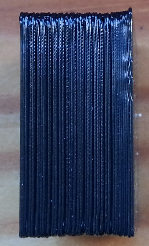
Sorry, only registered users may post in this forum.