Home
>
Reprappers
>
Topic
A new Reprap printer and my blog about it
Posted by drmaestro
|
A new Reprap printer and my blog about it May 11, 2014 08:00PM |
Registered: 9 years ago Posts: 330 |
Hello,
I wanted to introduce myself and my blog about 3d printing. I am very enthousiastic about all things 3D and wanted to buy a printer for a long time. There are a lot of open sourced or commercial models around but I wanted to buy one form a local vendor, as I thought I'd need lots of technical support. I opted in buying a kit instead of a competed model, as I read that's a better way to learn the inner workings of the printer. The vendors I bought the kit from have recently finalized their design and started producing it. I think I have bought their second kit. There wasn't an included manual on how to construct the printer, so I'll be trying to build it with the support I'll recieve from the designers.The problem is that I am complete newbie in this kind of DIY project and I am sure everyone will agree that a 3D printer isn't the ideal kind of project for a first timer. I have decided to document my adeventures (and more probably my misadventures) in a blog. There is very little content in there yet but I am sure it would be beneficial to other newbies, so I'd like to give the link to my blog for those of you who'd be interested:
[www.3dprinterblog.org]
I am open to all kinds of suggestions and critics (and also help!).
Thank you very much....
|
Re: A new Reprap printer and my blog about it May 11, 2014 08:48PM |
Registered: 10 years ago Posts: 903 |
Your confusion on the hardware names between bolts and screws needs a bit of clarification.
This is a machine screw, which is tapped to take a nut (versus a self-tapping wood or sheet metal screw that makes it's own threads as it is screwed in):
http://en.wikipedia.org/wiki/Screw#Differentiation_between_bolt_and_screw
You might find this drawing of various threaded fastener types useful for your explanation:
I applaud the way you are writing the absolute basics first. I have noticed that way too many 3D printer parts suppliers and manufacturers do not have a grasp on the use of washers with fasteners, so there is a need for something this simple.....
This is a machine screw, which is tapped to take a nut (versus a self-tapping wood or sheet metal screw that makes it's own threads as it is screwed in):

http://en.wikipedia.org/wiki/Screw#Differentiation_between_bolt_and_screw
You might find this drawing of various threaded fastener types useful for your explanation:

I applaud the way you are writing the absolute basics first. I have noticed that way too many 3D printer parts suppliers and manufacturers do not have a grasp on the use of washers with fasteners, so there is a need for something this simple.....
|
Re: A new Reprap printer and my blog about it May 12, 2014 12:59PM |
Registered: 9 years ago Posts: 330 |
Hi vreihen,
Thank you for the encouragement. I'll try to document the entire process, which I think is a great learnig experience and maybe a tale of discovery for a newbie.
Also, thanks for the valuable input. The first picture you have posted demonstrates that this is indeed a complicated matter. I have read the wikipedia article on screws, and alos on bolts. [en.wikipedia.org])
This is what I understand, in simple terms, from them:
1) A bolt needs a nut.
2) A screw needs an internally threaded hole and doesn't need a nut.
3) A bolt is generally used for the assembly of two unthreaded components.
4) A screw needs the presence of an internally threaded component in at least one of the components being assembled.
5) A screw needs to be turned to be able to perform its function.
6) A bolt can be turned but also it can be non-rotating and be held in place by turning its nut.
7) These are general rules and rules are meant to be broken
Thanks for the idea on implementing the head types to the blog. Can I use the picture? Is it copyrighted?
I am a little bit confused with the first picture. If this is a screw, what is the function of the nut? Or if I wanted to replace it with a bolt, would there be visible differences between them. Are you calling it a screw, because it can be used with an internally threaded hole? But how can you know that without trying it on the hole? (my last question can be a little bit ambigous; what I meant was would you be able to know this is a screw by just looking at itself or would you need additional information). Can we differentiate a bolt from a screw just by looking at how its threads are shaped (I checked the ISO standart for bolts and for screws and they both have thread angles of 60 degrees. So what is the differnce thread-wise? Are screws meant to be sharper?)
Wow, it is hard to be a complete newbie!
|
Re: A new Reprap printer and my blog about it May 13, 2014 07:26AM |
Registered: 10 years ago Posts: 903 |
I found the images doing a web search, and do not know the copyright status of the source. (I work in academia, and consider it "fair use" in this situation.)
The definitions that you're citing seem to have been written by academics. At least in American English, the things that screw into a threaded engine block to hold the cylinder head on are called head bolts, because they have a hex-shaped head (and don't use a nut).
The definition that I have always used is that if it is turned with a tool by grabbing the outside of the head it is a bolt, and screws are turned by tools that mate against the inside surface of the fastener. So, turn it with a wrench/spanner/socket = bolt, turn it with a screwdriver/torx/allen = screw. Not saying that my definition is correct, and the picture above showing a hex-head cap screw contradicts my statement.
There are two types of threads - self-tapping and machine threads. Machine threads are finer than self-tapping threads. Nuts and pre-threaded holes use machine threads, whereas sheet metal and wood screws use self-tapping threads because their holes are not threaded. I have seen people in the 3D printer world use machine screws as self-tapping screws into un-threaded printed plastic holes, and am guilty of doing it myself. It doesn't have the ideal bite to hold a lot of tension, but for a few grams it is usually fine.
I'd say cite the experts over my definitions. For all that I know, I may have it wrong or there may be no correct answer. However, I still stand behind my statement that we need more documentation on the use of washers in 3D printers.....
The definitions that you're citing seem to have been written by academics.
At least in American English, the things that screw into a threaded engine block to hold the cylinder head on are called head bolts, because they have a hex-shaped head (and don't use a nut).The definition that I have always used is that if it is turned with a tool by grabbing the outside of the head it is a bolt, and screws are turned by tools that mate against the inside surface of the fastener. So, turn it with a wrench/spanner/socket = bolt, turn it with a screwdriver/torx/allen = screw. Not saying that my definition is correct, and the picture above showing a hex-head cap screw contradicts my statement.
There are two types of threads - self-tapping and machine threads. Machine threads are finer than self-tapping threads. Nuts and pre-threaded holes use machine threads, whereas sheet metal and wood screws use self-tapping threads because their holes are not threaded. I have seen people in the 3D printer world use machine screws as self-tapping screws into un-threaded printed plastic holes, and am guilty of doing it myself. It doesn't have the ideal bite to hold a lot of tension, but for a few grams it is usually fine.
I'd say cite the experts over my definitions. For all that I know, I may have it wrong or there may be no correct answer. However, I still stand behind my statement that we need more documentation on the use of washers in 3D printers.....
|
Re: A new Reprap printer and my blog about it May 14, 2014 01:14PM |
Registered: 9 years ago Posts: 330 |
IHi everybody.
I have added the section on how to build the main frame (or the skeleton) of the printer.Here's the link:
[www.3dprinterblog.org]
I have added the section on how to build the main frame (or the skeleton) of the printer.Here's the link:
[www.3dprinterblog.org]
|
Re: A new Reprap printer and my blog about it May 17, 2014 07:10PM |
Registered: 9 years ago Posts: 330 |
|
Re: A new Reprap printer and my blog about it May 21, 2014 07:18PM |
Registered: 9 years ago Posts: 330 |
|
Re: A new Reprap printer and my blog about it May 24, 2014 05:03AM |
Registered: 9 years ago Posts: 330 |
Hello all,
I have added a section on how to assemble the Z rods and Y rods.
Here's the link: http://www.3dprinterblog.org/2014/05/lets-build-it-z-and-y-rods.html
I have added a section on how to assemble the Z rods and Y rods.
Here's the link: http://www.3dprinterblog.org/2014/05/lets-build-it-z-and-y-rods.html
|
Re: A new Reprap printer and my blog about it May 31, 2014 01:47PM |
Registered: 9 years ago Posts: 330 |
Hello,
I have added a blog entry on motors used in the project.
Here's the link: [www.3dprinterblog.org]
I have added a blog entry on motors used in the project.
Here's the link: [www.3dprinterblog.org]
|
Re: A new Reprap printer and my blog about it May 31, 2014 07:58PM |
Registered: 12 years ago Posts: 142 |
|
Re: A new Reprap printer and my blog about it June 08, 2014 12:06AM |
Registered: 9 years ago Posts: 1 |
|
Re: A new Reprap printer and my blog about it June 08, 2014 03:34PM |
Registered: 10 years ago Posts: 439 |
Can you provide a link to the website of the vendor please.
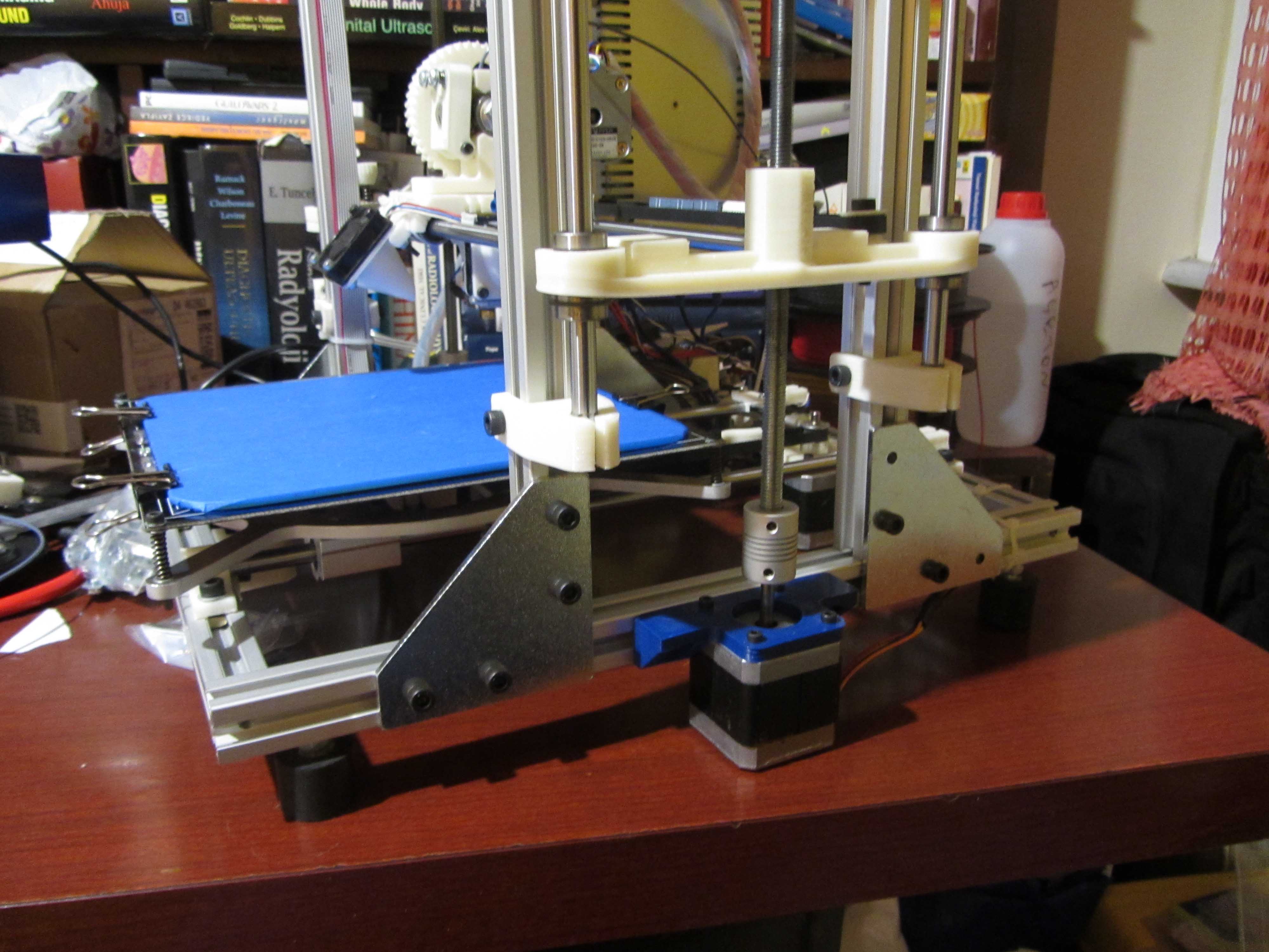
The design looks to me to be inadequately braced to avoid X and Y wobble at the top of tall prints with fast movement of the extruder.
Definitions of screws and bolts vary a lot. Vrheinen seems to be patronizing a little in asserting the rightness of his definitions. The basic definition I was given in school in England 50 years ago is that a bolt has a nut and a screw does not. Google need to add translation between English and American in their choices.
|
Re: A new Reprap printer and my blog about it June 09, 2014 05:57PM |
Registered: 9 years ago Posts: 330 |
Hi,
The web site for the printer is www.sigma3d.org . However the site is mostly in Turkish. You might be able to contact the designers through their e-mail if you want ([email protected]). Or if you want, I can ask them questions or forward your comments.
The web site for the printer is www.sigma3d.org . However the site is mostly in Turkish. You might be able to contact the designers through their e-mail if you want ([email protected]). Or if you want, I can ask them questions or forward your comments.
|
Re: A new Reprap printer and my blog about it June 17, 2014 02:52PM |
Registered: 9 years ago Posts: 330 |
I have uploaded a new blog entry on mounting the Y motor. It also has some information on timing belts.
Here's the link: [www.3dprinterblog.org]
Here's the link: [www.3dprinterblog.org]
|
Re: A new Reprap printer and my blog about it June 18, 2014 03:54PM |
Registered: 9 years ago Posts: 330 |
Quote
Ralph.Hilton
Can you provide a link to the website of the vendor please.
The design looks to me to be inadequately braced to avoid X and Y wobble at the top of tall prints with fast movement of the extruder.
Definitions of screws and bolts vary a lot. Vrheinen seems to be patronizing a little in asserting the rightness of his definitions. The basic definition I was given in school in England 50 years ago is that a bolt has a nut and a screw does not. Google need to add translation between English and American in their choices.
Sir, my experience with the printer so far makes me think you are right about the wobble in the X axis. When the extruder moves, there is a slight wobble even when it is in the lower levels. I think there are two problems causing this: First, the vertical aluminium profiles are held in place by only L shaped metal hinges (one for each vertical profile). And second: The filament spool is heavy and it amplifies the wobble due to inertia. Do you have any suggestions to correct this? I may add additional hinges or may detach the spool. Or do you think it requires a design modification?
Thanks
|
Re: A new Reprap printer and my blog about it June 20, 2014 04:07PM |
Registered: 10 years ago Posts: 439 |
Personally I mounted my filament spool on a wall behind my machine. That way I have more warning if badly wound filament snags.
Also, having a weighty spool mounted at the top of a machine seems to me to increase the probability of mechanical resonance and thus oscillations.
I can't really see from the pictures if there is room - can you fit a piece of aluminium,mdf, dibond or acrylic sheet to the back and/or front of the upper part of the Z profiles? It would extend across the length of the X axis and have a height of 15cm or so. That would brace the top of the machine in the X direction. The principle is shown in the Mendel90 and Prusa links below.
Then it needs bracing in the Y direction. This could be a sheet or rods or extrusion. I would suggest looking at the Mendel90 design and the way the 2 sheets of dibond brace the top of the machine Y axis in a simple inexpensive fashion. [reprap.org]
You could also look at the way this prusa version is stabilized in the Y direction: [reprap.org]
An alternative using a triangularly placed extrusion is shown in this design: [www.thingiverse.com]
Edited 4 time(s). Last edit at 06/20/2014 04:17PM by Ralph.Hilton.
|
Re: A new Reprap printer and my blog about it June 20, 2014 09:11PM |
Registered: 11 years ago Posts: 205 |
A couple of thoughts here.
Nice job on your blog!
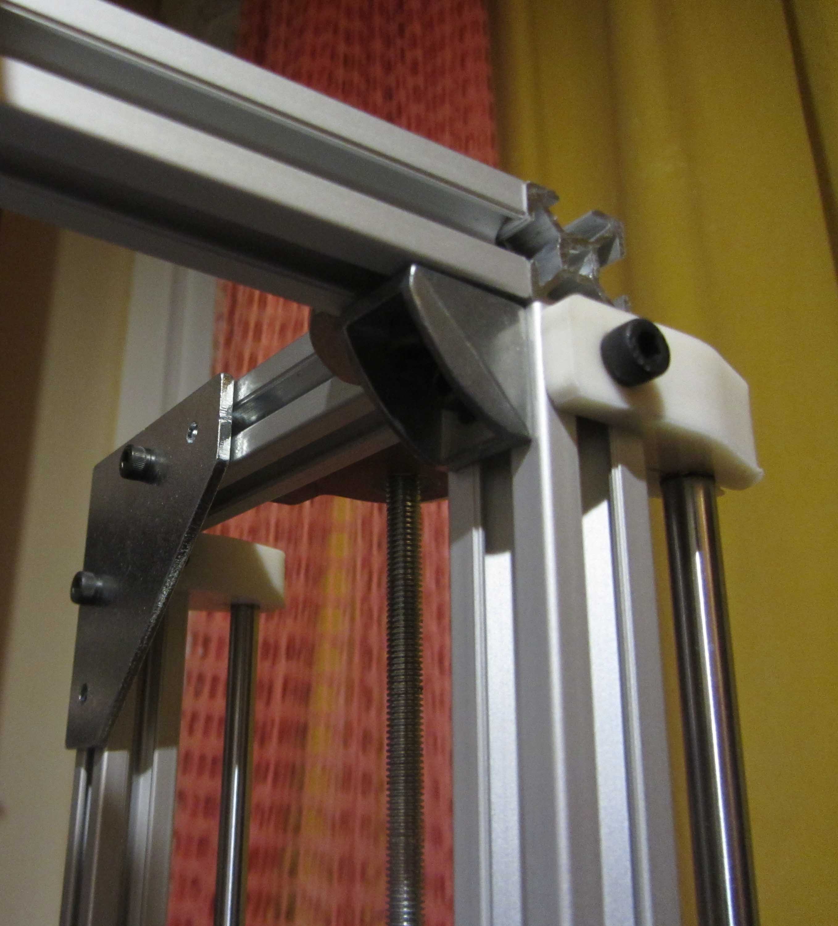
Look for triangles. Do you see any triangles? No? Then your printer frame will not be stiff as the triangle is the only stiff shape in nature. Rectangular frames are notoriously flexible. You need triangles. If you have room for X bracing, which uses only tension you can use just strips of flat metal across corners. If you can only brace in one direction then it must be a stiff member also and you will need to use extrusion for that.
I see you using a tape measure, and I take note of where you measure from. A tape measure is not a good tool for locating rails and squaring a frame for a machine that moves on linear rails. Also you need to make measurements that do not add up your errors. Parallel rails need to be REALLY parallel. So always measure rail to rail not rail to other frames, except for one rail which is the reference to the frame. You need to use a gauge to set frames and rails. Make them from threaded rod, a couple of nuts, a coupling nut and a couple of smooth headed carriage bolts. Adjust the length of your gauge as close as you can to the measured distance. Then use it between the rails and the frames with a feeler gauge to get the rail spacing down to 0.001" or 0.025mm at worse near the mounting points. Do the same with the frame and get it as true as you possible can. Get those 4 Z rails perfect to each other using 3 allthread gauges, left to right, front to back, and diagonally.
Your Z axis is problematic. You have 4 short bushings widely spaced with the screws in the middle and that is very unstable. The short bushings can't keep it from tilting, then can only bind. 3 bushings, two spaced apart on one rail and one as a guide on the other rail would be much better.
Some years ago I was building reciprocating bagging machines. After they were built it usually took two weeks of tuning before they would make good bags. We then built one that I checked every measurement as the mechanics installed parts, and made them fix any that did not match the drawings. When we finally started it, it was in perfect tune 15 minutes later! The mechanics asked how that happened. I told them we simply made it correctly right from the start.
Nice job on your blog!
Look for triangles. Do you see any triangles? No? Then your printer frame will not be stiff as the triangle is the only stiff shape in nature. Rectangular frames are notoriously flexible. You need triangles. If you have room for X bracing, which uses only tension you can use just strips of flat metal across corners. If you can only brace in one direction then it must be a stiff member also and you will need to use extrusion for that.
I see you using a tape measure, and I take note of where you measure from. A tape measure is not a good tool for locating rails and squaring a frame for a machine that moves on linear rails. Also you need to make measurements that do not add up your errors. Parallel rails need to be REALLY parallel. So always measure rail to rail not rail to other frames, except for one rail which is the reference to the frame. You need to use a gauge to set frames and rails. Make them from threaded rod, a couple of nuts, a coupling nut and a couple of smooth headed carriage bolts. Adjust the length of your gauge as close as you can to the measured distance. Then use it between the rails and the frames with a feeler gauge to get the rail spacing down to 0.001" or 0.025mm at worse near the mounting points. Do the same with the frame and get it as true as you possible can. Get those 4 Z rails perfect to each other using 3 allthread gauges, left to right, front to back, and diagonally.
Your Z axis is problematic. You have 4 short bushings widely spaced with the screws in the middle and that is very unstable. The short bushings can't keep it from tilting, then can only bind. 3 bushings, two spaced apart on one rail and one as a guide on the other rail would be much better.
Some years ago I was building reciprocating bagging machines. After they were built it usually took two weeks of tuning before they would make good bags. We then built one that I checked every measurement as the mechanics installed parts, and made them fix any that did not match the drawings. When we finally started it, it was in perfect tune 15 minutes later! The mechanics asked how that happened. I told them we simply made it correctly right from the start.
|
Re: A new Reprap printer and my blog about it July 01, 2014 07:12PM |
Registered: 9 years ago Posts: 330 |
Quote
Ralph.Hilton
Personally I mounted my filament spool on a wall behind my machine. That way I have more warning if badly wound filament snags.
Also, having a weighty spool mounted at the top of a machine seems to me to increase the probability of mechanical resonance and thus oscillations.
I can't really see from the pictures if there is room - can you fit a piece of aluminium,mdf, dibond or acrylic sheet to the back and/or front of the upper part of the Z profiles? It would extend across the length of the X axis and have a height of 15cm or so. That would brace the top of the machine in the X direction. The principle is shown in the Mendel90 and Prusa links below.
Then it needs bracing in the Y direction. This could be a sheet or rods or extrusion. I would suggest looking at the Mendel90 design and the way the 2 sheets of dibond brace the top of the machine Y axis in a simple inexpensive fashion. [reprap.org]
You could also look at the way this prusa version is stabilized in the Y direction: [reprap.org]
An alternative using a triangularly placed extrusion is shown in this design: [www.thingiverse.com]
Quote
garyhlucas
A couple of thoughts here.
Nice job on your blog!
Look for triangles. Do you see any triangles? No? Then your printer frame will not be stiff as the triangle is the only stiff shape in nature. Rectangular frames are notoriously flexible. You need triangles. If you have room for X bracing, which uses only tension you can use just strips of flat metal across corners. If you can only brace in one direction then it must be a stiff member also and you will need to use extrusion for that.
I see you using a tape measure, and I take note of where you measure from. A tape measure is not a good tool for locating rails and squaring a frame for a machine that moves on linear rails. Also you need to make measurements that do not add up your errors. Parallel rails need to be REALLY parallel. So always measure rail to rail not rail to other frames, except for one rail which is the reference to the frame. You need to use a gauge to set frames and rails. Make them from threaded rod, a couple of nuts, a coupling nut and a couple of smooth headed carriage bolts. Adjust the length of your gauge as close as you can to the measured distance. Then use it between the rails and the frames with a feeler gauge to get the rail spacing down to 0.001" or 0.025mm at worse near the mounting points. Do the same with the frame and get it as true as you possible can. Get those 4 Z rails perfect to each other using 3 allthread gauges, left to right, front to back, and diagonally.
Your Z axis is problematic. You have 4 short bushings widely spaced with the screws in the middle and that is very unstable. The short bushings can't keep it from tilting, then can only bind. 3 bushings, two spaced apart on one rail and one as a guide on the other rail would be much better.
Some years ago I was building reciprocating bagging machines. After they were built it usually took two weeks of tuning before they would make good bags. We then built one that I checked every measurement as the mechanics installed parts, and made them fix any that did not match the drawings. When we finally started it, it was in perfect tune 15 minutes later! The mechanics asked how that happened. I told them we simply made it correctly right from the start.
Thank you very much for your comments Ralph.Hilton and garyhlucas.I tried to follow your suggestions and added some triangles to my printer.There are large ones which are flat and also smaller ones which are used on corners. I was able to add 8 of them (I still wanted to add a few more but ran out of T-slot nuts). Now, the printer is much more stable (I'd even dare say rock-solid). I didn't print anything yet so I can't show you the results but I assume it'll have a positive effect on print quality. My Z axis is still wobbling, so I am still far away from perfect prints (I can't determine the reason for this wobble).
|
Re: A new Reprap printer and my blog about it July 07, 2014 08:26AM |
Registered: 9 years ago Posts: 330 |
Hi, I have added a new blog entry. Here's the link: [www.3dprinterblog.org]
Thanks for the comments.....
Thanks for the comments.....
|
Re: A new Reprap printer and my blog about it July 31, 2014 08:47AM |
Registered: 9 years ago Posts: 330 |
Hi,
A new section has been added.
Here's the link: [www.3dprinterblog.org]
Thanks...
Edited 1 time(s). Last edit at 07/31/2014 08:48AM by drmaestro.
A new section has been added.
Here's the link: [www.3dprinterblog.org]
Thanks...
Edited 1 time(s). Last edit at 07/31/2014 08:48AM by drmaestro.
Sorry, only registered users may post in this forum.