Home
>
Reprappers
>
Topic
Stratasys Dimension Retrofit
Posted by I-CNC
|
Stratasys Dimension Retrofit March 07, 2015 07:17PM |
Registered: 9 years ago Posts: 14 |
Hi all,
Let me start by saying I am not particularly electronics friendly, and have limited knowledge of electronics and firmware coding, so this is going to be a significant challenge for me.
That being said.....
Background:
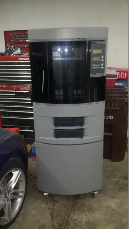
I have acquired a Stratasys Dimension printer and am in the process of attempting to retrofit it with reprap controls. The machine is intact with all of the hardware, however the control boards have been cut out of it and the extruders and hot ends removed. It seemed like an awesome base to start with instead of a scratch build since it has industrial quality slideways and all the steppers, endstops, and fans etc. are already there and installed. Initially I planned to keep just the cabinet with the axis and start from there, but it has the potential to be a very nice machine if I can keep it essentially intact and interface everything with new electronics, so the journey begins......
In factory form the machine includes the following:
Heated chamber - All of the heaters(2) and heat circulation fans (4) are intact, so I would like to retain them. The fans are verified to be 24v, but I'm not sure about the 2 heating elements. I *think* they are 120v. The resistance across the terminals is 36 Ohms, so doing the math, it *seems* like they are 120v, 400 watts each.
Dual filament cartridges and dual extruders - These are mounted below the build chamber. In factory configuration there was one for build material and one for water soluble support material, but I can use them both for build material, I don't know what I'll do until I get it operational.
The filament cartridges have a feed mechanism that engages to advance the filament to the extruder. The drive mechanism is engaged with a solenoid to bring the pinch rollers in contact with the filament. I believe this is only done when the cartridge is changed and the filament is being advanced to the extruder. Once the filament is engaged by the extruder these disengage and the extruder takes control of the filament.
A door interlock to keep the door from opening if the chamber is at print temperature.
Solenoid activated latches on the cartridges to hold them in place. When you push one of the cartridges in, it unlatches. When it is reinstalled a solenoid is energized momentarily to engage the latch to hold the cartridge in under spring tension, after which the solenoid can be de-energized.
The chamber temperature is monitored with a thermocouple.
My (probably poorly hatched) plan:
My basic plan was to control the print/ heat functions with a reprap control board, and use a separate Arduino to control the miscellaneous functions such as the cartridge latches, door interlock, filament advance, etc. My thought was that the separate microcontroller would be easier for me to program outside of the print controller, and would also insure that there were enough I/O pins available to control these functions.
I have purchased a Duet + Duex4 Control board bundle, but think I may be in over my head when it comes to interfacing it with the existing hardware. Although this will probably seem very rudimentary to those in the electronics/ firmware club, I am at this point completely overwhelmed by the firmware mods that will be necessary, and to a slightly lesser degree, the electronics knowledge required. At this point I am very seriously considering shelving the Duet, and getting a Smoothieboard, because from what I have discovered so far in my research, the Smoothieboard will be much easier to implement. The one caveat here is that one of the pressing reasons to go with the Duet was the availability of the near plug and play PanelDue, which is very important to me since this is a relatively large machine, and stand alone printing is very important (and because the TFT screen is freakin' awesome and I WANT IT!!!
The biggest challenges I see with keeping the Duet:
The motors are NEMA 23, listed as 3a/ 6a, so the onboard drivers aren't going to be up to the task, and since it's an industrial machine, the axis a pretty heavy, so limiting the current will probably not get the motion speed/ smoothness/ accuracy needed. The problem here is that I have not a clue how to interface bigger drivers. The Smoothieboard, on the other hand, has all of the step, direction, enable, and ground pins broken out on the board - easy peasy. I'm sure that these signals are available through an expansion header somewhere on Duet or Duex4, but between my lack of electronics skills and the documentation being on the weak side for Duet, I'm at a loss....
The machine is set up for both max and min endstops, normally closed. I know I don't need them both, but I would sorta like to retain them all. I also haven't figured out yet if Duet expects normally open or normally closed, and where to invert them in the firmware if they aren't correct. Smoothieboard has inputs of both max and min endstops, and it is well documented how and where to invert them in the firmware.
There are only 2 thermistor inputs on the main Duet board.. There are additional ones on the Duex4, but I think there is a noise issue if they are used. There is a workaround (thanks dc42)! I need a minimum of 3 inputs. Smoothieboard has 4 inputs.
For either board, I have to figure out how to control the chamber heaters. I was thinking I could use an SSR capable of switching 120v, controlled by the onboard heated bed mosfet, but I'm not sure if this will work.
I would like to retain the thermocouple. I have not a clue how to deal with the firmware issues that may need to be addressed, if there are any. It looks like I can get a board to interface the thermocouple, I just have no clue how to implement it into the firmware. I'm not sure if I *need* to have the thermocouple, but I would like the capability to print nylon, and possibly polycarbonate. I don't know if a thermistor will work reliably at the elevated temperatures required or not.
If I switch to Smoothieboard I would like to implement the PanelDue, which isn't supported by Smoothieboard.
So..... what's everyone's suggestion on how to proceed???? HELP ME!!!
PS - Sorry to type a novel.... There is just a lot of information to get out, and without all of it, understanding the big picture is more difficult.
Edited 1 time(s). Last edit at 03/07/2015 07:43PM by I-CNC.
Let me start by saying I am not particularly electronics friendly, and have limited knowledge of electronics and firmware coding, so this is going to be a significant challenge for me.
That being said.....
Background:
I have acquired a Stratasys Dimension printer and am in the process of attempting to retrofit it with reprap controls. The machine is intact with all of the hardware, however the control boards have been cut out of it and the extruders and hot ends removed. It seemed like an awesome base to start with instead of a scratch build since it has industrial quality slideways and all the steppers, endstops, and fans etc. are already there and installed. Initially I planned to keep just the cabinet with the axis and start from there, but it has the potential to be a very nice machine if I can keep it essentially intact and interface everything with new electronics, so the journey begins......
In factory form the machine includes the following:
Heated chamber - All of the heaters(2) and heat circulation fans (4) are intact, so I would like to retain them. The fans are verified to be 24v, but I'm not sure about the 2 heating elements. I *think* they are 120v. The resistance across the terminals is 36 Ohms, so doing the math, it *seems* like they are 120v, 400 watts each.
Dual filament cartridges and dual extruders - These are mounted below the build chamber. In factory configuration there was one for build material and one for water soluble support material, but I can use them both for build material, I don't know what I'll do until I get it operational.
The filament cartridges have a feed mechanism that engages to advance the filament to the extruder. The drive mechanism is engaged with a solenoid to bring the pinch rollers in contact with the filament. I believe this is only done when the cartridge is changed and the filament is being advanced to the extruder. Once the filament is engaged by the extruder these disengage and the extruder takes control of the filament.
A door interlock to keep the door from opening if the chamber is at print temperature.
Solenoid activated latches on the cartridges to hold them in place. When you push one of the cartridges in, it unlatches. When it is reinstalled a solenoid is energized momentarily to engage the latch to hold the cartridge in under spring tension, after which the solenoid can be de-energized.
The chamber temperature is monitored with a thermocouple.
My (probably poorly hatched) plan:
My basic plan was to control the print/ heat functions with a reprap control board, and use a separate Arduino to control the miscellaneous functions such as the cartridge latches, door interlock, filament advance, etc. My thought was that the separate microcontroller would be easier for me to program outside of the print controller, and would also insure that there were enough I/O pins available to control these functions.
I have purchased a Duet + Duex4 Control board bundle, but think I may be in over my head when it comes to interfacing it with the existing hardware. Although this will probably seem very rudimentary to those in the electronics/ firmware club, I am at this point completely overwhelmed by the firmware mods that will be necessary, and to a slightly lesser degree, the electronics knowledge required. At this point I am very seriously considering shelving the Duet, and getting a Smoothieboard, because from what I have discovered so far in my research, the Smoothieboard will be much easier to implement. The one caveat here is that one of the pressing reasons to go with the Duet was the availability of the near plug and play PanelDue, which is very important to me since this is a relatively large machine, and stand alone printing is very important (and because the TFT screen is freakin' awesome and I WANT IT!!!
The biggest challenges I see with keeping the Duet:
The motors are NEMA 23, listed as 3a/ 6a, so the onboard drivers aren't going to be up to the task, and since it's an industrial machine, the axis a pretty heavy, so limiting the current will probably not get the motion speed/ smoothness/ accuracy needed. The problem here is that I have not a clue how to interface bigger drivers. The Smoothieboard, on the other hand, has all of the step, direction, enable, and ground pins broken out on the board - easy peasy. I'm sure that these signals are available through an expansion header somewhere on Duet or Duex4, but between my lack of electronics skills and the documentation being on the weak side for Duet, I'm at a loss....
The machine is set up for both max and min endstops, normally closed. I know I don't need them both, but I would sorta like to retain them all. I also haven't figured out yet if Duet expects normally open or normally closed, and where to invert them in the firmware if they aren't correct. Smoothieboard has inputs of both max and min endstops, and it is well documented how and where to invert them in the firmware.
There are only 2 thermistor inputs on the main Duet board.. There are additional ones on the Duex4, but I think there is a noise issue if they are used. There is a workaround (thanks dc42)! I need a minimum of 3 inputs. Smoothieboard has 4 inputs.
For either board, I have to figure out how to control the chamber heaters. I was thinking I could use an SSR capable of switching 120v, controlled by the onboard heated bed mosfet, but I'm not sure if this will work.
I would like to retain the thermocouple. I have not a clue how to deal with the firmware issues that may need to be addressed, if there are any. It looks like I can get a board to interface the thermocouple, I just have no clue how to implement it into the firmware. I'm not sure if I *need* to have the thermocouple, but I would like the capability to print nylon, and possibly polycarbonate. I don't know if a thermistor will work reliably at the elevated temperatures required or not.
If I switch to Smoothieboard I would like to implement the PanelDue, which isn't supported by Smoothieboard.
So..... what's everyone's suggestion on how to proceed???? HELP ME!!!
PS - Sorry to type a novel.... There is just a lot of information to get out, and without all of it, understanding the big picture is more difficult.
Edited 1 time(s). Last edit at 03/07/2015 07:43PM by I-CNC.
|
Re: Stratasys Dimension Retrofit March 07, 2015 07:32PM |
Registered: 9 years ago Posts: 14 |
|
Re: Stratasys Dimension Retrofit March 08, 2015 06:15AM |
Registered: 10 years ago Posts: 14,672 |
It's a difficult choice. The ideal board for you might be the low-cost 32-bit controller board I am working on. It supports plug-in driver modules like RAMPS, so you can easily connect it to external stepper drivers instead. It supports 2 extruders, 3 heaters and 3 thermistors. It will run RepRapFirmware, so it will support PanelDue. But I don't expect to have prototypes for about a month.
I am considering adding thermocouple support to RepRapFirmware. As I don't have any use for a thermocouple myself, I would prefer to be sponsored for doing this. My preference would be to support a MAX31855-based board such as this [www.ebay.co.uk]. It would connect to the expansion connector, so it would not take up any of the thermistor inputs.
The Duet does not bring out the step and direction pins for the 4 stepper drivers on the main board. So you would need to modify the firmware to reassign the pins to the expansion connector. This is quite easy to do once you have the firmware build environment set up, because the pin numbers are all defined as constants in one file (Platform.h).
If you need 3 thermistor inputs, then to avoid the noise issue on the DueX4, the simplest approach is to use the two Duet thermistor inputs for the hot ends, and one on the DueX4 for the heated bed. If your printer doesn't have a heated bed but just an enclosure heater, then you could use the one on the X4 for the enclosure thermistor instead. However, you mentioned a thermocouple. Does this replace one of the thermistors? If so, then I don't think you need to use the DueX4 at all. Just drive the stepper motors from the Duet expansion connector, the second hot end heater from the heated bed connector, and the heated chamber SSR direct from an expansion connector pin. The thermocouple board will connect to the expansion connector too.
btw there is now a Duet shield, which does most of what the DueX4 does but sits on top of the Duet and doesn't have the noise issue on the thermistor inputs. It supports 2 extra extruders and heaters, rather than the 4 that the X4 supports.
If you choose a Smoothieboard instead, then I guess you need to persuade the maintainers of Smoothieware to add support for PanelDue.
Hope this helps!
Large delta printer [miscsolutions.wordpress.com], E3D tool changer, Robotdigg SCARA printer, Crane Quad and Ormerod
Disclosure: I design Duet electronics and work on RepRapFirmware, [duet3d.com].
|
Re: Stratasys Dimension Retrofit March 08, 2015 11:57AM |
Registered: 9 years ago Posts: 14 |
This does help - a lot!! Thank you!
Some questions:
This could be a possibility. Since this new board will run reprapfirmware, I assume it would have all the capabilities of the Duet?? I really want to try to figure out the Duet, since I've already bought it.
That being said, there are obviously numerous things I would need to figure out to make this work for my application, but maybe by addressing one issue at a time I can figure out most of this with some help.
First problem - Connecting larger stepper drivers.
Solution - remap pin definitions to the expansion header on the Duex4 where they can then be input to the offboard drivers.
I had looked at Platform.h before, found the pin definitions for the step, direction, and enable pins, got confused and frustrated and gave up because I couldn't make heads or tails of it. I'll attempt to explain my confusion.
The line I interpret to define the step pins in the firmware:
#define STEP_PINS {14, 25, 5, X2, 41, 39, X4, 49}
In my simple mind, I would assume this statement to define the processor pin #s that will output the step signals that are then input into the stepper driver. I am assuming (possibly incorrectly) that this means this:
X step = pin 14
Y step = pin 25
Z step = pin 5
E0 = pin X2
E1 = pin 41
E2 = pin 39
E3 = pin X4
E4 = pin 49
However, when comparing this to the processor schematic, it shows the following:
X step = pin 17 on processor
Y Step = pin 13 on processor
Z Step = pin 136 on processor
E0 Step = pin 23 on processor
etc....
So why wouldn't the current firmware line (assuming we were just assigning for X,Y,Z and E0) look like this:
#define STEP_PINS {17, 13, 136, 23}
Also, what do the values X2 and X4 relate to?? Obviously not processor pin #s
Where am I going wrong in my interpretation??
Thanks for any help you can give!!!
Edited 1 time(s). Last edit at 03/08/2015 02:10PM by I-CNC.
Some questions:
Quote
dc42
The ideal board for you might be the low-cost 32-bit controller board I am working on.
This could be a possibility. Since this new board will run reprapfirmware, I assume it would have all the capabilities of the Duet?? I really want to try to figure out the Duet, since I've already bought it.
That being said, there are obviously numerous things I would need to figure out to make this work for my application, but maybe by addressing one issue at a time I can figure out most of this with some help.
First problem - Connecting larger stepper drivers.
Solution - remap pin definitions to the expansion header on the Duex4 where they can then be input to the offboard drivers.
I had looked at Platform.h before, found the pin definitions for the step, direction, and enable pins, got confused and frustrated and gave up because I couldn't make heads or tails of it. I'll attempt to explain my confusion.
The line I interpret to define the step pins in the firmware:
#define STEP_PINS {14, 25, 5, X2, 41, 39, X4, 49}
In my simple mind, I would assume this statement to define the processor pin #s that will output the step signals that are then input into the stepper driver. I am assuming (possibly incorrectly) that this means this:
X step = pin 14
Y step = pin 25
Z step = pin 5
E0 = pin X2
E1 = pin 41
E2 = pin 39
E3 = pin X4
E4 = pin 49
However, when comparing this to the processor schematic, it shows the following:
X step = pin 17 on processor
Y Step = pin 13 on processor
Z Step = pin 136 on processor
E0 Step = pin 23 on processor
etc....
So why wouldn't the current firmware line (assuming we were just assigning for X,Y,Z and E0) look like this:
#define STEP_PINS {17, 13, 136, 23}
Also, what do the values X2 and X4 relate to?? Obviously not processor pin #s
Where am I going wrong in my interpretation??
Thanks for any help you can give!!!
Edited 1 time(s). Last edit at 03/08/2015 02:10PM by I-CNC.
|
Re: Stratasys Dimension Retrofit March 08, 2015 12:37PM |
Registered: 10 years ago Posts: 14,672 |
The Duet is in some ways similar to the Arduino Due, and the firmware uses parts of the Arduino Due core to access the I/O ports. So the pin numbers are Arduino Due pin numbers. The mapping to processor pin numbers is at [arduino.cc].
The pin numbers starting with X refer to processor pins that the Arduino Due does not make available. The mapping to processor ports for those pins is defined by the table in file SamNonDuePin in the Libraries folder.
Large delta printer [miscsolutions.wordpress.com], E3D tool changer, Robotdigg SCARA printer, Crane Quad and Ormerod
Disclosure: I design Duet electronics and work on RepRapFirmware, [duet3d.com].
|
Re: Stratasys Dimension Retrofit March 08, 2015 01:27PM |
Registered: 9 years ago Posts: 14 |
THANK YOU!!!!! That explains why I was so confused. I will look at all this and I should be able to figure out pin assignments based on this. This leaves me 3 questions:
1) Correct me if I'm wrong, I will need 9 pins mapped to the expansion header on Duex4 to breakout the required signals for the X, Y, and Z axis and there are enough available.
2) Would another option be to re-map the Duet to make it an all extruder board and then re-map the pins from the expansion header that were used for the extra extruder signals to run the external axis steppers, and disconnect just those pins from the Duex4, leaving the rest intact? This would preserve the 9 pins on the Duex4 for future use?? If I did this, I could switch the endstop pins with the thermistor inputs between the two to avoid the noise on Duex4, or am I not thinking this through enough??
3) Can I map to any pins on the expansion header that I choose, provided they are output by the processor? Of course I would want to avoid the ones used for PanelDue (I'm assuming I can find documentation somewhere specifying which pins PanelDue uses). Are there any others that I would specifically want to avoid??
Edited 2 time(s). Last edit at 03/08/2015 01:32PM by I-CNC.
|
Re: Stratasys Dimension Retrofit March 08, 2015 02:31PM |
Registered: 10 years ago Posts: 14,672 |
1 & 2. Do you really need to use the X4? See my previous reply. If you do, then I suggest you use 9 of the 12 pins on the expansion connector that feed the DueX4 stepper motors drivers for your 3 external stepper motor drivers. There is no need to disconnect them from the X4, the Duet can drive both drivers in parallel. Then use the Duet outputs to drive the extruder steppers as you suggested, if you think they are powerful enough for the extruder motors. So you don't need to allocate any expansion connector pins for the axis drivers.
To get at all the wires in the expansion connector, you could clamp an IDC ribbon cable socket on to the middle of the connecting cable.
3. You should avoid the 2 expansion pins used by the Z probe. Also keep some SPI pins free on the expansion connector, so that we can use hardware SPI to connect the thermocouple board(s). PanelDue uses the UTxD and URxD pins, and also takes +5V and Gnd.
Large delta printer [miscsolutions.wordpress.com], E3D tool changer, Robotdigg SCARA printer, Crane Quad and Ormerod
Disclosure: I design Duet electronics and work on RepRapFirmware, [duet3d.com].
|
Re: Stratasys Dimension Retrofit March 08, 2015 03:48PM |
Registered: 9 years ago Posts: 14 |
Ah, nice catch..... Yes, one of the thermistors would be replaced by the thermocouple, so I could eliminate the X4 board.
The extruders and hotends will be some version of reprap units, so driving them from the on board drivers shouldn't be a problem.
So based on that scenario, the plan of action required to complete this portion of the project would look like this:
A ) Eliminate the X4
B ) Re-define the Duet to run the 2 extruders from it. Abandon the other 2 on board stepper drivers.
C ) Redefine the pins on the expansion that are currently used for 3 of the extruder stepper drivers to provide signal to the external axis stepper drivers.
Questions:
1 ) Doing the above would require the thermocouple to used? Or could I re-define the pins currently used by the axis endstops to be thermistor inputs, and move the axis endstops to the pins on the expansion formerly used for the thermistor inputs?
2 ) It looks like there are 5 SPI pins on the expansion (pin #s 26 - 30 on the Duet header schematic) - Am I reading this correctly?
|
Re: Stratasys Dimension Retrofit March 08, 2015 03:53PM |
Registered: 9 years ago Posts: 14 |
Quote
I-CNC
Or could I re-define the pins currently used by the axis endstops to be thermistor inputs, and move the axis endstops to the pins on the expansion formerly used for the thermistor inputs?
Oops, I missed the fact that this won't work since the thermistor requires 2 inputs but the endstop only has 1 .
|
Re: Stratasys Dimension Retrofit March 08, 2015 04:37PM |
Registered: 13 years ago Posts: 44 |
|
Re: Stratasys Dimension Retrofit March 08, 2015 05:03PM |
Registered: 10 years ago Posts: 14,672 |
Quote
I-CNC
Oops, I missed the fact that this won't work since the thermistor requires 2 inputs but the endstop only has 1 .
The thermistor requires one input than can feed the ADC on the SAM3X8E processor, and ground. The ground connection should preferably be analog ground for accurate and noise-free results. Unfortunately, analog ground is not available on the expansion connector - hence the noise issue on the DueX4 thermistor inputs. The Duet Shield gets round this by picking up analog ground from one of the thermistor connectors on the Duet. You could do the same. You would need to add a 4.7K resistor to +3.3V if you want to use one of the expansion connector pins as an extra thermistor input.
Large delta printer [miscsolutions.wordpress.com], E3D tool changer, Robotdigg SCARA printer, Crane Quad and Ormerod
Disclosure: I design Duet electronics and work on RepRapFirmware, [duet3d.com].
|
Re: Stratasys Dimension Retrofit March 08, 2015 08:42PM |
Registered: 9 years ago Posts: 14 |
Quote
I-CNC
Ah, nice catch..... Yes, one of the thermistors would be replaced by the thermocouple, so I could eliminate the X4 board.
The extruders and hotends will be some version of reprap units, so driving them from the on board drivers shouldn't be a problem.
So based on that scenario, the plan of action required to complete this portion of the project would look like this:
A ) Eliminate the X4
B ) Re-define the Duet to run the 2 extruders from it. Abandon the other 2 on board stepper drivers.
C ) Redefine the pins on the expansion that are currently used for 3 of the extruder stepper drivers to provide signal to the external axis stepper drivers.
Questions:
1 ) Doing the above would require the thermocouple to used? Or could I re-define the pins currently used by the axis endstops to be thermistor inputs, and move the axis endstops to the pins on the expansion formerly used for the thermistor inputs?
2 ) It looks like there are 5 SPI pins on the expansion (pin #s 26 - 30 on the Duet header schematic) - Am I reading this correctly?
I think this post was probably over looked since it was up a few. I apologize if you have already seen it. Any insight to the questions??
Thanks again for all the help!!! This is starting to look possible!!
|
Re: Stratasys Dimension Retrofit March 09, 2015 04:49AM |
Registered: 10 years ago Posts: 14,672 |
I answered your question on how to add an extra thermistor without using the X4 already.
The Duet expansion connector does have those 5 SPI pins. You would connect thermocouple boards to the SPCK0 and MISO pins, plus one of the NPCS pins per thermocouple board.
Large delta printer [miscsolutions.wordpress.com], E3D tool changer, Robotdigg SCARA printer, Crane Quad and Ormerod
Disclosure: I design Duet electronics and work on RepRapFirmware, [duet3d.com].
|
Re: Stratasys Dimension Retrofit March 09, 2015 08:00PM |
Registered: 9 years ago Posts: 14 |
Thanks so much, I'm starting to get it 
I'm still confused on the pins that are Defined in the SamNonDuePin file.
In Platfom.h we have this line:
#define ENABLE_PINS {29, 27, X1, X0, 37, X8, 50, 47}
And when I look up X1 in the SamNonDuePin folder I find this:
static const uint8_t X1 = 101;
I can't figure out what the 101 relates to. I thought it was the processor pin, but when I look up pin 101 on the Duet schematic, instead of showing it is used for Z Enable as I would expect, it says PC19/PWMH5, and Z Enable is shown as pin # 138 on the schematic.
Thanks again!
|
Re: Stratasys Dimension Retrofit March 10, 2015 04:48AM |
Registered: 10 years ago Posts: 14,672 |
The mapping for the X pins is defined in the table at the top of file SamNonDuePin.cpp within the Libraries folder. The table starts from pin 100. The second line of that table reads:
So that tells you that X1 is port PC27 on the chip.
Large delta printer [miscsolutions.wordpress.com], E3D tool changer, Robotdigg SCARA printer, Crane Quad and Ormerod
Disclosure: I design Duet electronics and work on RepRapFirmware, [duet3d.com].
{ PIOC, PIO_PC27, ID_PIOC, PIO_OUTPUT_0, PIO_DEFAULT, PIN_ATTR_DIGITAL, NO_ADC, NO_ADC, NOT_ON_PWM, NOT_ON_TIMER }, // PIN X1
So that tells you that X1 is port PC27 on the chip.
Large delta printer [miscsolutions.wordpress.com], E3D tool changer, Robotdigg SCARA printer, Crane Quad and Ormerod
Disclosure: I design Duet electronics and work on RepRapFirmware, [duet3d.com].
|
Re: Stratasys Dimension Retrofit March 10, 2015 04:46PM |
Registered: 9 years ago Posts: 14 |
OK, I think I have most of what I need to feel comfortable doing this.
My Plan is to basically invert the signals for the steppers as follows:
Move E1 to what was X, Move X to what was E1
E2 to Y, Then Y to E2
E3 to Z, Then Z to E3
This would use the 4 on board drivers on Duet for 4 extruders, and move X, Y, and Z to the expansion header, and would make sure all pins that were carrying Step, Direction, and Enable signals are still carrying them (just on different axis/ extruders).
Soooo...... Last barrage of question on the steppers (I hope):
1) Do I change the platform.h file, or platform.cpp, or both? Do I just have to change it on the 3 lines that define the step, direction, and enable pins, or are there other places I need to make changes as well??
2) Leaving all pins that were assigned as stepper signals, just reassigned, would insure that there wouldn't need to be any changes to how the pins are configured, since they are still doing what they were doing, just for different extruders and axis. Is this correct??
3) I am assuming that the order the pins are defined are like so:
#define STEP_PINS {14(X), 25(Y), 5(Z), X2(E0), 41(E1), 39(E2), X4(E3), 49(E4)}
Is this correct??
4) Is the following line the place I change the direction of the motors if the axis move backwards from what is intended??
#define DIRECTIONS {BACKWARDS, FORWARDS, FORWARDS, FORWARDS, FORWARDS, FORWARDS, FORWARDS, FORWARDS}
5) Looking at the following line, It looks like the Z axis is disabled, or am I reading it wrong??
#define DISABLE_DRIVES {false, false, true, false, false, false, false, false}
That's it for now...
Edited 1 time(s). Last edit at 03/10/2015 04:47PM by I-CNC.
|
Re: Stratasys Dimension Retrofit March 11, 2015 05:00AM |
Registered: 10 years ago Posts: 14,672 |
Quote
I-CNC
1) Do I change the platform.h file, or platform.cpp, or both?
Just the 3 lines in Platform.h.
Quote
I-CNC
2) Leaving all pins that were assigned as stepper signals, just reassigned, would insure that there wouldn't need to be any changes to how the pins are configured, since they are still doing what they were doing, just for different extruders and axis. Is this correct??
Yes..
Quote
I-CNC
3) I am assuming that the order the pins are defined are like so:
#define STEP_PINS {14(X), 25(Y), 5(Z), X2(E0), 41(E1), 39(E2), X4(E3), 49(E4)}
Is this correct??
Yes.
Quote
I-CNC
4) Is the following line the place I change the direction of the motors if the axis move backwards from what is intended??
#define DIRECTIONS {BACKWARDS, FORWARDS, FORWARDS, FORWARDS, FORWARDS, FORWARDS, FORWARDS, FORWARDS}
You can do that, or you can adjust the directions using M569 commands in config.g instead.
Quote
I-CNC
5) Looking at the following line, It looks like the Z axis is disabled, or am I reading it wrong??
#define DISABLE_DRIVES {false, false, true, false, false, false, false, false}
That is supposed to define which drives get turned off if the axis becomes idle, but that isn't implemented yet either in the official RepRapFirmware or in my fork. So that line currently does nothing. When I get round to doing something like this, instead of disabling idle drives I intend to reduce the current to about 30% of normal instead.
Edited 1 time(s). Last edit at 03/11/2015 05:57AM by dc42.
Large delta printer [miscsolutions.wordpress.com], E3D tool changer, Robotdigg SCARA printer, Crane Quad and Ormerod
Disclosure: I design Duet electronics and work on RepRapFirmware, [duet3d.com].
|
Re: Stratasys Dimension Retrofit March 11, 2015 09:06PM |
Registered: 9 years ago Posts: 14 |
|
Re: Stratasys Dimension Retrofit March 16, 2015 03:11AM |
Registered: 9 years ago Posts: 14 |
|
Re: Stratasys Dimension Retrofit March 16, 2015 05:07AM |
Registered: 10 years ago Posts: 14,672 |
My firmware fork can be configured for either NC or NO endstops. The usual choice is NC, which means you need to select S1 (active high) in the M574 command.
Large delta printer [miscsolutions.wordpress.com], E3D tool changer, Robotdigg SCARA printer, Crane Quad and Ormerod
Disclosure: I design Duet electronics and work on RepRapFirmware, [duet3d.com].
Large delta printer [miscsolutions.wordpress.com], E3D tool changer, Robotdigg SCARA printer, Crane Quad and Ormerod
Disclosure: I design Duet electronics and work on RepRapFirmware, [duet3d.com].
Sorry, only registered users may post in this forum.