Home
>
Reprappers
>
Topic
Build plate warpage
Posted by elwood127
|
Build plate warpage August 12, 2015 06:48PM |
Registered: 9 years ago Posts: 705 |
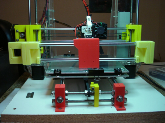
Our Digital Dentist called it. I installed an 1/8" build plate on my I3 that uses (4) adjustment screws. DD had pointed out that a (3) point adjusting system was better because it eliminated warping. Well, I set level today and saw that after going from corner to corner with my copy paper gauge it was tight in the middle of the plate. Thinking that it must be high in the middle I flipped the plate over and readjusted level. It was high in the middle again. Who would think that such little tension would cause a roughly .003 deflection. I even backed out the adjustment screws to barely snug and it still warped. Tomorrow I'm picking up my 1/4" 6061 mill plate and will be adapting it to the (3) point leveling system as on DD's awesome printer (Megamax?). Thanks DD. Nice call.
|
Re: Build plate warpage August 12, 2015 10:48PM |
Registered: 11 years ago Posts: 5,780 |
|
Re: Build plate warpage August 13, 2015 02:16AM |
Registered: 10 years ago Posts: 14,672 |
If it's tight in the middle whichever side of the plate you use, then it is probably the print head being lower in the middle, not the plate bulging in the middle.
Large delta printer [miscsolutions.wordpress.com], E3D tool changer, Robotdigg SCARA printer, Crane Quad and Ormerod
Disclosure: I design Duet electronics and work on RepRapFirmware, [duet3d.com].
Large delta printer [miscsolutions.wordpress.com], E3D tool changer, Robotdigg SCARA printer, Crane Quad and Ormerod
Disclosure: I design Duet electronics and work on RepRapFirmware, [duet3d.com].
|
Re: Build plate warpage August 13, 2015 01:39PM |
Registered: 10 years ago Posts: 466 |
I am interested in the results. I have the exact same problem and have thought about going to 3 point bed leveling. but dc42 brings up a good point, it may be flex in the rods and not a bow in the bed.
Now I'm thinking about some sort of counterweight to attach to the head to test that theory, but how much weight? need to do a little research on that one.
Now I'm thinking about some sort of counterweight to attach to the head to test that theory, but how much weight? need to do a little research on that one.
|
Re: Build plate warpage August 13, 2015 02:44PM |
Registered: 11 years ago Posts: 5,780 |
The ideal weight would need to be a little more than the weight of the extruder carriage due to losses in the pulley connecting the weight to the extruder carriage, but be careful. If you unload the X axis guide rails the Z axis screws, normally loaded by gravity, may not behave well and could bind or cause poor print surface quality. Next you'll have to figure out how to use a counterweight on the Y axis rails, because they are flexing too.
Instead of messing around with Rube Goldbergesque mechanisms to compensate for all this rail flexing, why not just build the thing right and reduce the flexing to inconsequential levels by using fully supported rails or linear guides?
Ultra MegaMax Dominator 3D printer: [drmrehorst.blogspot.com]
Instead of messing around with Rube Goldbergesque mechanisms to compensate for all this rail flexing, why not just build the thing right and reduce the flexing to inconsequential levels by using fully supported rails or linear guides?
Ultra MegaMax Dominator 3D printer: [drmrehorst.blogspot.com]
|
Re: Build plate warpage August 13, 2015 03:01PM |
Registered: 10 years ago Posts: 466 |
Quote
the_digital_dentist
The ideal weight would need to be a little more than the weight of the extruder carriage due to losses in the pulley connecting the weight to the extruder carriage, but be careful. If you unload the X axis guide rails the Z axis screws, normally loaded by gravity, may not behave well and could bind or cause poor print surface quality. Next you'll have to figure out how to use a counterweight on the Y axis rails, because they are flexing too.
Instead of messing around with Rube Goldbergesque mechanisms to compensate for all this rail flexing, why not just build the thing right and reduce the flexing to inconsequential levels by using fully supported rails or linear guides?
wasn't going to be a permanent thing. just a test to see which of my 2 planes were out of whack. then yes..I would build a better mousetrap..
|
Re: Build plate warpage August 13, 2015 05:01PM |
Registered: 9 years ago Posts: 705 |
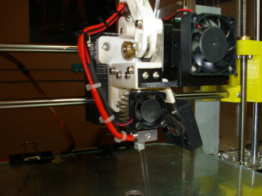
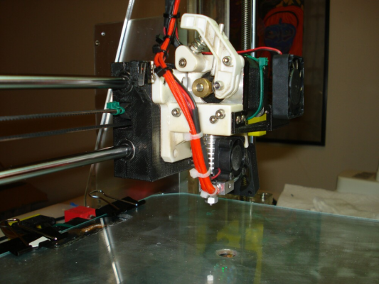
My goal until the build of a new sturdy printer is to get the absolute max out of my cheezy acrylic printer. I have pondered whether the added weight of extruders and fans was causing a droop in the x rods so I decided to change my x rods to 10mm. I've already printed new x carriage parts. Hopefully my 10mm rods show up soon. Considering the design flaws included in these kits I'm getting some pretty darn impressive prints. But, I want more. Locking down the feet made a massive difference in stability. Y rods and acrylic frame for the most part don't flex anymore. I picked up my .250 mill plate today and will be printing the three point leveling attachment pieces tonight via DD's approach. At the very least I want to be able to help all of us that went cheap to get the best these machines can offer without replacing them. When I'm done I'm going to post all of the inhanced pieces that can be made by everyone. These are already available. (https://www.thingiverse.com/elwood127/about) I shall not be denied. At worst it will be an exercise in learning what my next build should incorporate. Thanks for the input.
|
Re: Build plate warpage August 14, 2015 01:02AM |
Registered: 9 years ago Posts: 483 |
Before you attach the new plate to the machine, you could use it to determine if the old plate is the problem or if the rails are the problem. Put some bluing on the plate and rub it against the old plate (leave the old plate installed on the machine). You can use Prussian blue artists paint if you don't have bluing. High and low spots will be quite visible.
|
Re: Build plate warpage August 15, 2015 12:42PM |
Registered: 9 years ago Posts: 100 |
I agree with DC42, if your X carriage is suspended on round steel bars then it will have a very slight sag in the middle, most people overlook this and assume the print bed is not flat (see my last Blog post for more on that, I've included a spreadsheet that will calculate the theoretical deflection).
|
Re: Build plate warpage August 15, 2015 02:31PM |
Registered: 11 years ago Posts: 5,780 |
If you want to get real fancy, you can calculate the sag in the X and Y axes and apply some extra weight to one or the other so they sag equal amounts and thereby cancel the effect of the sagging. You might want to ensure that the guide rail supports and the bearings on the carriages are equally spaced in both axes, then, with equal masses, they will sag identically. You may need to slow the print speed a little to accommodate the extra weight on the extruder carriage. Next, modify the firmware in the controller to compensate for the sag by moving the Z axis to follow the curve- it should be a relatively simple rectangular to polar conversion as a first order approximation but if you want to be real accurate, it will probably be a catenary curve in 3 dimensions- you may need a 32 bit processor with good floating point math capability to handle it on the fly. Finally, have the bed plate machined to match the curve so that it always maintains a constant distance to the nozzle regardless of XY coordinates.
Ultra MegaMax Dominator 3D printer: [drmrehorst.blogspot.com]
Ultra MegaMax Dominator 3D printer: [drmrehorst.blogspot.com]
|
Re: Build plate warpage August 17, 2015 11:20PM |
Registered: 9 years ago Posts: 705 |
OK, got my 10mm x rods today and amazingly they fit perfectly into my preprinted x carriage parts. Talk about stiff. I did measure left, right and middle to check for sagging and did find about .003 inches diff in the middle. Will be installing them tomorrow. Tonight I'm installing a Prometheus hotend. All went well but I read this and am scared. It concerns the thermistor. I'm using the stock updated Melzi board and found recently that I can't write to the EEPROM. Will you guys read this text and tell me if I'm going to have an issue with the thermistor?
•Reconfigure your firmware for the Semitec 104-GT2 Thermistor:
•In Marlin this means using thermistor definition number 5: #define TEMP_SENSOR_0 5
•In Repetier Firmware use thermistor definition number 8: #define EXT0_TEMPSENSOR_TYPE 8
•In Smoothieware use thermistor definition “Semitec”: temperature_control.hotend.thermistor Semitec
•For RepRapFirmware use the Beta value 4267K.
•Upload the new firmware to your electronics board.
•Connect to your printer and run M303 PID Autotune. If your firmware does not support this feature, calibrate your PID manually.
•Set the hot end to 280C. Use your adjustable spanner to check that each hex nut is tight. Also, ensure that the Nozzle is not loose in the Heat Sink. If anything is loose carefully tighten it now.
•Mount Prometheus V2 to your printer and start printing!
This hotend is beautiful and tiny.
|
Re: Build plate warpage August 17, 2015 11:31PM |
Registered: 9 years ago Posts: 705 |
|
Re: Build plate warpage August 21, 2015 01:38AM |
Registered: 9 years ago Posts: 61 |
Sorry, only registered users may post in this forum.


