Home
>
Reprappers
>
Topic
Cluso's Micro-Mendel variant = 200-250mm ~8-10"  Latest thoughts, progress & questions
Posted by cluso99
|
Cluso's Micro-Mendel variant = 200-250mm ~8-10" Latest thoughts, progress & questions August 28, 2010 02:27AM |
Registered: 13 years ago Posts: 128 |
I have been researching various designs. I finally decided I would like to do a cheap micro reprap, loosely based on a mendel design with some cost improvements because of the much smaller footprint and drive requirements.
I have found a cheaper way using the Prusa Mendel parts [www.youtube.com]
While I could use cheaper Nema14 steppers I may still use the Nema17 so that I can re-use them later in a larger reprap.
I am also looking at various other designs such as MakerBot to see if there is any way of reducing the cost and the number of parts required.
Since the workarea is smaller, I am considering using a direct drive to the threaded bar from the steppers (X, Y & Z axis) rather than the usual belt drive. I think this would be cheaper.
I do not plan to use ball bearings for the platforms, but rather use a sleeve to slide over the solid bar, more like the MakerBot.
My hope is that this micro reprap can produce the Mendel parts, but obviously by multiple sets. I have not checked the size of the larger Mendel parts and it may be that they have to be produced by this reprap in pieces and glued/bolted together.
Any suggestions or coments would be greatly appreciated.
Electronics:
This is my expertise, so I will be rolling my own on a single pcb using smt components. The Parallax Propeller chip will be my cpu, not an AtMega, as this is my chip of choice (see www.cluso.bluemagic.biz ). I expect I could make the assembled pcb available for <$100 and there are no interconnect cables required.
Edited 6 time(s). Last edit at 10/14/2010 01:00AM by cluso99.
|
Re: A micro-mendel variant - help needed August 28, 2010 03:18AM |
Registered: 14 years ago Posts: 323 |
belts are probably cheaper than good quality threaded rod. also depends on the price of the gear that drives the belt, or if you can get it reprapped for cheap. You will lose speed having your x/y axis driven by threaded rod.
it all sounds promising though, i don't think bearings are that vital for a repstrap. Electronics sound cool! keep us up to date on your PCB, i'm sure if you can get it running people will be interested in saving a couple of hundred bucks and the time spent wiring.
it all sounds promising though, i don't think bearings are that vital for a repstrap. Electronics sound cool! keep us up to date on your PCB, i'm sure if you can get it running people will be interested in saving a couple of hundred bucks and the time spent wiring.
|
Re: A micro-mendel variant - help needed August 28, 2010 03:37AM |
Registered: 13 years ago Posts: 7,616 |
Using threaded bars is typically slower, but more precise, so it might fit your bill. Firmware and software is prepared for such a setup.
Using sliders isn't necessarily more precise and cheaper, as ball bearings are pretty low cost (about $0.50/piece) and sliders can suffer from stick-slip problems. Sliders also wear out faster, and RepRap machines have a lot of "mileage", so you probably want at least a well thought material pairing here.
Using an all new controller is a lot of work however and I'd postpone such an adventure to a time when you have a working machine already. You have to program Bresenham algorithms for at least four axis, endstop handling, serial communications, an GCode interpreter, and everything fast enough to not drop a single step. Invent one piece at a time ;-)
| Generation 7 Electronics | Teacup Firmware | RepRap DIY |
|
Re: A micro-mendel variant - help needed August 28, 2010 03:44AM |
Registered: 13 years ago Posts: 7,616 |
P.S.:
The currently most common type of electronics are pololu stepper drivers, and single-board, single-side designs exist already: [reprap.org] Designs which can be built on the kitchen board are most welcome, as they're closer to be reprapable (the ultimate goal).
Quote
This is my expertise, so I will be rolling my own on a single pcb using smt components.
The currently most common type of electronics are pololu stepper drivers, and single-board, single-side designs exist already: [reprap.org] Designs which can be built on the kitchen board are most welcome, as they're closer to be reprapable (the ultimate goal).
| Generation 7 Electronics | Teacup Firmware | RepRap DIY |
|
Re: A micro-mendel variant - help needed August 28, 2010 04:49AM |
Registered: 13 years ago Posts: 128 |

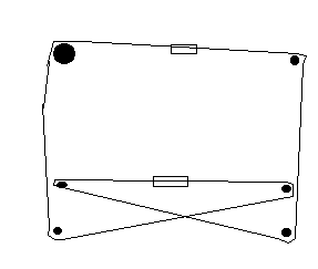
Here is my idea for the X & Y axis to reduce parts. Sorry it is only in Paint as I am not yet familiar enough with blender etc. It is shown with belts for now. I realise it will be slower by using direct drive, but the table area will only be small so I don't think this would matter. There is an error in driving the X axis!
The rods and bars can be held with Prusa's method of clamping.
I am fully aware of what is involved with the electronics and programming. The prop has 8 32bit cpu's on chip which makes code much easier. While I can hand solder the smt with ease it is not easy for most.
Edited 5 time(s). Last edit at 10/14/2013 10:07AM by Traumflug.
|
Re: A micro-mendel variant - help needed August 28, 2010 08:00AM |
Registered: 13 years ago Posts: 128 |
Here is a side profile sketch.
Edited 2 time(s). Last edit at 10/14/2013 10:08AM by Traumflug.

Edited 2 time(s). Last edit at 10/14/2013 10:08AM by Traumflug.
|
Re: A micro-mendel variant - help needed August 28, 2010 10:21AM |
Registered: 14 years ago Posts: 581 |
If you are going to do 3d modeling, Heekscad, Openscad, Freecad, and Art of Illusion all work well. The one I use is Heekscad.
I REALLY suggest you go with belts for X & Y, and avoid NEMA 14. NEMA 14 are the same price as NEMA 17, but are much less available, so you will get an inferior product for more money. The look though the blogs and wiki posts dozens have tried to make an effective theaded X&Y, and all have failed because rods to not accelerate and decelerate quickly enough one at full speed. Belts have very little inertia, rods have a HUGE amount of inertia.
I am working down the same lines, if your interested in shareing the work, give me a PM.
repraplogphase.blogspot.com
|
Re: A micro-mendel variant - help needed August 28, 2010 11:45AM |
Registered: 13 years ago Posts: 128 |
Thanks for the info spacexula. Yes, I am interested in sharing the work so PM sent. I will take your advice and use belts and Nema17.
For a workarea of 100x100mm (4x4") and using the drawings above, there are 2 triangular sides of 3 rods x 230mm [6 x B]. The front and rear (lower) horizontal bars are ~250mm and the upper bar or rod is also ~250mm [3 x C]. The Y axis is two bars ~250mm [2 x Y]. The two vertical rods should be ~200mm [2 x Z]. There are two horizontal rods which connect to the Z axis each side and are ~250mm [2 x W].
The Z axis will require 4 ball bearings to fix the Z bars at the top and bottom. There will be 8 bushes required for the X & Y slides. Each Z axis will have a part which will have 2 captive nuts on the Z axis to give stability to the Z axis. These will be connected by 2 horizontal rods [W]. These rods will hold parts which will in turn hold the extruder.
|
Re: A micro-mendel variant - help needed August 28, 2010 01:06PM |
Registered: 16 years ago Posts: 438 |
It may be just me, but your first drawing looks like you have the belt driving the X axis in a large loop, pinned to the axis (to drag it along when the belt moves) at two points.
But the belt will be moving in opposite directions, and would just pull the axis askew when it tries to move.
You could pin it in two places, but you'd need an extra loop of belt, and isn't belt expensive?
I suppose you could use a section of belt just a little wider than the bed's travel, and use a steel cable for the rest though.
--
I'm building it with Baling Wire
|
Re: A micro-mendel variant - help needed August 28, 2010 11:02PM |
Registered: 13 years ago Posts: 128 |
@jgilmore: you are of course correct - I will need to rethink the X axis. I wanted it to utilise the wider bars for stability and therefore needed to move both ends of the carriage simultaneously. MakerBot quite happily moves the carriage without the extra belt drive so maybe I am just overdesigning this bit.
AFAIK T5 belt is $5/m which is about the same cost as bar & rod, but of course lighter. Of course you need double the length of belt. Pulleys can be made which is an advantage. Rods need nuts and washers.
What I am looking for is a tiny RepRap that can make most of itself and also hopefully make the bigger versions such as Mendel, albeit slowly. I realise some of the Mendel parts are big, so it maybe necessary to join them to achieve this.
I saw Prusa's new X axis design last night (where did I see it???) and it looks simple and I could modify this for my X & Y axis.
Another idea I had was to make the base do X, Y & Z along the lines of the MakerBot and have a completely separate section for fixing the extruder above the workarea. Now this would allow the reprap to be a smaller footprint and the extruder would pack parallel to the base for transport. It would also allow alternative tools such as paste etc to be individually mounted.
|
Re: A micro-mendel variant - help needed August 29, 2010 01:39AM |
Registered: 13 years ago Posts: 128 |
Here is an updated X & Y axis. I have tried to keep the weight centralised. The distance between the bars is approx 50mm.
Any comments appreciated
Presuming a print area of 110x110mm and a carriage (the 2 parts with motors) of 70x70mm and the end plates (the 3 parts with pulleys) of 70x30mm...
The X axis will be (from L to R) = 70 + 55 (travel L) + 70 + 55 (travel R) + 30 = 280mm
The Y axis will be (from front to rear) = 30 + 55 + 70 + 55 + 30 = 240mm
This gives a base size WxD od 280x240mm.
Edited 4 time(s). Last edit at 08/29/2010 06:05AM by cluso99.
Any comments appreciated


Presuming a print area of 110x110mm and a carriage (the 2 parts with motors) of 70x70mm and the end plates (the 3 parts with pulleys) of 70x30mm...
The X axis will be (from L to R) = 70 + 55 (travel L) + 70 + 55 (travel R) + 30 = 280mm
The Y axis will be (from front to rear) = 30 + 55 + 70 + 55 + 30 = 240mm
This gives a base size WxD od 280x240mm.
Edited 4 time(s). Last edit at 08/29/2010 06:05AM by cluso99.
|
Re: A micro-mendel variant - help needed August 29, 2010 06:07AM |
Registered: 13 years ago Posts: 128 |
I have added the Z axis to move the X & Y axis up & down (or else traditional Z carriage for the extruder). 4 threaded rods are used.
The X Axis belt can be fastened at each end saving 2 pulleys and some belt.
Side (End) view.
Note the small horizontal rod (front to rear) at the top. This should allow easier mounting of the 4 vertical Z axis rods with ball-bearings at top & bottom. The extruder will be fixed and mounted to the 2 top horizontal rods (left to right). The extruder being fixed should also help in reducing extruder problems due to movement of the extruder axis.
Some ABS parts.
Edited 13 time(s). Last edit at 10/04/2010 02:24AM by cluso99.


The X Axis belt can be fastened at each end saving 2 pulleys and some belt.


Side (End) view.
Note the small horizontal rod (front to rear) at the top. This should allow easier mounting of the 4 vertical Z axis rods with ball-bearings at top & bottom. The extruder will be fixed and mounted to the 2 top horizontal rods (left to right). The extruder being fixed should also help in reducing extruder problems due to movement of the extruder axis.


Some ABS parts.
Edited 13 time(s). Last edit at 10/04/2010 02:24AM by cluso99.
|
Re: A micro-mendel variant - help needed August 29, 2010 11:32AM |
Registered: 14 years ago Posts: 581 |
All of this in paint?
Dude download Freecad, Heekscad, or Openscad. You have some really good ideas here. If you need prototypes printed let me know. I would be willing to invest some plastic in this idea if you flesh it out some more.
repraplogphase.blogspot.com
Dude download Freecad, Heekscad, or Openscad. You have some really good ideas here. If you need prototypes printed let me know. I would be willing to invest some plastic in this idea if you flesh it out some more.
repraplogphase.blogspot.com
|
Re: A micro-mendel variant - help needed August 29, 2010 04:20PM |
Registered: 13 years ago Posts: 128 |
Yes, it's in paint. I haven't tried any of the cad packages yet and I don't have my test laptop with me which has openscad downloaded ready to try. I will be back home tomorrow so will try openscad. Is that the best for beginners? I have used pcb layout and schematic packages but never cad packages.
Thanks v.much for the offer. I can build part with timber to get the sizing right and then I will chat to you.
BTW the Y axis does not require the pulleys at each end as the belt can be fastened at each end - saves 2 pulleys and 1/2 belt length. Perhaps with a ltttle better positioning of the motor I can remove one of the two pulleys at the motor too.
Also hoping that the nut & washer will not be required on each outside end of the Yaxis as I think I can get enough tension on the bearings with the inside nut & washer. This will reduce the plastic requirement too.
Is it worth dropping down to 1/4" threaded rod for the frame? Maybe I will stick to 5/16" (~8mm) for the Y axis as the Skateboard bearings are cheap and readily available everywhere.
Edited 1 time(s). Last edit at 08/29/2010 04:27PM by cluso99.
|
Re: A micro-mendel variant - help needed August 29, 2010 07:36PM |
Registered: 14 years ago Posts: 581 |
It's all personal preference.
The core team used Art of Illusion a lot
Makerbot folks like Blender (spit)
I Like HeeksCAD
Many people like OpensCAD
Have seen people talking about FreeCAD
repraplogphase.blogspot.com
The core team used Art of Illusion a lot
Makerbot folks like Blender (spit)
I Like HeeksCAD
Many people like OpensCAD
Have seen people talking about FreeCAD
repraplogphase.blogspot.com
|
Re: A micro-mendel variant - help needed August 30, 2010 07:39PM |
Registered: 13 years ago Posts: 128 |
While on the plane I continued to work on the design and have a few more questions about whether these things have been tried...
Z axis
---------
For the Z axis, has anyone tried the alternative of fixing the threaded rod and turning cogs with embedded nuts by motor and belt to move the platform up & down? I am presuming we can make these cogs for a T5 belt and obviously we can leave to space for the embedded nut. What I cannot visualise is how this cog/nut (2 or 4 of them on the same plane as the platform so they go up/down on the rod as they turn) is attached to the platform and what and how bearings would be used. If I stack a bearing above and below the cog so that the outer part of the bearing is what holds the platform, I will need to ensure that the belt can still go around the sandwiched cog and also that the bearing does not bind with the rod, meaning that its ID must be greater than the rod and it will need plastic support on the ID to support it. This method would make the structure more rigid while removing the need for other rods. The motor would be on the platform and move up/down with it.
Any comments, ideas, or is this not feasible, has it been tried before, etc ???
Scaling the Design
---------------------------
I also realised that the design I am working on will scale easily by just extending the Y bar lengths (and belt) for the Y direction and that 200mm or more (part length) is quite easy within the existing design. Similarly, by extending the rods & bars on the X axis (and belts), the X width can be readily extended and that 200mm (part width) is easy. The height will require many rods and bars to be changed, but should still use all the same parts. So, if it works, this should make a family of cheap designs.
Would an initial part height of 100mm be acceptable or do we require more ???
Bushes & Linear Bearings
-------------------------------------
I am planning to use bushes (8) for the small design. My idea for the bushes is to cut/file a flat on the flange and have the plastic carriage extruded with a recess for the flange. By inserting the bush with the flat of the flange facing the recess it should slide in easily and then by rotating the bush it will lock into place in the recess.
For a much larger version, linear bearings can be used. They cost ~$10 each (on eBay) and 4 would be required. I think this much larger version would also require Nema23 Steppers. So this would require a plastic parts change too.
Metric or Imperial
-------------------------
Here in Australia, although we have been metric for approx 30 years, it is still easier to buy imperial nuts and bolts. Therefore, I am planning to use imperial parts initially. It may be that we will require two files of parts to support both metric and imperial versions.
I will have a go at producing the drawing on one of the free CAD programs shortly. I have some business things to tidy up now I am back home before I do a lot more work on this. So while I am thinking, any input would be greatly appreciated.
|
Re: A micro-mendel variant - help needed August 31, 2010 11:36AM |
Registered: 13 years ago Posts: 128 |
Here is the latest thoughts using less rods. The pic is in heekscad but there is a problem with placing the motors and the foreground/background bars/rods not rendering in correct order.
Edited 1 time(s). Last edit at 08/31/2010 11:38AM by cluso99.


Edited 1 time(s). Last edit at 08/31/2010 11:38AM by cluso99.
|
Re: A micro-mendel variant - design help needed September 02, 2010 05:48AM |
Registered: 13 years ago Posts: 128 |
Some more modifications. I am back to making the X & Z axes for the extruder and using the PTFE tubing so the motor/feeder are not on the moving carriage (like some other designs I have seen).
Dimensions are moslty using 200mm... (~8")
8 x 200mm threaded rods
2 x ~170mm threaded rods for Z axiz
2 x ~200mm round bar for Y axis
2 x ~190mm round bar for X axis
1 x 200mm round bar for top carry handle (or threaded rod)
I am looking at making the mounting for the motors (extruded ABS by a Mendel) able to rotate so that I can fold the motors into the unit for transportation so the whole unit should be about 200x200x200mm. The design scales up easily.
I have decided 5/16" (~8mm) is too big for this micro, so I will use 1/4" (~6.35mm). I have found some expensive bearings ($6+ ea) 1/4"IDx5/8"ODx3/16" for the Z axis, so I will now search for a cheaper supplier.
Question
Currently I am a little lost.
Are washers necessary for the nuts when securing the rods to the extruded ABS parts? (saving space)
How much ABS is required around the bolt holes?
Here is my latest work using HeeksCad. I am still learning this - docs are pretty poor. There are a few basic tutorials (thanks to SpaceXula's videos & a Andre Pascual's diagrams).
Edited 2 time(s). Last edit at 09/03/2010 11:09AM by cluso99.
Dimensions are moslty using 200mm... (~8")
8 x 200mm threaded rods
2 x ~170mm threaded rods for Z axiz
2 x ~200mm round bar for Y axis
2 x ~190mm round bar for X axis
1 x 200mm round bar for top carry handle (or threaded rod)
I am looking at making the mounting for the motors (extruded ABS by a Mendel) able to rotate so that I can fold the motors into the unit for transportation so the whole unit should be about 200x200x200mm. The design scales up easily.
I have decided 5/16" (~8mm) is too big for this micro, so I will use 1/4" (~6.35mm). I have found some expensive bearings ($6+ ea) 1/4"IDx5/8"ODx3/16" for the Z axis, so I will now search for a cheaper supplier.
Question
Currently I am a little lost.
Are washers necessary for the nuts when securing the rods to the extruded ABS parts? (saving space)
How much ABS is required around the bolt holes?
Here is my latest work using HeeksCad. I am still learning this - docs are pretty poor. There are a few basic tutorials (thanks to SpaceXula's videos & a Andre Pascual's diagrams).


Edited 2 time(s). Last edit at 09/03/2010 11:09AM by cluso99.
|
Re: A 200mm ~8" micro-mendel variant Latest thoughts & few questions September 02, 2010 07:15AM |
Registered: 14 years ago Posts: 581 |
cluso99, how did you get the nice semi transparent look? I didn't know Heekscad could do that! Do tell do tell!
repraplogphase.blogspot.com
repraplogphase.blogspot.com
|
Re: A 200mm ~8" micro-mendel variant Latest thoughts & few questions September 02, 2010 11:53AM |
Registered: 13 years ago Posts: 128 |
SpaceXula, do you mean the coloring or which object is on top?
The coloring is done by selecting each object and then setting it's color.
To get an object on top, you select the object and then click the 'green tick' which brings it to the front (redraws it). So you have to do each one in order from back to front. Also, each time you change something using the 'green tick' it rearranges the order. BTW, each view is different, so it only does this for the current view, so you have to do it for the other views too if you want it right in them too.
Now a question for you... I am having difficulty in rotating a nut. I drew the nut, and removed the centre. Then I imported it and now I need to rotate it. But the rotation does not occur on the plane I require if I use the angle method. If I rotate it using the handles, it does not do a full 90 degrees because it is not grid aligned. I haven't been able to set the exact size for the nut either as it snaps to the grid (using the object with 6 sides). I could get the washer correct because I used cylinders and specificied the radius and height.
RepRap_030m.heeks
Edited 2 time(s). Last edit at 09/02/2010 12:16PM by cluso99.
|
Re: A 200mm ~8" micro-mendel variant Latest thoughts & few questions September 02, 2010 02:48PM |
Registered: 14 years ago Posts: 581 |
I ment the fact that your objects are semi transparent, all mine are solid, and I have to make them invisible to see through them. To rotate by the angle you need to rotate along the Z axis, but you can just use the handles on the parts to do it to. (The 1 hand is rescale, one is 2 are rotate, 1 is stretch, and 1 is move. be careful you get the right one.
I don't see the "green tick", could you screenshot it?
cluso99 Wrote:
-------------------------------------------------------
> SpaceXula, do you mean the coloring or which
> object is on top?
>
> The coloring is done by selecting each object and
> then setting it's color.
>
> To get an object on top, you select the object and
> then click the 'green tick' which brings it to the
> front (redraws it). So you have to do each one in
> order from back to front. Also, each time you
> change something using the 'green tick' it
> rearranges the order. BTW, each view is different,
> so it only does this for the current view, so you
> have to do it for the other views too if you want
> it right in them too.
>
> Now a question for you... I am having difficulty
> in rotating a nut. I drew the nut, and removed the
> centre. Then I imported it and now I need to
> rotate it. But the rotation does not occur on the
> plane I require if I use the angle method. If I
> rotate it using the handles, it does not do a full
> 90 degrees because it is not grid aligned. I
> haven't been able to set the exact size for the
> nut either as it snaps to the grid (using the
> object with 6 sides). I could get the washer
> correct because I used cylinders and specificied
> the radius and height.
>
>
repraplogphase.blogspot.com
|
Re: A 200mm ~8" micro-mendel variant Latest thoughts & few questions September 03, 2010 12:13AM |
Registered: 13 years ago Posts: 128 |
It is Item 6 on this pic of figure 1 (the take effect tick)
Heeks tutorial part 1 of 4
When I use the rotate handle it will not do a proper rotate because it is not aligned to the grid because of its size. The only way to rotate cleanly would be to size the part to the grid, rotate and then resize to part of the grid.
Heeks tutorial part 1 of 4
When I use the rotate handle it will not do a proper rotate because it is not aligned to the grid because of its size. The only way to rotate cleanly would be to size the part to the grid, rotate and then resize to part of the grid.
|
Re: A 200mm ~8" micro-mendel variant Latest thoughts & few questions September 03, 2010 12:58AM |
Registered: 14 years ago Posts: 581 |
If you use the rotate fuction it rotate from the middle (or where ever you select as center), if you use the handle, then it turns from the opposite corner.
repraplogphase.blogspot.com
repraplogphase.blogspot.com
|
Re: A 200mm ~8" micro-mendel variant Latest thoughts & few questions September 03, 2010 03:41AM |
Registered: 13 years ago Posts: 128 |
Been out shopping... (in Australia)
I have found that 6mm and 8mm threaded rod in 1m lengths are cheaper that 1/4" & 5/16" in 24" and 36". The 8mm Skate Bearings are much cheaper than 1/4" ($1.70 v ~$6.00). Here is what I have purchased...
From Gosford Bolts & Bearings (Central Coast, NSW Australia) Ph (02) 4325 4216 sales-at-boltsbearings.com.au
1 @ M8 1m Allthread $3.74 ea (all +GST 10% so ~ equiv to US$)
2 @ M6 1m Allthread $3.45 ea
4 @ 608-ZRS 8x22x7mm Skate Bearing $1.70 ea
2 @ M8 Coupler (Nut 8mmx25mm long nut) $1.30 ea
4 @ M8 Nuts & small washers $0.60 total
36 @ M6 Nuts & small washers $2.16 total
This will cut into
9 @ M6 x 200mm allthread (for all supports)
2 @ M8 x ~180mm allthread (TBD) (for Z axis)
Still to buy
2 @ M6/M8 x 200mm Round Bar (for Y axis)
2 @ M6/M8 x ~190mm Round Bar (for X axis)
8 @ M6/M8 bushes (or 4 linear bearings??)
Pulleys, belts, etc.
|
Re: Cluso's Micro-Mendel variant = 200mm ~8" Latest thoughts, progress & questions September 03, 2010 09:34AM |
Registered: 13 years ago Posts: 128 |
Thanks spacexula. I have the rotation on HeeksCad working now.
Doing a little research into my decision to go back to placing the Extruder on the movable X carriage (also on Z axis) was that I thought I could get more usable Print Area if I did this. However, I have just realised that it really doesn't give me much extra, if any at all. Maybe 5-10mm max but I can reduce the carriage size and that saves the 5-10mm. Now why this is important? I just read on another thread asking about the springs??? under the print plate. This made me think and if the Extruder is fixed on the X & Y axis then the Print Plate does not require a critical adjustment as it will be in exactly the same position (height) under the Extruder. This means 1 less adjustment and it is a little simpler too. It makes the X, Y & Z motors easier to mount, possibly requiring a little extra height, but saves moving the motors when transporting to save space.
Reprap size of a total width of 200mm (~8") I should have a print width of ~110mm (X axis) and for a depth of ~230mm I should have a print depth of ~140mm (Y axis). Note I am cheating here as the carriage will move out the front and rear of the reprap by ~50mm each way. Total height of the reprap is not yet determined but should be ~250mm which should give a print height of approx ~100+mm.
|
Re: A 200mm ~8" micro-mendel variant Latest thoughts & few questions September 06, 2010 06:45AM |
Registered: 14 years ago Posts: 1,092 |
|
Re: Cluso's Micro-Mendel variant = 200mm ~8" Latest thoughts, progress & questions September 06, 2010 08:45AM |
Registered: 13 years ago Posts: 128 |
|
Re: Cluso's Micro-Mendel variant = 200mm ~8" Latest thoughts, progress & questions September 24, 2010 03:47PM |
Registered: 13 years ago Posts: 128 |
I have been busy with moving house and other things, so not much done in the last few weeks.
While moving I discovered the kids old roller blades. So I ratted them for the bearings. This was interesting as one pair of boots had 5 wheels each with 2 bearings giving me 20 bearings. The other had 4 wheels giving me 16 bearings. BUT, one of them had a smaller bolt with some form of nylon bushes holding in the bearings which may be extremely useful for the carriage bushes. I thought I would pass this on. These boots must be 10 yrs old so I am not sure what current boots are like, but it could be a cheap source for a few bits.
While moving I discovered the kids old roller blades. So I ratted them for the bearings. This was interesting as one pair of boots had 5 wheels each with 2 bearings giving me 20 bearings. The other had 4 wheels giving me 16 bearings. BUT, one of them had a smaller bolt with some form of nylon bushes holding in the bearings which may be extremely useful for the carriage bushes. I thought I would pass this on. These boots must be 10 yrs old so I am not sure what current boots are like, but it could be a cheap source for a few bits.
|
Re: Cluso's Micro-Mendel variant = 200mm ~8" Latest thoughts, progress & questions October 02, 2010 05:30AM |
Registered: 13 years ago Posts: 128 |
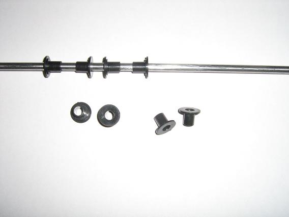
Today I extracted the bearing from the skate wheels. Both skates had 2 bearings per wheel. But one set had bearings with a collar while the other were normal. The normal ones, as I said above, have nylon inserts to 6mm bolts and these fit my 6mm rods obtained from the printer I just pulled apart. I also obtained 6mm rods (and others) from a used Xerox Laser cartridge. Unfortunately, the laser cartridge ones have rubber rollers fused to the 6mm bar and is not easily removed.
The nylon inserts (bushes) work perfectly on the 6mm rod to make the carriages slide with ease. They are 8mm external size with a flange. I have 2x4 wheels (not 2x5 as I thought) which each have 2 bushes, so I have8 16 bushes and I need 4 per carriage, so that covers 2 sets of the X & Y axis as the z axis does not need them.
I have the bearings soaking in kero to see if I can revive them. Otherwise, I have already bought new ones.
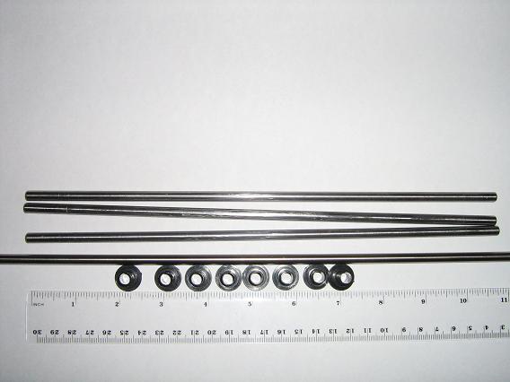
Here are photos of the 6mm threaded rods cut to ~250mm (not 200mm as I made a mistake). Note 6 are 250mm and 2 are slighly shorter at ~246mm due to the threaded rod not quite being 1000mm long. This is not due to cutting loss as the 250mm are finished to ~248mm. I have A4 paper and a ruler and a pair of glasses for size reference.
Edited 2 time(s). Last edit at 10/02/2010 08:18PM by cluso99.
The nylon inserts (bushes) work perfectly on the 6mm rod to make the carriages slide with ease. They are 8mm external size with a flange. I have 2x4 wheels (not 2x5 as I thought) which each have 2 bushes, so I have
I have the bearings soaking in kero to see if I can revive them. Otherwise, I have already bought new ones.
Here are photos of the 6mm threaded rods cut to ~250mm (not 200mm as I made a mistake). Note 6 are 250mm and 2 are slighly shorter at ~246mm due to the threaded rod not quite being 1000mm long. This is not due to cutting loss as the 250mm are finished to ~248mm. I have A4 paper and a ruler and a pair of glasses for size reference.


Edited 2 time(s). Last edit at 10/02/2010 08:18PM by cluso99.
|
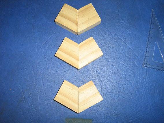
Re: Cluso's Micro-Mendel variant = 200mm ~8" Latest thoughts, progress & questions October 04, 2010 01:45AM |
Registered: 13 years ago Posts: 128 |
I have removed the rubber from the 6mm round bar salvaged from old laser printer cartridges (Xerox Phase 3124). I have 3 @ 275mmx6mm round bars although they have scores making the useful length 230mm plus clamping. While I wait for my 4th cartrige I have a 355mmx6mm round bar from an old Brother DCP-115C bubblejet printer - from the scanner section.
The bushes are from a pair of old roller blades from my kids (roller blades are 10-15 yrs old). The good ones had skate bearings and internal bushes to 6mm bolts and should work perfectly for my X & Y axis making a much simplified and cost reduced X & Y carriage.
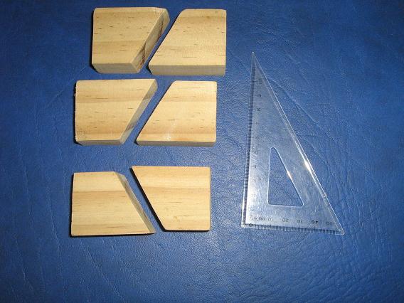
Temporarily I have made some wood brackets for holding the rods together. These are made from 1"x2" timber cut to 3 @ 5" lengths and then in turn they are cut in half at 60 degree angles. Then one end is turned over and glued together, yielding 3 @ 60 degree corners. The glue won't be ready until tomorrow. I am still looking for metal rod fasteners (like I have seen made in plastic on thingiverse) - I need to find the link as alternatives. Once I have all the pieces I will get plastic parts made.
Edited 1 time(s). Last edit at 10/04/2010 01:49AM by cluso99.
The bushes are from a pair of old roller blades from my kids (roller blades are 10-15 yrs old). The good ones had skate bearings and internal bushes to 6mm bolts and should work perfectly for my X & Y axis making a much simplified and cost reduced X & Y carriage.


Temporarily I have made some wood brackets for holding the rods together. These are made from 1"x2" timber cut to 3 @ 5" lengths and then in turn they are cut in half at 60 degree angles. Then one end is turned over and glued together, yielding 3 @ 60 degree corners. The glue won't be ready until tomorrow. I am still looking for metal rod fasteners (like I have seen made in plastic on thingiverse) - I need to find the link as alternatives. Once I have all the pieces I will get plastic parts made.


Edited 1 time(s). Last edit at 10/04/2010 01:49AM by cluso99.

Sorry, only registered users may post in this forum.