Cluso's Micro-Mendel variant = 200-250mm ~8-10"  Latest thoughts, progress & questions
Posted by cluso99
|
Re: Cluso's Micro-Mendel variant = 200mm ~8" Latest thoughts, progress & questions October 04, 2010 04:32AM |
Registered: 13 years ago Posts: 128 |
Here are my latest thoughts...
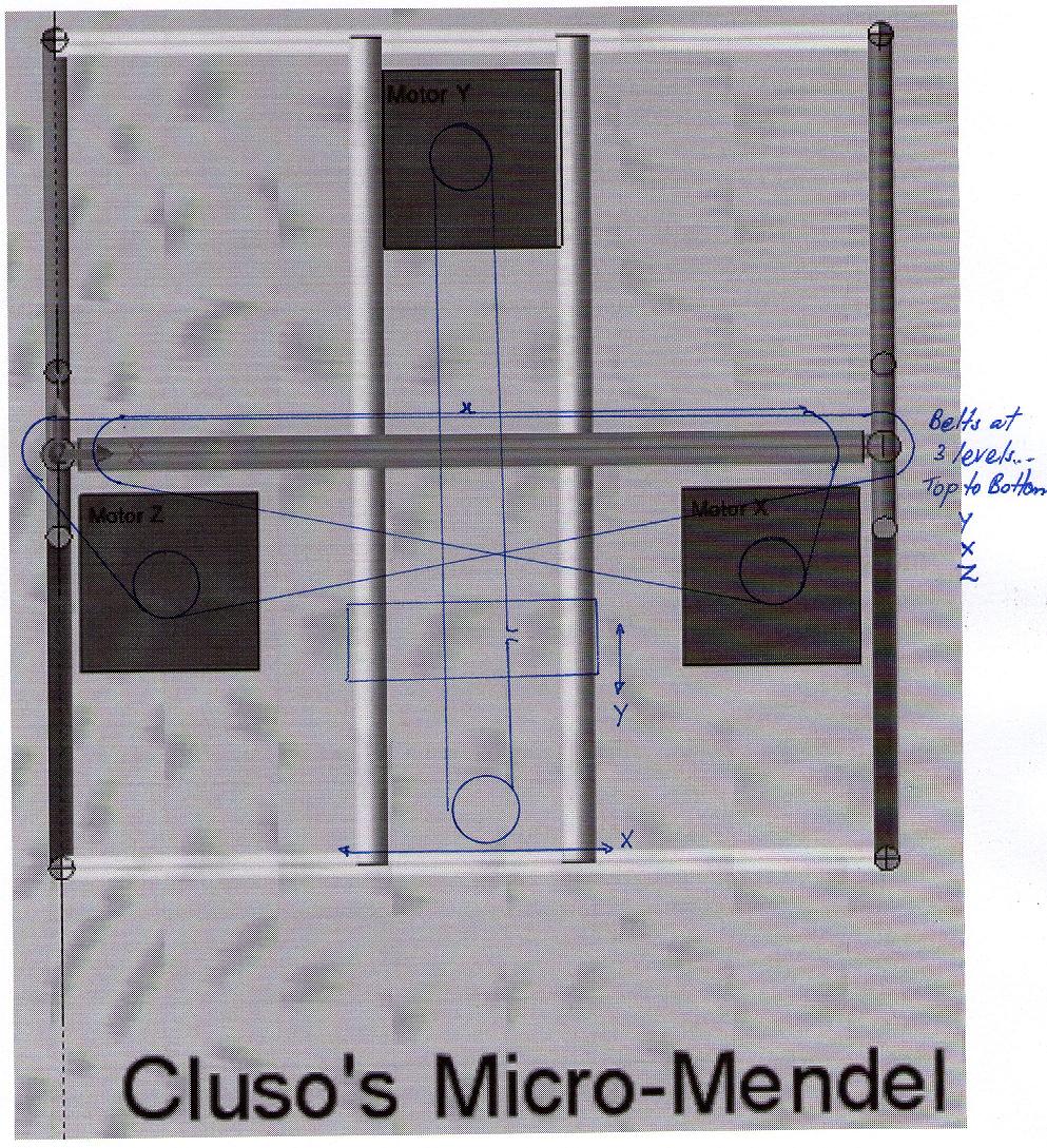
All motors are below the table. The X & Z motors are in a fixed position. The Y motor is attached to one end of the Y axis and moves along the end of the X axis. The Y bars have another Y rod underneath (not shown) which is used to fasten the X belt to which moves the Y axis.
This method, while reducing the usable table width a little, permits the extruder to only move up/down. I am intending to use a Bowden style PTFE tube to feed the plastic.
I think it may be possible to have the X pulleys rotate on the Z rods above the Z cogs.
Edited 1 time(s). Last edit at 10/04/2010 04:35AM by cluso99.
All motors are below the table. The X & Z motors are in a fixed position. The Y motor is attached to one end of the Y axis and moves along the end of the X axis. The Y bars have another Y rod underneath (not shown) which is used to fasten the X belt to which moves the Y axis.
This method, while reducing the usable table width a little, permits the extruder to only move up/down. I am intending to use a Bowden style PTFE tube to feed the plastic.
I think it may be possible to have the X pulleys rotate on the Z rods above the Z cogs.

Edited 1 time(s). Last edit at 10/04/2010 04:35AM by cluso99.
|
Re: Cluso's Micro-Mendel variant = 200mm ~8" Latest thoughts, progress & questions October 04, 2010 06:45AM |
Registered: 13 years ago Posts: 128 |
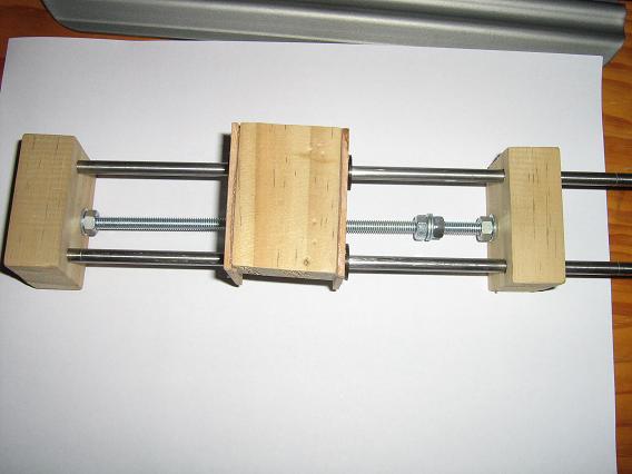
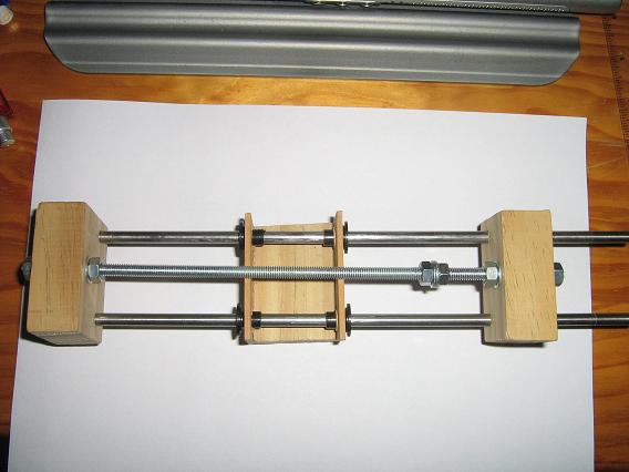
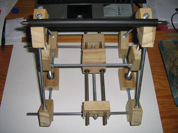
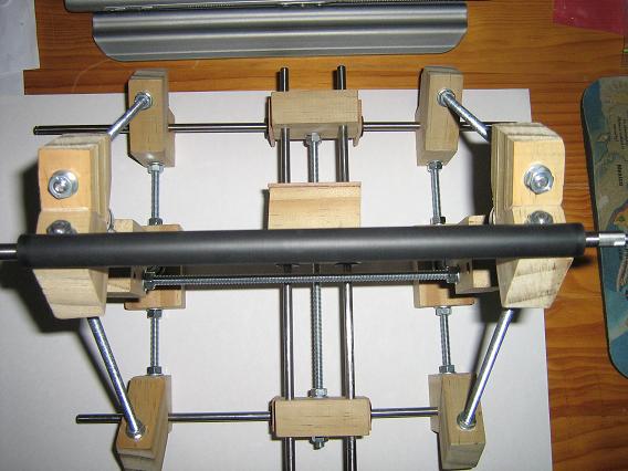
Here are two photos of my Y axis and table carriage. Please ignore it not being properly square. The Y bars need to be cut to length. There will be a platform at one end to mount the Y axis NMEA17 motor. When the bars are held correctly aligned the carriage slides quite freely on the nylon bushes.
The extra nuts & washers will be used to clamp the X axis belt (in the center of the Y axis) and the X bars will be at the ends of the Y axes.
Edited 2 time(s). Last edit at 10/04/2010 06:49AM by cluso99.
The extra nuts & washers will be used to clamp the X axis belt (in the center of the Y axis) and the X bars will be at the ends of the Y axes.


Edited 2 time(s). Last edit at 10/04/2010 06:49AM by cluso99.
|
Re: Cluso's Micro-Mendel variant = 200mm ~8" Latest thoughts, progress & questions October 05, 2010 12:30AM |
Registered: 13 years ago Posts: 128 |
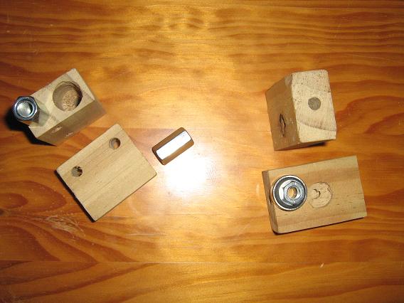
Here is my Z axis parts - currently in wood to determine exact dimensions, etc.
The two pieces on the left are for the vertical mount on the Z axis. The larger hole allows the large hex nut to be inserted in the part and fixed from turning. A plastic piece would be extruded to prevent turning but allow the Z carriage to lift if it hit the piece part or table, and hopefully prevent damage to the extruder. Two horizontal threaded rods (or bars) (in vertical alignment) will be used to hold the extruder bracket which is fixed except for the Z plane (vertical).
The two pieces on the right are the lower Z axiz bracket which is fastened to the lower threaded rod running front to rear on both sides. The bearing and washer and nut sit on top of the bracket and will be fastened in place by panel pins (nails) for now. The recess is to allow the threaded rod in the center (8mm) and the center of the bearing to rotate without touching the bracket - i.e. it can freely rotate. A similar mechanism is used on the top bracket for the top of the Z rod. The rod is therefore held in place by outward force of the nuts against the bearings and no nuts/washers are used on the outer edge of the bearings.
Later I will see if in such a small design I could use 6mm threaded rod for the Z axis too.
Edited 2 time(s). Last edit at 10/05/2010 12:34AM by cluso99.
The two pieces on the left are for the vertical mount on the Z axis. The larger hole allows the large hex nut to be inserted in the part and fixed from turning. A plastic piece would be extruded to prevent turning but allow the Z carriage to lift if it hit the piece part or table, and hopefully prevent damage to the extruder. Two horizontal threaded rods (or bars) (in vertical alignment) will be used to hold the extruder bracket which is fixed except for the Z plane (vertical).

The two pieces on the right are the lower Z axiz bracket which is fastened to the lower threaded rod running front to rear on both sides. The bearing and washer and nut sit on top of the bracket and will be fastened in place by panel pins (nails) for now. The recess is to allow the threaded rod in the center (8mm) and the center of the bearing to rotate without touching the bracket - i.e. it can freely rotate. A similar mechanism is used on the top bracket for the top of the Z rod. The rod is therefore held in place by outward force of the nuts against the bearings and no nuts/washers are used on the outer edge of the bearings.
Later I will see if in such a small design I could use 6mm threaded rod for the Z axis too.
Edited 2 time(s). Last edit at 10/05/2010 12:34AM by cluso99.
|
Re: Cluso's Micro-Mendel variant = 200mm ~8" Latest thoughts, progress & questions October 05, 2010 04:01AM |
Registered: 13 years ago Posts: 128 |
Here is the frame almost complete. Note it is for a prototype and is not really square due to rough drilling etc.
One horizontal threaded rod is missing to hold the extruder. One horizontal rod is missing at the top (a black printer rod has been placed near the final position).
Edited 1 time(s). Last edit at 10/05/2010 04:03AM by cluso99.
One horizontal threaded rod is missing to hold the extruder. One horizontal rod is missing at the top (a black printer rod has been placed near the final position).


Edited 1 time(s). Last edit at 10/05/2010 04:03AM by cluso99.
|
Re: Cluso's Micro-Mendel variant = 200mm ~8" Latest thoughts, progress & questions October 06, 2010 11:12AM |
Registered: 13 years ago Posts: 128 |
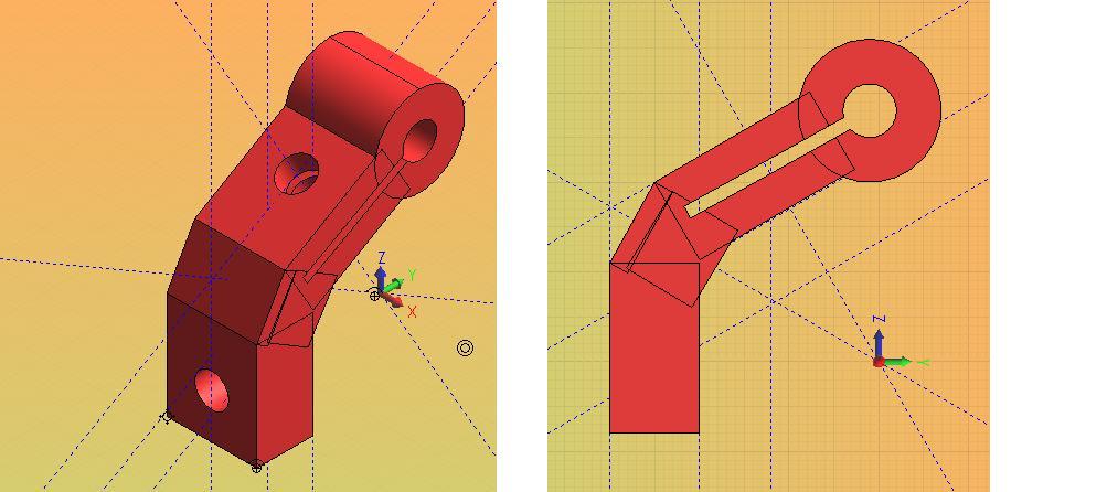
Here is a pic of the bracket that I think may work for all 6 vertices of my micro-mendel. Note the clamp part to hold the round bar. I have included the heekscad file too.
I have allowed 5mm of plastic around the bars and rods and the clamp slot is 1.5mm (the thickness is 10mm -1.5mm so 4.75mm per side). The depth is 16mm. I am using 6mm rods and bars.
Any comments as to whether this part would work and could be made? Have I forgotten anything? Suggestions?
Does anyone have a link to tips for making parts, particularly for webbing a large area - for the carriage and the motor mounts?
Edited 1 time(s). Last edit at 10/06/2010 11:14AM by cluso99.
|
Re: Cluso's Micro-Mendel variant = 200mm ~8" Latest thoughts, progress & questions October 11, 2010 07:18AM |
Registered: 13 years ago Posts: 128 |
Today I purchased another 6mmx1m threaded rod and 20 small washers and 20 nuts. This allowed me to add the extra 2 missing rods.
I also purchased 4 x 626-ZRS bearings 6mmIDx19mmODx6mmthick. These are to test using 6mm rod for the Z axis instead of 8mm. I now have enough 6mm rod for this. The 6mm bearings are quite a bit more expensive than the 8mm 608 skate bearings but reduce the number of different parts (8mm rod, nuts and washers) so it may be economical from that point of view.
I am still intending to scale my micro-mendel down in size - currently the rods are 250mm, but my aim is for 200mm rods for the triangular frame although I may stick with 250mm for the X axis rods.
|
Re: Cluso's Micro-Mendel variant = 200mm ~8" Latest thoughts, progress & questions October 11, 2010 08:32AM |
Registered: 13 years ago Posts: 128 |
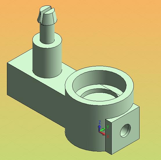
Here is my next part. I still need to allow for clearances/tolerances.
Two of these are required. The are fastened on the lower front/rear rod and hold the Z axis bearing and a pulley for the X axis belt.
I am unsure of the angle the reprap can increase plastic as it rises vertically - can someone please tell me? Also, how do we make a horizontal hole - I have seen a teardrop shape used - how do we get this or does this happen automatically when we generate the Gcode files?
Edited 1 time(s). Last edit at 10/11/2010 08:34AM by cluso99.
Two of these are required. The are fastened on the lower front/rear rod and hold the Z axis bearing and a pulley for the X axis belt.
I am unsure of the angle the reprap can increase plastic as it rises vertically - can someone please tell me? Also, how do we make a horizontal hole - I have seen a teardrop shape used - how do we get this or does this happen automatically when we generate the Gcode files?

Edited 1 time(s). Last edit at 10/11/2010 08:34AM by cluso99.
|
Re: Cluso's Micro-Mendel variant = 200mm ~8" Latest thoughts, progress & questions October 11, 2010 08:56AM |
Registered: 14 years ago Posts: 3,742 |
45°.
No, you have to make the shape yourself out of a cylinder and a cube (or extruded equilateral triangle).
If it is 4mm or smaller you don't need the teardrop shape.
Bob Morrison
Wörth am Rhein, Germany
"Luke, use the source!"
BLOG - PHOTOS - Thingiverse
No, you have to make the shape yourself out of a cylinder and a cube (or extruded equilateral triangle).
If it is 4mm or smaller you don't need the teardrop shape.
Bob Morrison
Wörth am Rhein, Germany
"Luke, use the source!"
BLOG - PHOTOS - Thingiverse
|
Re: Cluso's Micro-Mendel variant = 200mm ~8" Latest thoughts, progress & questions October 11, 2010 09:13AM |
Registered: 13 years ago Posts: 128 |
|
Re: Cluso's Micro-Mendel variant = 200mm ~8" Latest thoughts, progress & questions October 13, 2010 11:38PM |
Registered: 16 years ago Posts: 438 |
You might like to take a look at chylld's replacement repman corner blocks These parts use clamping, replacing a two nuts and two washers on each with a smaller bolt/nut combo. Notice that they also "cradle" the rod, and extend down it a bit for extra stability.
I think that the smaller bolt/nut combo could/should be replaced with a single screw. Make one hole larger to put the screw through, and the other smaller to allow the threads to grip. One small screw (about drywall screw sized) is much cheaper than two M8 nuts and washers. Not to mention easier to install. But designing the part would be much harder.
--
I'm building it with Baling Wire
|
Re: Cluso's Micro-Mendel variant = 200mm ~8" Latest thoughts, progress & questions October 14, 2010 12:10AM |
Registered: 13 years ago Posts: 128 |
jgilmore: I looked at your suggestion/link. My corner vertices are using the diagonal rods 2 nuts & washers to clamp the horizontal (X) bar. Since I am using 6mm rod, the nuts & washers are cheaper than adding 4mm nuts/washers/bolts as they are required anyway. It is not that I haven't thought about trying to clamp the second rod.
re the Z axis: I only use 1 nut/washer at the top and 1 set at the bottom of each 8mm rod. I don't understand what you are saying. If you look at the timber photos and description, you will see that I clamp down the bearing into the plastic (timber housing). The recess in the lower plastic is only to ensure that the bearing does not bind on the plastic on the centre of the bearing. This seems to work quite well and the plastic currently provides a mount on the base to ensure we don't flex the lower front/rear (y) rod. I believe that in my micro version 6mm rod and 626 bearings will work here nicely instead of 8mm. Remember, the extruder only moves on the Z axis and the motor is mounted on the frame, not the Z axis.
Note the 626 bearings are more expensive than the 8mm skate ones, but there are less different parts required. A 1mm thick spacer would convert 6mm to 8mm to allow the cheaper bearings but I dont think we can make a plastic part reliably. The bushes I have are 1mm thick and could do this, but I haven't found a source for these bushes (mine are from an old roller blade set).
I found a ready source of free round-bars (which are expensive anyway) from used laser cartridges and printers.
|
Re: Cluso's Micro-Mendel variant = 200mm ~8" Latest thoughts, progress & questions October 14, 2010 12:59AM |
Registered: 13 years ago Posts: 128 |
Here are calculations for working out the "Usable Table Size" (Maximum Parts Size) using my design...
X Axis
The X axis is governed by the space inside the plastic vertices (i.e. the width between the triangular mounting frame). I have allowed 10mm total for unused space to allow for table overhang and a gap between the plastic.
X Usable Width = (Width between plastic - 10mm ) / 2
e.g. for a usable X width of 110mm you require (2 * 110) +10 = 230mm internal width between vertice plastics (maybe between the rod frame but will have to wait and see).
The X axis is easily extended by using longer X bars and longer rods for the extruder mounting. Nothing else need change.
Y Axis
The Y axis is governed by the length of the Y bars less the plastic holding the ends, and the length of the carriage. The Y platform is permitted to extend past the frame (front and rear) during printing. This gives a larger usable print area.
Y Usable Depth = Depth of bars between plastic - 10mm - Depth of Carriage
e.g. for a usable Y depth of 200mm you require 200 + 10 + 50 = 260mm between plastic, assuming a carriage depth of 50mm.
Z Axis
The Z axis is governed by the usable height in the Z rod and in turn is governed by the triangular dimensions of the frame. I expect this to be ~100mm with my current design.
Scaling the Size
The beauty of this design is that it is scalable by just varying the rod and bar dimensions. All plastics can remain the same.
Motor Mounting
All motors are mounted under the X-Y frame. Currently this includes the extruder stepper although the exact mechanics for this are not yet complete. I am using 4 NEMA 17 Steppers.
Edited 1 time(s). Last edit at 10/14/2010 01:03AM by cluso99.
|
Re: Cluso's Micro-Mendel variant = 200mm ~8" Latest thoughts, progress & questions October 21, 2010 01:14AM |
Registered: 16 years ago Posts: 1,094 |
I cut up some copper pipe for 6mm->8mm bushes.. found some pipe approximately the right size, cut a longitudal slot, cut to length and then formed to the right shape
-----------------------------------------------
Wooden Mendel
Teacup Firmware
-----------------------------------------------
Wooden Mendel
Teacup Firmware

Sorry, only registered users may post in this forum.