Home
>
Reprappers
>
Topic
Anyone recognise this controller?
Posted by cdunbars
|
Anyone recognise this controller? January 06, 2016 10:42PM |
Registered: 8 years ago Posts: 5 |
Is anyone able to identify which LCD controller, labelled YB2004D, this is?
It came as part of a Reprap Prusa i3 kit including a GT2560 board and a PCB Heatbed MK2a, running with Marlin and Repetier Host.
While most features of the printer appear to operate, the display is only illuminating lines 1 and 3 with 'blocks'.
Suggestions please, as to what I need to correct in the Marlin config file?
AND
The heatbed does not activate.
The heatbed thermistor reports a temperature (higher than actual 45 deg in a 25 deg room). The green LED for output D9 does not activate.
Resistance for the heatbed was ~1.5 Ohm, resistance for the thermistor was about 39K Ohm, varying downward with warmth.
Again, suggestions please.
Regards.
Chris.
|
Re: Anyone recognise this controller? January 07, 2016 03:49AM |
Registered: 8 years ago Posts: 5,232 |
It seems to be a regular "reprap discount smart LCD" ( NOT full graphic LCD )
I don't know, if there was a manual for the printer, but AFAIK, the heatbed is on D8.
It is required to supply both input terminals on the green power connector with 12V.
The resistance of the thermistor seems odd. Usually they are 100kOhm at room temp.
What does the hotend thermistor read? What does the manual say about the type of thermistor?
-Olaf
#define REPRAP_DISCOUNT_SMART_CONTROLLER
I don't know, if there was a manual for the printer, but AFAIK, the heatbed is on D8.
It is required to supply both input terminals on the green power connector with 12V.
The resistance of the thermistor seems odd. Usually they are 100kOhm at room temp.
What does the hotend thermistor read? What does the manual say about the type of thermistor?
-Olaf
|
Re: Anyone recognise this controller? January 08, 2016 02:46AM |
Registered: 8 years ago Posts: 5 |
Thankyou Olaf,
The display issue appears sorted.
D8 appears to be the optional second extruder (and trying it didn't progress anything).
The hotend thermistor registered ~94K Ohm at room temp, heading for 81K at around 80 deg.
Presuming the two thermistor's are the same unit, reading a resistance of ~39K Ohm possibly returns an over temperature result, so the board doesn't activate that heatbed power circuit. Repetier Host and the controller both report 43 deg at the moment, but the room is not that temp either. I conclude a faulty thermistor.
Regards,
Chris.
|
Re: Anyone recognise this controller? February 03, 2016 11:35PM |
Registered: 8 years ago Posts: 5 |
Progress - New thermistor fitted to heat bed - Repetier Host reports Heatbed temp consistent with room temp.
However, in manually turning the heatbed 'ON', nothing happens.
The led indicator associated with D9 of the GT2560 board doesn't light up, as D7 does when the extruder heater is manually turned on.
Where, in Marlin, is the 'switch' to activate the heatbed?
However, in manually turning the heatbed 'ON', nothing happens.
The led indicator associated with D9 of the GT2560 board doesn't light up, as D7 does when the extruder heater is manually turned on.
Where, in Marlin, is the 'switch' to activate the heatbed?
|
Re: Anyone recognise this controller? February 04, 2016 09:17AM |
Registered: 9 years ago Posts: 189 |
Quote
cdunbars
Progress - New thermistor fitted to heat bed - Repetier Host reports Heatbed temp consistent with room temp.
However, in manually turning the heatbed 'ON', nothing happens.
The led indicator associated with D9 of the GT2560 board doesn't light up, as D7 does when the extruder heater is manually turned on.
Where, in Marlin, is the 'switch' to activate the heatbed?
'Marlin' is the firmware AKA Software there is not a hardware switch.
You will need to find the hardware pin upon the GT2560 board which goes high when you click the ON button in the software.
Check the pins.h file within the firmware folder, shown when you open configuration.h in the Ardunio IDE when editing
From reading the links below it seems that you have the ATmega2560 processor so you might need to set that in the pins.h file
then tally that up with the firmware that thinks is the correct pin, might need to look at a schematic of the GT2560 board to see which processor pin connects to bed's mosfet, from what you have stated that's D9
Also seems that Geeetech produce the board here are some links
Product details [www.geeetech.com]
Wiki [www.geeetech.com]
One of those should state where on the board the heated bed connection is, also the controller pin which turns on the mosfet for it
Edited 1 time(s). Last edit at 02/04/2016 09:25AM by orictosh.
Supporting 3D Printers with Parts and Build services.
Printer: Ormerod 2 (528.4) Duel extruder set-up with Aluminium X-Rib, RRPro Firmware v1.11-ch (2016-04-08)
|
Re: Anyone recognise this controller? February 04, 2016 09:29AM |
Registered: 8 years ago Posts: 116 |
|
Re: Anyone recognise this controller? February 04, 2016 09:58AM |
Registered: 9 years ago Posts: 189 |
Quote
hoxsiew
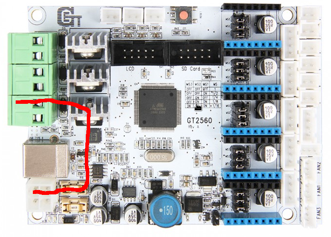
Power for the bed takes the path shown in the attached image.
That's the main 12V High amp power path, bed connection is the green block and power connector is the 4 pin connector.
That mosfet that this path goes though will have it's gate pin connected to a pin upon the processor. That pin has to match the one stated in the firmware.
Edited 1 time(s). Last edit at 02/04/2016 09:59AM by orictosh.
Supporting 3D Printers with Parts and Build services.
Printer: Ormerod 2 (528.4) Duel extruder set-up with Aluminium X-Rib, RRPro Firmware v1.11-ch (2016-04-08)
|
Re: Anyone recognise this controller? February 04, 2016 10:21AM |
Registered: 8 years ago Posts: 116 |
The schematic shows that it connects to PWM3. I don't know how that compares with pins in pins.h. I have this board in mine and use the BOARD_ULTIMAKER in Configuration.h with no other modifications to any other files.
Schematic files are here:
[www.geeetech.com]
Schematic files are here:
[www.geeetech.com]
|
Re: Anyone recognise this controller? February 04, 2016 10:35AM |
Registered: 9 years ago Posts: 189 |
Quote
hoxsiew
The schematic shows that it connects to PWM3. I don't know how that compares with pins in pins.h. I have this board in mine and use the BOARD_ULTIMAKER in Configuration.h with no other modifications to any other files.
Schematic files are here:
[www.geeetech.com]
Ahh, yes setting BOARD_ULTIMAKER in configuration.h will set up the correct pins from processor to the hardware connections.
As it does seem correct; As that GT2560 board is a mash of Arduino ATMega2560, Ramps 1.4 and Ultimaker
Lets see if cdunbars is able to fix the problem with their non-working heat bed.
Supporting 3D Printers with Parts and Build services.
Printer: Ormerod 2 (528.4) Duel extruder set-up with Aluminium X-Rib, RRPro Firmware v1.11-ch (2016-04-08)
|
Re: Anyone recognise this controller? February 07, 2016 09:44AM |
Registered: 8 years ago Posts: 5 |
As I read it, the schematic shows
PWM3 to be Pin 1,
PWM1 to be Pin 6 and
PWM2 to be Pin 7.
"pins.h" for motherboard "7" (as per the Geeetech wiki)
assigns HEATER_BED_PIN 4.
Bearing in mind
HEATER_0_PIN 2 (not PWM1 "6" as the schematic, and which works when manually activated via Repetier-Host V1.0 RC2)
HEATER_1_PIN 3 (nor PWM2 "7" as the schematic - only one heater connected at D7)
Motherboard fuses intact. Firmware setting or faulty mosfet?
|
Re: Anyone recognise this controller? February 07, 2016 12:30PM |
Registered: 9 years ago Posts: 189 |
Quote
cdunbars
As I read it, the schematic shows
PWM3 to be Pin 1,
PWM1 to be Pin 6 and
PWM2 to be Pin 7.
"pins.h" for motherboard "7" (as per the Geeetech wiki)
assigns HEATER_BED_PIN 4.
Bearing in mind
HEATER_0_PIN 2 (not PWM1 "6" as the schematic, and which works when manually activated via Repetier-Host V1.0 RC2)
HEATER_1_PIN 3 (nor PWM2 "7" as the schematic - only one heater connected at D7)
Motherboard fuses intact. Firmware setting or faulty mosfet?
At this point it could be firmware setting
In your configuration.h file is the motherboard setting showing BOARD_ULTIMAKER? As hoxsiew mentions that their set-up uses this same board.
If not set, it to that option, save and upload; Then try the heated bed.
From looking at the schematic pin 4 on the ATMEGA2560 MPU is not used, so that means that the entry in pins.h for motherboard 7 is not correct.
Pin 1 on MPU goes to PWM3 the gate pin upon the Mosfet, which switches on the 12v feed to the heated bed and the led (D9) will flash on/off when temp reached and be steady before reaching the set temperature.
As for the heater being on PIN 2 that's the RX (Receive pin) of a Serial connection on the MPU, not a suitable pin to drive a Mosfet as it should be a PWM signal
reason it could/does work is that PIN2 is opening the gate of the mosfet but will not control it correctly.
PIN 6 on MPU goes to PWM1 the gate pin upon the mosfet, which switches the the 12v fee to the hot-end heater number 1
So to Sum up
Check motherboard setting in configuration.h
and hopefully the pins.h file should read
HEATER_0_PIN 6
HEATER_BED_PIN 1
Let us know how you get on
Chris
Supporting 3D Printers with Parts and Build services.
Printer: Ormerod 2 (528.4) Duel extruder set-up with Aluminium X-Rib, RRPro Firmware v1.11-ch (2016-04-08)
|
Re: Anyone recognise this controller? February 13, 2016 09:37AM |
Registered: 8 years ago Posts: 5 |
No progress. HEATER_0 is definitely pin 2.
The Geeetech wiki specifies "#define MOTHERBOARD 7" for the GT2560 board.
"pins.h" does not contain BOARD_ULTIMAKER
but does contain the following
#if MOTHERBOARD == 7
#define KNOWN_BOARD
/*****************************************************************
* Ultimaker pin assignment
******************************************************************/
#ifndef __AVR_ATmega1280__
#ifndef __AVR_ATmega2560__
#error Oops! Make sure you have 'Arduino Mega' selected from the 'Tools -> Boards' menu.
#endif
#endif
It goes on to define pins, but not a single pin definition is consistent with the pins shown on the schematic.
#define X_STEP_PIN 25 // schematic pin 75
#define X_DIR_PIN 23 // schematic pin 77
#define X_MIN_PIN 22 // schematic pin 78
#define X_MAX_PIN 24 // schematic pin 76
#define X_ENABLE_PIN 27 // schematic pin 73
I obviously don't understand the schematic.
Back to BOARD_ULTIMAKER, would you provide the extract from your pins.h to which the board assignment "BOARD_ULTIMAKER" relates. I'll try that.
|
Re: Anyone recognise this controller? February 15, 2016 12:48PM |
Registered: 8 years ago Posts: 116 |
|
Re: Anyone recognise this controller? February 16, 2016 01:21AM |
Registered: 8 years ago Posts: 2 |
Actually according to the schematic 12V is applied to the heater board at all times. However the ground side of the connector going to the bed gets connected to ground when Q1 gets turn on by the voltage from Pin 1 of the CPU (PWM3). Q1 is a P channel FET and requires a positive Gate to Source voltage of at least 1.6V. When Q1 switches on, it also illuminates D9. R32 prevents noise from building up a charge on the gate (it has a capacitance of about 1700pF) and turning it on. This is a typical circuit where the driving pin has an active pull up and has high impedance when off. The temperature is sensed a a voltage on the ADC9 input (pin 88 of the CPU)
If you are measuring voltages, you will always see 12V on the heater bed. 12V will be on both connections when the heater is not turned on. Checking the voltage on the heat bed might be a way to see if your controller board is the one in the schematic you provided. If there is 12V on both pins, you can take Hot Bed B2 and connect it to ground temporarily without damage to any of the electronics. If you connect Hot Bed A1 to ground by accident, you will blow a fuse or damage your power supply so be careful. D9 should light and the board should heat up. Do not leave this connection on for more than a couple of minutes as the temperature will continue to rise and is uncontrolled.
I have never messed with the configuration files and really not sure I can help but am trying to learn from reading the posts above.. I'm just a retired EE with lots of circuit design experience.
I think your should have something like this in the config file
#define HEATER_BED_PIN 1
#define TEMP_BED_PIN 88
based on what I'm reading from the others but I would make sure that your controller board looks exactly like the one in the Geeetech wiki. Since the pin definitions in the config file don't match the schematic, it is doubtful that you have that exact controller.
tcxoman
|
Re: Anyone recognise this controller? February 16, 2016 09:18AM |
Registered: 8 years ago Posts: 116 |
tcxoman, I appreciate your input. I hadn't actually checked the schematic that closely. Good catch on the hot +12V and switched GND.
As far as the pin numbers go, they are related to the Arduino pinout, not the CPU pinout. As such, PIN4 on an Arduino Mega actually routes to pin 1 on the CPU (and PIN 10 to pin 87, not 88) as per this diagram:
[www.arduino.cc]
As far as the pin numbers go, they are related to the Arduino pinout, not the CPU pinout. As such, PIN4 on an Arduino Mega actually routes to pin 1 on the CPU (and PIN 10 to pin 87, not 88) as per this diagram:
[www.arduino.cc]
|
Re: Anyone recognise this controller? February 17, 2016 10:48AM |
Registered: 8 years ago Posts: 2 |
hoxsiew,
I've never used an Arduino before and it shows. Does the config file reference the CPU pin or Arduino Mega connector number. I've just finished assembling an Original Prusa I3 and am learning how to print. I have not found a "good" easy to use 3D modeling software package. I see the free ones seem to reduce circles or spheres into a standard number of vectors so that as the size of the circle goes up the vector segments become clearly visible on the circumference..
I've never used an Arduino before and it shows. Does the config file reference the CPU pin or Arduino Mega connector number. I've just finished assembling an Original Prusa I3 and am learning how to print. I have not found a "good" easy to use 3D modeling software package. I see the free ones seem to reduce circles or spheres into a standard number of vectors so that as the size of the circle goes up the vector segments become clearly visible on the circumference..
|
Re: Anyone recognise this controller? February 17, 2016 02:03PM |
Registered: 8 years ago Posts: 116 |
The arduino maps their own pin numbers. I think this has to do with the variety of CPUs that the various arduinos can use. They are not just for RAMPS controllers.
As far as CAD, I use FreeCAD which is not the easiest to learn, but has a ton of features once you get to know it. As far as squaring off circles, I think that's more a parameter of the meshing function. FreeCAD lets you mess with the parameters when converting your solid CAD objects to a mesh. There's probably a happy median between CAD solids and "good enough" (for a 3d-print) mesh structures, but I always end up with a mesh that takes 20 minutes to generate because I'm too anal.
As far as CAD, I use FreeCAD which is not the easiest to learn, but has a ton of features once you get to know it. As far as squaring off circles, I think that's more a parameter of the meshing function. FreeCAD lets you mess with the parameters when converting your solid CAD objects to a mesh. There's probably a happy median between CAD solids and "good enough" (for a 3d-print) mesh structures, but I always end up with a mesh that takes 20 minutes to generate because I'm too anal.
Sorry, only registered users may post in this forum.