My Prusa MGN
Posted by bme
|
Re: My Prusa MGN May 24, 2016 04:40PM |
Registered: 7 years ago Posts: 49 |
Here is the result:
[www.youtube.com]
A hole on front = X axis
A hole on left = Y axis
Edited 2 time(s). Last edit at 05/24/2016 04:56PM by bme.
[www.youtube.com]
A hole on front = X axis
A hole on left = Y axis
Edited 2 time(s). Last edit at 05/24/2016 04:56PM by bme.
|
Re: My Prusa MGN May 24, 2016 10:03PM |
Registered: 10 years ago Posts: 363 |
I am enjoying your pictures. If I can achieve layer alignment like your machine I will be happy.
Like you I am using linear rails on my custom machine. My question is this: how precisely planar are your rails that the Y carriage bolts to? Are they perfectly level and planar? I'm concerned if my two rails are not perfect, binding of the blocks on the rail will occur. But I'm not yet at the stage of assembling that so haven't been able to test.
In usage how much room for error in level and planarity have you noticed? Is there any? Or none?
Thanks
New browser from the creator of Opera: [vivaldi.com]
|
Re: My Prusa MGN May 25, 2016 12:56AM |
Registered: 7 years ago Posts: 49 |
I don't know how planar my rails are. I just have a feeling that they are OK when I have them i my hands.
I usually check aluminium plates planarity with this rails.
I didn't notice any error in level and planarity. When I assembly my printer I try to achieve a smooth movements
on all axes and I like to have X axis rail parallel to the heat bed plate.The rest job should auto leveling do.
I usually check aluminium plates planarity with this rails.
I didn't notice any error in level and planarity. When I assembly my printer I try to achieve a smooth movements
on all axes and I like to have X axis rail parallel to the heat bed plate.The rest job should auto leveling do.
|
Re: My Prusa MGN May 25, 2016 01:34AM |
Registered: 7 years ago Posts: 49 |
Here is some two years old images with my privies Prusa I3 without linear rails:
|
Re: My Prusa MGN May 25, 2016 02:04AM |
Registered: 9 years ago Posts: 330 |
It seems that you already had nicely aligned layers. I can't see a huge improvement on the recent pictures compared to the old ones. This could of course be related to the quality and resolution of the pictures, so in reality the situation might be different. (I support what you are doing by the way, it is very good practice to change to linear guides for a rigid structure and consistent print quality).
|
Re: My Prusa MGN May 25, 2016 02:25PM |
Registered: 10 years ago Posts: 363 |
Thanks for the note on planarity. The test in my case will be when I bolt my rails to the extrusions and clamp the carriage to the blocks. It the carriage runs free I will breathe a sigh of relief.
I love the last picture of the yellow clamp. Nice print.
New browser from the creator of Opera: [vivaldi.com]
I love the last picture of the yellow clamp. Nice print.
New browser from the creator of Opera: [vivaldi.com]
|
Re: My Prusa MGN May 25, 2016 02:50PM |
Registered: 7 years ago Posts: 49 |
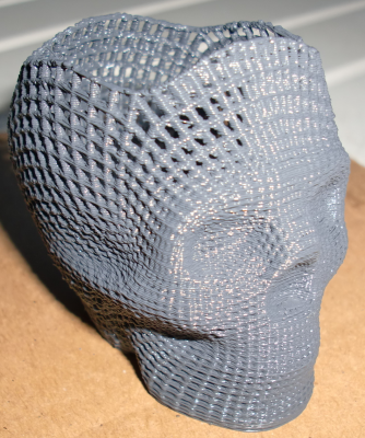
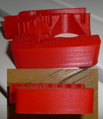
I printed this file from Thingiverse today:
[www.thingiverse.com]
This printer will be a winner in my collection. I prefer a silent printer and this one is just that.
I can see some improvements in Z direction. The layers are more consistent in that direction.
I often use a "word" feeling. Just a feeling to have a 3D printer with a linear rails is good.
This will last longer then previous Prusa i3 with his silent movements and no play. I can now only hear a noise from fans and extruders retraction.
I'll try to reduce extruders noise by making one in nylon plastic.
Edited 1 time(s). Last edit at 05/26/2016 01:30AM by bme.
|
Re: My Prusa MGN May 27, 2016 06:48AM |
Registered: 7 years ago Posts: 7 |
|
Re: My Prusa MGN May 27, 2016 12:04PM |
Registered: 7 years ago Posts: 49 |
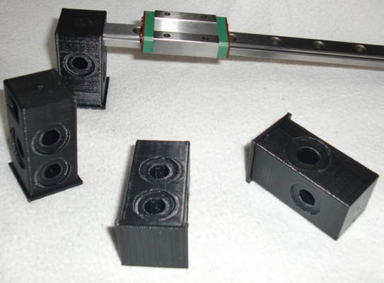
The best way is to search via google words "MGN12", there is images and drawings for a better understanding.
We'll see how everything is mounted when I am finished and satisfied with this printer. There will be STL files for download.
Edited 2 time(s). Last edit at 05/27/2016 02:22PM by bme.
We'll see how everything is mounted when I am finished and satisfied with this printer. There will be STL files for download.
Edited 2 time(s). Last edit at 05/27/2016 02:22PM by bme.
|
Re: My Prusa MGN May 29, 2016 05:21PM |
Registered: 7 years ago Posts: 49 |
|
Re: My Prusa MGN June 01, 2016 09:12AM |
Registered: 7 years ago Posts: 49 |
|
Re: My Prusa MGN June 01, 2016 01:38PM |
Registered: 10 years ago Posts: 363 |
Thanks for posting more pictures and videos.
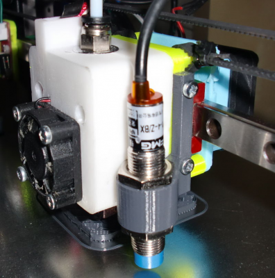
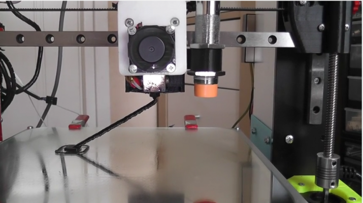
I notice you are using an inductive switch for Z probing AND you have glass or mirror over your aluminum plate. I don't know much about these probes but thought they needed to be able to get very close to the metal bed before triggering. You seem to be proving this is not essential. Can you elaborate on the Z proving with the switch?
New browser from the creator of Opera: [vivaldi.com]
|
Re: My Prusa MGN June 01, 2016 02:47PM |
Registered: 7 years ago Posts: 49 |
I am new in this with ABL. In previous video I use capacitive proximity sensor. That sensor can detect many materials
you put on your heat bed MK2 or MK3 (in my case). Offset is exactly 5 mm (in my case) when triggered, it means that nozzle is 5 mm above
IKEA mirror when triggered. You mentioned inductive switch. That switch react only on a metal surface. A metal surface can be good but I
like IKEA mirror or borosilicate glass on my heat bed.
This sensors can work connecting it directly to RAMPS 5V. Sensing distance will be lower and even
precision.
I recommend follow instruction when connecting those sensors with RAMPS 1.4 or others boards.
Here is some off many instructions on internet:
[premium-forum.fr]
Edited 1 time(s). Last edit at 06/01/2016 02:49PM by bme.
|
Re: My Prusa MGN June 01, 2016 04:05PM |
Registered: 10 years ago Posts: 14,672 |
I've tried many different sorts of sensor including IR, capacitive, inductive, and ultrasonic. They all have advantages and disadvantages:
- Capacitive probes tend to be sensitive to temperature and atmospheric moisture, and are rather large.
- Inductive probes have only a few mm sensing range to aluminium, which means that often they cannot sense aluminium underneath a glass bed. They are also big and heavy.
- Ultrasonic probes are too sensitive to temperature.
- Simple IR probes are too sensitive to the reflectivity of the bed surface, and in some cases to sunlight and incandescent artificial light.
These findings led me to develop the differential IR sensor. It uses two beams of IR light to sense the bed, making it largely insensitive to the bed surface. It has now been adopted as standard equipment by several 3D printer kit manufacturers, including E3D and Think3DPrint3D. You can find more details of it at [miscsolutions.wordpress.com]. Please read the section on bed surface before deciding whether it is right for you.
Large delta printer [miscsolutions.wordpress.com], E3D tool changer, Robotdigg SCARA printer, Crane Quad and Ormerod
Disclosure: I design Duet electronics and work on RepRapFirmware, [duet3d.com].
|
Re: My Prusa MGN June 01, 2016 05:07PM |
Registered: 7 years ago Posts: 49 |
|
Re: My Prusa MGN June 01, 2016 05:45PM |
Registered: 10 years ago Posts: 14,672 |
Yes I use it for both Z homing and bed levelling or delta calibration. Mirror is one of the few surfaces that the sensor does not work well on. When it is used with a transparent surface such as glass, the backing surface should be non-reflecting as far as possible.
Large delta printer [miscsolutions.wordpress.com], E3D tool changer, Robotdigg SCARA printer, Crane Quad and Ormerod
Disclosure: I design Duet electronics and work on RepRapFirmware, [duet3d.com].
Large delta printer [miscsolutions.wordpress.com], E3D tool changer, Robotdigg SCARA printer, Crane Quad and Ormerod
Disclosure: I design Duet electronics and work on RepRapFirmware, [duet3d.com].
|
Re: My Prusa MGN June 01, 2016 08:01PM |
Registered: 10 years ago Posts: 363 |
Thank you @bme and @dc42.
@dc42 your sensor looks excellent and for many reasons appears an excellent solution for Z probing. I haven't worked through all possible scenarios yet but I suspect it will be device I will eventually use for my machine.
One concern I have is how very little higher than the nozzle tip is recommended (1.5mm). This isn't much. Most times prints go well and the surface of the object is flat but sometimes evil things happen and bits or sections of the print lift and I am concerned that dragging the sensor into them would be destructive to it. Can you comment if damage has happened to the sensor from such a case I describe, or am I concerned for no reason? Thank you!
New browser from the creator of Opera: [vivaldi.com]
|
Re: My Prusa MGN June 02, 2016 01:23AM |
Registered: 7 years ago Posts: 49 |
I think one important thing with all those sensors is "cable length" which should be included in a product when
people buying them. At least 70 - 100 cm long.
I wanted to buy a BLTouch sensor first then I saw very short cables included.
I rejected of buying it because of cable length.
Yesterday's print in ABS
Edited 1 time(s). Last edit at 06/02/2016 06:37AM by bme.
people buying them. At least 70 - 100 cm long.
I wanted to buy a BLTouch sensor first then I saw very short cables included.
I rejected of buying it because of cable length.
Yesterday's print in ABS
Edited 1 time(s). Last edit at 06/02/2016 06:37AM by bme.
|
Re: My Prusa MGN June 13, 2016 05:17PM |
Registered: 8 years ago Posts: 88 |
I'm contemplating the idea of doing a CoreXY using MGN12 rails (not really contemplating, few things left to come before I start building it) and after that converting my P3 steel to MGN12.
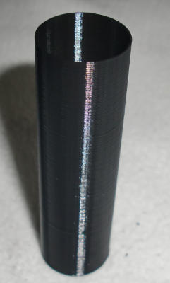
One of the reasons for linear guides is to get rid of patterns on the surface. Now, seeing your printed parts I'm not that happy anymore. All of them have patterns, worse then what I get with LM8UU & 8mm shafts @70mm/sec print speed.
I know about oscillations at tight corners and ghosting, but those fade away after 10-20mm. These simply look the same for the whole length of the perimeter.
Also, since these started to show up, I have strange infills, I don't know if they are related. Watching the nozzle doing the infill, it clearly has different behaviour when doing one line and the reversed one. Maybe there is some rotation in the head carriage (belt is not perfectly in the middle of the X rods), so I don't know if that is related, as I've said and this will be taken care by the linear guides carriage anyway, as there is no torque-induced rotation allowed.
So, the question is: what is causing this aligned ripple on the perimeters?
My ideas:
- bad driver chip => motor vibration
- bad motor (the bearings?)
- bad current, although I've tried reducing near stalling or making it scream and heat like crazy with no visible difference
- bad belt tension, although I have a nice tensioner (toolson mods) so I can afford going from "backlash happy" to really high tension without affecting the Z rods
The X motor shaft (and I assume also Y) has some wobble, but 16 microsteps * 200 steps = 3200 pulses per full rotation. @80 steps/mm it means I have to see this wobble each 3200/80 = 40mm.
|
Re: My Prusa MGN June 14, 2016 01:05AM |
Registered: 7 years ago Posts: 49 |
|
Re: My Prusa MGN June 14, 2016 05:52AM |
Registered: 8 years ago Posts: 88 |
Please ignore the following:
- bad initial Z (had some changes before printing this test and didn't bother to adjust, I did baby stepping during brim)
- part detached during print, so I've stopped the job (the top is moved)
The print speed was ~60mm/sec.
What we can see here is:
- oscillations on corners, which I understand because everything is springy (bed, bearings, rods, printed carriage). These are fading after <20mm travel in the perimeter.
- oscillations/vibrations during the whole perimeter with different periods because the speed was different depending on Z
The second ones I don't understand: belts/motors/frame resonance?
PS. This is some shitty ABS, that's what I was having loaded in the printer because I want to get rid of it. Still, a bad filament has nothing to do with mechanical issues.
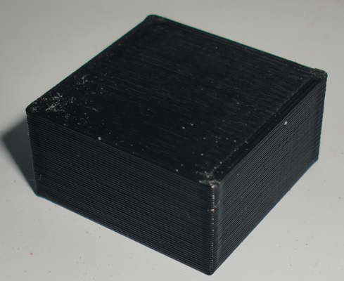
PPS. I've also attached a cube that shows perimeter vibration and strange woven infill pattern (as I've said I suspect a rotation in the X carriage here).
|
Re: My Prusa MGN June 14, 2016 05:59AM |
Registered: 9 years ago Posts: 1,873 |
|
Re: My Prusa MGN June 14, 2016 03:43PM |
Registered: 7 years ago Posts: 49 |
I post some images with higher resolution. An image where you can see the layers and count them if you want.
People can be afraid of that seeing just a negative thing on an image. Usually having those printed parts
in your hands looking at them touching with the fingers seems they are just perfect.
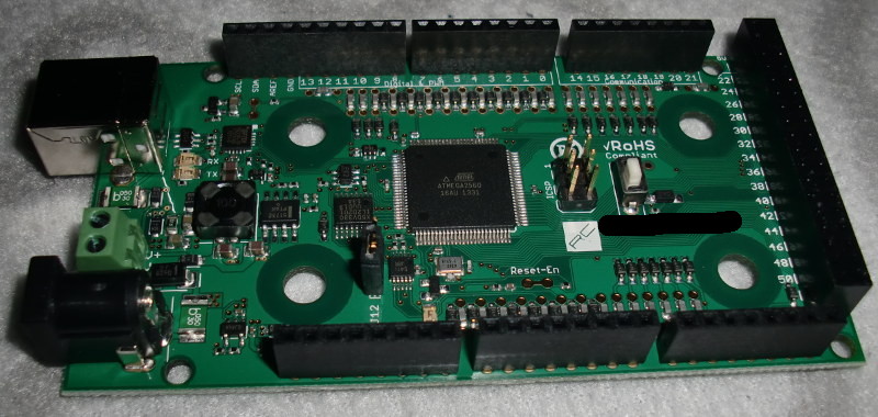
Today arrived something I payed around 160 dollars. Can you guess what is it on the second image?
Edited 1 time(s). Last edit at 06/14/2016 04:28PM by bme.
|
Re: My Prusa MGN June 14, 2016 04:48PM |
Registered: 8 years ago Posts: 88 |
|
Re: My Prusa MGN June 14, 2016 05:21PM |
Registered: 7 years ago Posts: 49 |
sigxcpu --> You prints looks good I am sure. One thing is different compering to my prints.
When I want show people printed parts I make I choose for example less glossy PLA (matte color).
Eventually you can take couple of images with your camera from a different angles.
With glossy plastic I can hide much in a print. Yellow glossy color is perfect for that.
That is an Rugged MEGA 2560:
[www.rugged-circuits.com]
Edited 1 time(s). Last edit at 06/14/2016 05:32PM by bme.
|
Re: My Prusa MGN June 15, 2016 05:53AM |
Registered: 8 years ago Posts: 88 |
The idea was not to hide defects. I took the picture with the best angle and lights that show the issue. I want to understand the source and, if possible, fix it.
When I touch my frame, I can feel the big vibrations that seem to translate to the head.
The steel frame is fine for big forces, but it feels like a big speaker. I have 6 damping legs under the printer, even added motors dampers and nothing changes, except the noise being improved.
I've attached another picture with a big height part that shows the vibrations imprinted on the surface. I'm wondering if (cheap) DSP drivers like 2m542 will fix these.
|
Re: My Prusa MGN June 15, 2016 07:09AM |
Registered: 11 years ago Posts: 5,780 |
I agree with a previous poster- you're over extruding. Also, try adjusting the extruder motor current. Are you microstepping the extruder motor? The ringing you see in the prints is related to acceleration- ringing only occurs where the printer is speeding from zero or slowing to zero after and before a change of direction. I believe the ringing is caused by the rotor acting like a spring. Try playing with the acceleration. Also, using higher driving voltage will use higher peak currents and minimize that behavior. If you're running the system on 12V, try going to 24V.
$100 for an 8 bit arduino? Do they make a matching RAMPS that can handle higher voltage? By the time you add RAMPS you're getting very close to the price of a 32 bit board. All the 32 bit boards I've seen run on 24V and don't require messing around with flaky compilers to make configuration changes, among their many other advantages.
Ultra MegaMax Dominator 3D printer: [drmrehorst.blogspot.com]
|
Re: My Prusa MGN June 15, 2016 12:12PM |
Registered: 8 years ago Posts: 88 |
I'm using a MKS BASE board with "hard-coded" A4982 drivers at 1/16 for all outputs (X,Y,Z,E0,E1) so yes, I'm microstepping it. Now I've got a Titan from E3D, so I've lowered the extruder motor current and it seems better.
I'll try to do the same Kossel part again, using the same filament and see if I get improvements. A 20x20x10mm cube looks a bit better with the Titan and dampers on both X and Y motors.
As I've said, I know about acceleration ringing, but that fades away. These are constant across the whole perimeter and look the same at print acceleration set to 500 or 1500. The XY current is almost at the lower limit (funny fact: the trimpots on MKS BASE are reversed but I didn't see it mentioned anywhere).
Regarding overextrusion, this is tricky. If I lower the extrusion factor during the print I get more and more distinct perimeter lines until they don't touch. 100% linear infills are either as you've seen in the black cube where they have some kind of 3D weave (which looks like overextrusion) or a 2d weave with the lines touching left-right-left if the extrusion factor is too low (remember the different infill lines when switching direction). This is the main reason I'm suspecting something mechanical in XY plane.
Regarding different infill lines when switching direction, I'll try to explain better: a long line starts at 45 degrees and it looks higher than usual, head reaches the perimeter, turns 180 degrees and puts a lower line and also flattens the previous one. Rinse and repeat. I'm pretty sure that the head angle changes either when X switches direction or when Y switches direction. Considering that both belts are not in the middle of the rods, both axes have torque applied and LM8UUs allow some movement, which can be enough to show on the print. Parts feel smooth like @bme says, but they look ugly in certain light angles.
That's why I'm interested in @bme mods with linear guides. I have acquired 3x400mm and 3x600mm chinese MGN12, cleaned and matched the carriages on them to move like butter, so I'm wating for some free time to replace the rods+LM8UU combination with these. The linear guides will not be bothered by some torque, so I'm expecting much better results. (I also have a Tevo Tarantula and replaced the Y carriage with a MGN12 and a single MGN12H and it moves and feels much better).
@bme: sorry to hijack your thread, I'll move somewhere else if you want.
|
Re: My Prusa MGN June 15, 2016 01:17PM |
Registered: 7 years ago Posts: 49 |
There is no problem at all sigxcpu! You or anybody else can post what ever you want. It is nice to see others 3D prints and thinking.
That way we are solving and improving 3D prints.
I think just put for download some STL files or images for someone who like to test things or upgrade his Prusa i3 for example.
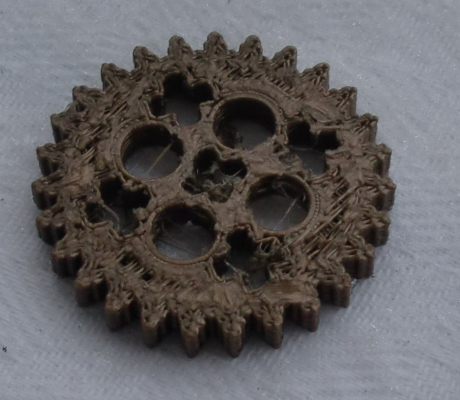
Here is one of my first prints four years ago using CNC machine as 3D printer:
That way we are solving and improving 3D prints.
I think just put for download some STL files or images for someone who like to test things or upgrade his Prusa i3 for example.
Here is one of my first prints four years ago using CNC machine as 3D printer:
|
Re: My Prusa MGN June 15, 2016 03:15PM |
Registered: 7 years ago Posts: 49 |
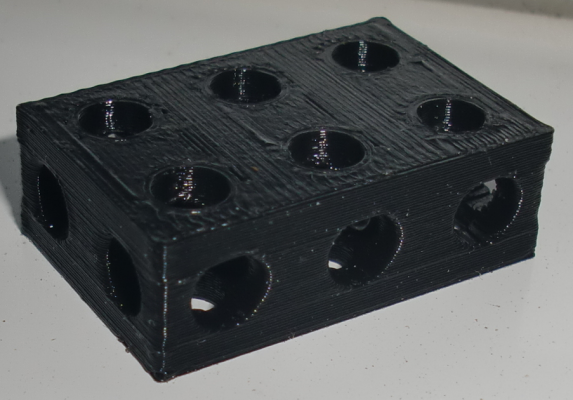
Here is a part from Thingiverse. Anybody can print it and show his result here.
I would like to see how mach better or worse you can do this part with PLA ?
I would like to see how mach better or worse you can do this part with PLA ?
Sorry, only registered users may post in this forum.
