Home
>
Reprappers
>
Topic
A new noob, a new struggle with making a RepRap
Posted by BlenderGuy
|
A new noob, a new struggle with making a RepRap December 14, 2010 05:38PM |
Registered: 13 years ago Posts: 46 |
Hello,
At first, I am quite happy with how the RepRap is setup, the way it works and, just about everything. I have the parts, I have the motors, I have the boards premade and I built the frame from a kit. Following the instructions online, I got everything put together. That part is all okay.
Being a person who loves machines and mechanisms, electronics are a dark art. I think of electronics more like 'the thing that works and makes the motor move'. That being said, I know how to program. My problem is finding the way to get the boards working.
Which is why I love manuals, but the RepRap instructions failed me here. If someone could help me and/or update the RepRap manual for people in my position, I would greatly appreciate it. Since I am a new person at this, this may be valuable for learning how to improve the RepRap site overall.
What I cannot seem to figure out is how to get the motherboard and the extruder board to work. I followed the instructions here [www.reprap.org] as closely as I could.
This is what is occurring
1. When I plug in the serial cable from the USB to TTL, the power does not turn on the motherboard v 1.2
2. The power light on the extruder does turn on, so I do know that power is there
3. When I send commands to the extruder board, it does not respond and, instead, the Arduino states that the board is not connected. I found out that there is a "hold down the reset button and click" sort of of deal, but it did not work for me.
Important factors
1. I do not have the same USB to TTL as specified in the instructions, but I do have a board with the same chip. I do not know what the two jumpers do on the USB to TTL board do. My board has one jumper which specifies 3.3 or 5V as well as about 26 other pins. Each pin has an abbreviated name on the bottom.
2. I took a multimeter and tested each of the connectors on the motherboard. It appears that the pin connected to the VCC on the motherboard does not connect to any other connectors, including both sides of the power LED
3. When I tested the LED with the multimeter, it read 0.05 ohms in both directions.
4. I have not modified the motherboard in any way. It has the 4 Cat-5 Network connectors and the 10x2 block connector.
5. There is a set of 4 pins in the top right hand of the motherboard. They have the names VCC GND SDA and SCL. I could not find out what these were for. The VCC is not connected to the third pin on the serial connector on the left hand side of the motherboard which is VCC on the serial cable.
6. Being a handyman who has worked on houses, I assumed that ground was green and black was power and white was neutral. I did learn that the serial cable needs to be placed in the opposite way to what I believed. I know I have the cable in the right way now.
Small Questions
None of these were specific in the instructions
1. Can I use Cat-5 cables to connect the motors to the motherboard?
2. Can I use Cat-5 to connect the position sensors to the motor controllers?
3. Do I need to modify the motherboard such as removing the Cat-5 and the 2x10 pin connectors?
Requests:
1. In the instructions as to how to set up the USB to TTL board, it would have been helpful to note that the voltage needed was 5V. This was not included in the instructions and I had to search through the forums to find out.
2. Could the wiring diagram in the USB to TTL serial cable have colours? That threw me off for a while.
3. Could there be a wiring diagram where there is a picture of each board with the respective wires coming from them? This would have like a picture of the motor controller with the serial cable with a label MOTHERBOARD. I still do not know how this should look like exactly in the end
4. Could the programming the boards page have links to common problems and solutions?
If someone could help, that would be greatly appreciated. I am a student in third-year Mechanical Engineering at McMaster (Hamilton) and I am from London, Ontario Canada. Doesn't seem like there are many RepRap people nearby, but I don't know much about the RepRap community as is.
|
Re: A new noob, a new struggle with making a RepRap December 15, 2010 03:55AM |
Registered: 14 years ago Posts: 3,742 |
Quote
BlenderGuy
1. When I plug in the serial cable from the USB to TTL, the power does not turn on the motherboard v 1.2
5. ...The VCC is not connected to the third pin on the serial connector on the left hand side of the motherboard which is VCC on the serial cable.
Without this modification how do you expect the motherboard to obtain power?
Quote
BlenderGuy
There is a set of 4 pins in the top right hand of the motherboard. They have the names VCC GND SDA and SCL. I could not find out what these were for.
The SDA & SCL lines are being misused as DIR (direction) and STEP lines for the extruder controller.
They should be attached to D9 and D10 on the extruder board (look at the schematic).
Quote
BlenderGuy
Small Questions
None of these were specific in the instructions
1. Can I use Cat-5 cables to connect the motors to the motherboard?
2. Can I use Cat-5 to connect the position sensors to the motor controllers?
3. Do I need to modify the motherboard such as removing the Cat-5 and the 2x10 pin connectors?
1. Yes.
2. Yes.
3. No. Some do (I did), and some don't. The advantage of doing it is that you get a much cleaner wiring. The disadvantage is it is a lot of work to remove all the old connectors! See the PCB adaptions for Mendel wiki page.
Quote
BlenderGuy
1. In the instructions as to how to set up the USB to TTL board, it would have been helpful to note that the voltage needed was 5V. This was not included in the instructions and I had to search through the forums to find out.
Yes, I agree. The specify the two jumper settings but don't say that one of these selects 5v.
Quote
BlenderGuy
Could the wiring diagram in the USB to TTL serial cable have colours? That threw me off for a while.

The instructions specifically state: "Attach a 6-way 2.54mm-pitch header to the other end of the cable. Colour the RTS end of the header green with a felt-tipped pen, and the GND end black." The colors of the wires is unimportant (they specify the colors as they are ordered in a normal ribbon cable). What is important is the right signal is connected to the right pin.
Quote
BlenderGuy
3. Could there be a wiring diagram where there is a picture of each board with the respective wires coming from them? This would have like a picture of the motor controller with the serial cable with a label MOTHERBOARD. I still do not know how this should look like exactly in the end
Have you viewed the Mendel Wiring video?
Quote
BlenderGuy
3. When I send commands to the extruder board, it does not respond and, instead, the Arduino states that the board is not connected. I found out that there is a "hold down the reset button and click" sort of of deal, but it did not work for me.
For me, the upload only works when the reset button is pressed AFTER starting the upload from the arduino environment and the first text appears - THEN press the reset button. This always works for me.
Bob Morrison
Wörth am Rhein, Germany
"Luke, use the source!"
BLOG - PHOTOS - Thingiverse
|
Re: A new noob, a new struggle with making a RepRap December 16, 2010 01:53PM |
Registered: 13 years ago Posts: 46 |
Thanks for the reply, but I still do not get how to power the board.
I have followed the diagram for how to wire the serial connector. What I mean to say is, when that is plugged in, the power does not turn on. The third pin on the serial connector (which is connected to the VCC wire) does not connect to anything else on the board. I took an ohmmeter and tested between the third pin and the power light and it signals that they are not connected. I tested each other pin and they are all semi-connected, as expected.
So how is the motherboard powered? I thought it was powered via the USB to TTL via the VCC, but the VCC is not connected to anything. Do I need to attach a connector to the top right hand side of the board to provide power? What am I missing?
|
Re: A new noob, a new struggle with making a RepRap December 16, 2010 02:37PM |
Registered: 14 years ago Posts: 3,742 |
I can only repeat what I already wrote:
Without this modification how do you expect the motherboard to obtain power?
See the PCB adaptions for Mendel wiki page.
There is a modification to the Motherboard that you must make if you want to power it from the USB.
Specifically:
Finally on the back of the board solder a link from the fourth pin of the 6-pin USB<->serial connector to the corner pin of the ICSP connector as shown. This allows the entire board to be powered from the USB cable. Make sure the link doesn't short on any of the other connections. (Unlike me, you may care to put a short length of heat-shrink on it to insulate it...)
Bob Morrison
Wörth am Rhein, Germany
"Luke, use the source!"
BLOG - PHOTOS - Thingiverse
Quote
BlenderGuy
1. When I plug in the serial cable from the USB to TTL, the power does not turn on the motherboard v 1.2
5. ...The VCC is not connected to the third pin on the serial connector on the left hand side of the motherboard which is VCC on the serial cable.
Without this modification how do you expect the motherboard to obtain power?
See the PCB adaptions for Mendel wiki page.
There is a modification to the Motherboard that you must make if you want to power it from the USB.
Specifically:

Finally on the back of the board solder a link from the fourth pin of the 6-pin USB<->serial connector to the corner pin of the ICSP connector as shown. This allows the entire board to be powered from the USB cable. Make sure the link doesn't short on any of the other connections. (Unlike me, you may care to put a short length of heat-shrink on it to insulate it...)
Bob Morrison
Wörth am Rhein, Germany
"Luke, use the source!"
BLOG - PHOTOS - Thingiverse
|
Re: A new noob, a new struggle with making a RepRap December 16, 2010 03:28PM |
Registered: 13 years ago Posts: 46 |
rhmorrison,
Thanks for the change, but that doesn't seem to be all of it.
I did the jump as directed, and tested the reading from ground to VCC (1.631ohm) before plugging it into the serial cable. Afterwards, I followed the same instructions on the Microcontroller Firmware Instillation, but the power light did not turn on. The resistance between the VCC on the left hand and top right connectors are 1.680 or 0.504 ohms depending on polarity. I would have believed that they should be the same?
Is there a page I am missing? Some page of instructions describing how to take a purchased, finished board and make it work? I would have thought that a RepRap Motherboard would be a board for a RepRap and would be finished and ready to install.
The electronics I purchased were from ebay an labeled as RepRap Full Electronics Kit with Nichrome Wire and Thermirister.
What am I missing now?
EDIT: Are there any photos or things I could add to help?
Edited 1 time(s). Last edit at 12/16/2010 04:13PM by BlenderGuy.
|
Re: A new noob, a new struggle with making a RepRap December 17, 2010 03:06AM |
Registered: 14 years ago Posts: 3,742 |
Can you upload the extruder firmware to the extruder board using your USB to TTL device?
Directly in your area (on the RepRap Users Map) I only see one individual:
But to the East of you are a number of people (including the designer of the Wade Geared Extruder):
Bob Morrison
Wörth am Rhein, Germany
"Luke, use the source!"
BLOG - PHOTOS - Thingiverse
Directly in your area (on the RepRap Users Map) I only see one individual:

But to the East of you are a number of people (including the designer of the Wade Geared Extruder):

Bob Morrison
Wörth am Rhein, Germany
"Luke, use the source!"
BLOG - PHOTOS - Thingiverse
|
Re: A new noob, a new struggle with making a RepRap December 18, 2010 05:19AM |
Registered: 13 years ago Posts: 103 |
Why are you measuring the resistance? Measure the voltage at that pin. you need to get 5 volts to the relevant places. If you are providing 5 volts on the connection, and you have done the modification, than you should be detecting 5 volts at the correct places, then the power light should be coming on. If not, then there is a break in the connections some where. Likewise check all the places that are suppose to be GND are linked to ground
Cheers
David
Cheers
David
|
Re: A new noob, a new struggle with making a RepRap December 18, 2010 02:20PM |
Registered: 13 years ago Posts: 46 |
I will get back on this once exams are done (last one is on the 22ond).
Davmj
I am measuring resistance because I can measure it without voltage. This board is not working and I do not want to be placing probes on a board where I could cause a jump between VCC and some part of the motherboard. I will, however, once I make a small setup and test this.
As well, I am measuring resistance to see if two points are directly connected. Since the two VCC pins have a resistance between them, there is some part of the board where the circuit is being interrupted. I would have thought that they would be the same, but they are not. Since I don't know much about circuitry or this board, I thought that including that would be important. All boards should have the same resistance between any two points. Since my board is not working, these resistances can be cross-checked in case my board is not wired somehow.
However, yes, I will do some tests with the board powered over the holidays. I just don't want to fry the chip. Powering a board which isn't working doesn't feel right, in my opinion.
|
Re: A new noob, a new struggle with making a RepRap December 18, 2010 04:41PM |
Registered: 13 years ago Posts: 103 |
|
Re: A new noob, a new struggle with making a RepRap December 18, 2010 05:10PM |
Registered: 13 years ago Posts: 46 |
|
Re: A new noob, a new struggle with making a RepRap December 18, 2010 07:33PM |
Registered: 13 years ago Posts: 103 |
I would read through this wiki page in detail: [www.reprap.org] and ensure that all the modifications have been done. If it is still configured up to use an ATX power supply, it will not have some of the modifications done and as a result will not work with just the USB port plugged in.
A simple check of the board should show that once the modifications are done and the ATX power socket has been removed from the board that there is continuity from pin 3 of the TTL interface to the link shown near point C on this picture: [www.reprap.org]
Cheers
David
A simple check of the board should show that once the modifications are done and the ATX power socket has been removed from the board that there is continuity from pin 3 of the TTL interface to the link shown near point C on this picture: [www.reprap.org]
Cheers
David
|
Re: A new noob, a new struggle with making a RepRap December 24, 2010 01:38PM |
Registered: 13 years ago Posts: 46 |
Hello again,
I finished exams and will be back at uni in a few weeks, but I am back at working on the board.
I am following the PCB adaption for Mendel, and I am a little concerned. I have no idea why these modifications are needed. Instead of a 78L33 3.3V regulator, I am using a LM317 with a 240 and 400ohm resistor on a small circuit board, but the result is the same.
As I was going through, it stated on the extruder that "...solder in a 2.54mm screw connector for 12 volt power and a 2.54mm 2-pin header for RS485 communications as shown." I am looking through the forum for what a RS485 is, if it needs to have a MOLEX connector or something which can only be put in one way. I can't even say which direction it needs to go on in, what voltage goes on it or what I need to do with it. I do see on the RepRap overall circuit diagram where the connectors are. I do see that they connect, but why could I not have left the network cable as it was? Could it not have trasmited the voltage along the CAT5 along with the RS485.
What I am really saying is, why? What things do I need to look for when modifying a finished, purchased board to a operational board and what dangers are there? There is very little writing in the article about what these adaptations do. Usually the word "Adaptation" means to make something work in a different way than what it was originally designed for. I will not modify the board any more unless someone specifically says that is what I should do or I know what I am doing and why. Is there a page saying why these things are being done, why the board needs to be changed and what the changes do?
Oh, as for my experience with electronics. I know house and industrial wiring. I also know strain gauge measurement and equipment, hence knowing the LM317 circuit. I know next to nothing about ICs and digital signals, but I know how to clean up analog signals.
|
Re: A new noob, a new struggle with making a RepRap December 24, 2010 06:58PM |
Admin Registered: 17 years ago Posts: 7,879 |
The reason for the "adaptation" is that the gen3 boards are designed for Makerbot, not reprap. They are designed to work with a PC PSU. Reprap aims to work from a single 12 supply.
The reason for changing all the connectors is that when the boards are mounted as described the original connectors are too big and foul the y-chassis.
If you mount the boards close together so they can all be plugged into a PC PSU then you don't need most of the mods.
[www.hydraraptor.blogspot.com]
|
Re: A new noob, a new struggle with making a RepRap December 26, 2010 11:38AM |
Registered: 13 years ago Posts: 46 |
I finished the modifications on the changes sheet. I had read that page before, but it stated the changes were "Optional" without describing why. Well, they do state that the connectors are different, but not describing why. As well, on the boards I got, there was no switch on the motherboard, and instead a three-pin connector. That has been replaced with a switch.
The modifications are done. The power light on the motherboard turns on now. However, as was in the case before, I am only getting a a signal. Neither the extruder or the motherboard seem to be getting a signal from the USB to TTL controller. I then took out a digital osiloscope and have been trying to figure out which of the wires from the USB to TTL send a signal to the board when programming. No wire from the list of 4 (not including ground and VCC).
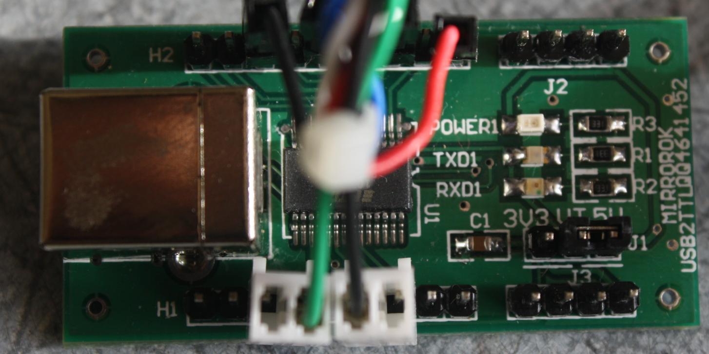
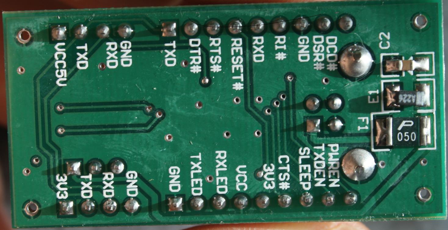
These photos are of the USB to TTL. The chip is a FT232RL, the same chip as listed in the instructions. There are also more connectors, as shown on the back. I have tried to find documentation on this USB to TTL, but there is very little. The windows built-in drivers say that they do work and it shows up as COM 6.
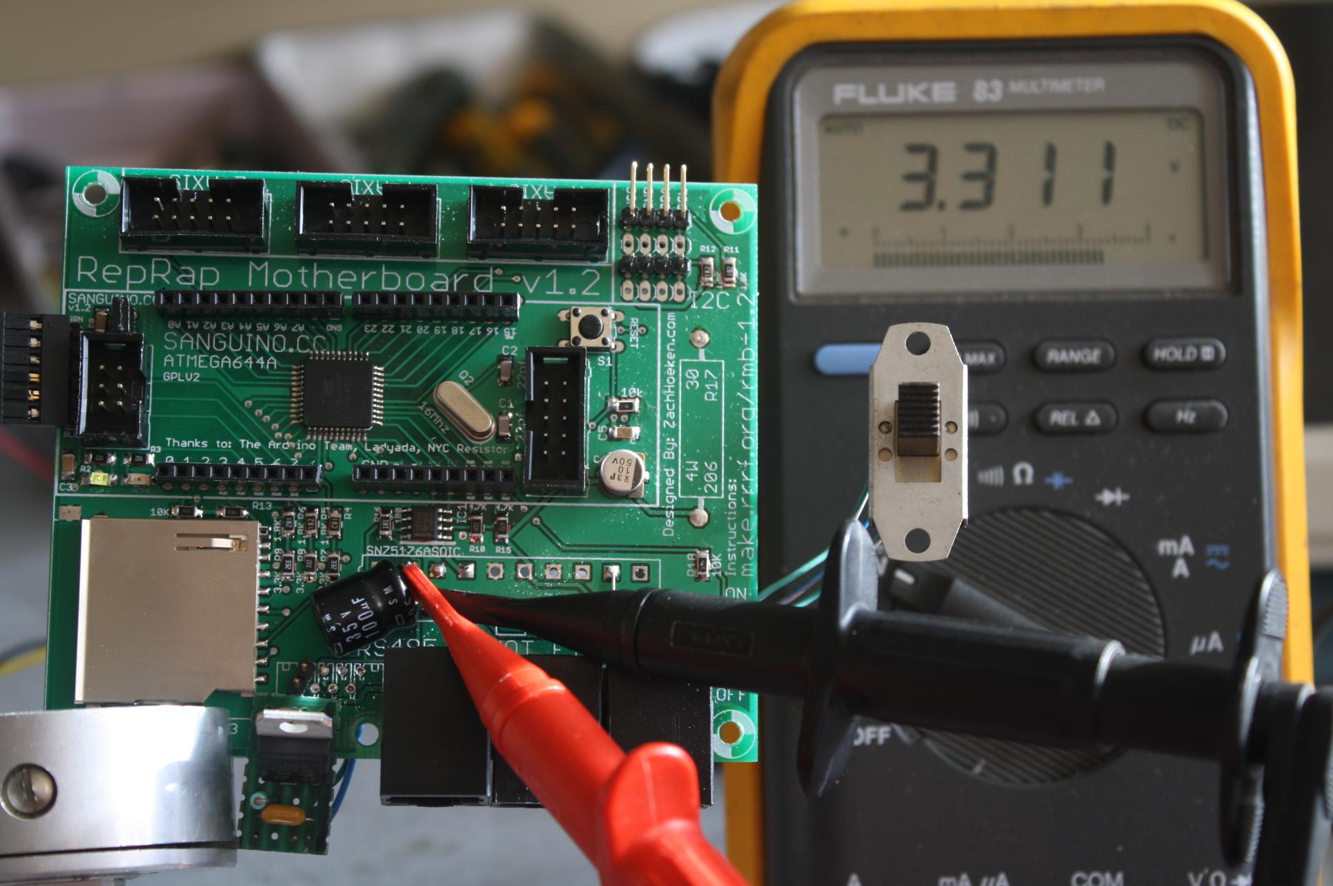
This is the motherboard, showing that there is a stable 3.3V output.
EDIT: Forgot to thank nophead for the info. That helps, for when I was searching online, I was getting different answers from different sources. Makes things make more sense as to why things are the way they are. Thanks.
Edited 1 time(s). Last edit at 12/26/2010 11:57AM by BlenderGuy.
The modifications are done. The power light on the motherboard turns on now. However, as was in the case before, I am only getting a a signal. Neither the extruder or the motherboard seem to be getting a signal from the USB to TTL controller. I then took out a digital osiloscope and have been trying to figure out which of the wires from the USB to TTL send a signal to the board when programming. No wire from the list of 4 (not including ground and VCC).
These photos are of the USB to TTL. The chip is a FT232RL, the same chip as listed in the instructions. There are also more connectors, as shown on the back. I have tried to find documentation on this USB to TTL, but there is very little. The windows built-in drivers say that they do work and it shows up as COM 6.
This is the motherboard, showing that there is a stable 3.3V output.
EDIT: Forgot to thank nophead for the info. That helps, for when I was searching online, I was getting different answers from different sources. Makes things make more sense as to why things are the way they are. Thanks.
Edited 1 time(s). Last edit at 12/26/2010 11:57AM by BlenderGuy.
|
Re: A new noob, a new struggle with making a RepRap December 26, 2010 02:54PM |
Registered: 13 years ago Posts: 46 |
I have done some tests with the oscilloscope and have come up with the following conclusions
On the extruder, I have the power light on and the debug light flickers. When I upload, there is one pulse sent down the RTS# line and three pulses down the RXD line, separated about 470ms.
On the motherboard, I have the power light on, but I have not seen the debug light on at all. When I upload, one pulse is recorded the RTS#, the RXD and the TXD.
I have tried various methods of holding down the reset and lifting off when it says uploading, when it starts compiling and when it is uploading. No response as of yet. I am semi-happy now that I know the board is sending a reply down the RXD line. All I need now is to get it to upload.
|
Re: A new noob, a new struggle with making a RepRap December 26, 2010 04:33PM |
Registered: 16 years ago Posts: 1,094 |
sounds like it's expecting some sort of handshaking, although I'd expect the programming software to turn that off first. if it's running at 3.3v, maybe it's panicking when it gets the 5v signal from the motherboard?
-----------------------------------------------
Wooden Mendel
Teacup Firmware
-----------------------------------------------
Wooden Mendel
Teacup Firmware
|
Re: A new noob, a new struggle with making a RepRap December 31, 2010 10:41PM |
Registered: 13 years ago Posts: 46 |
No progress in the circuitry department. In the Arduino uploader, all I get, as I have always gotten is:
avrdude: stk500_getsync(): not in sync: resp=0x00
avrdude: stk500_disable(): protocol error, expect=0x14, resp=0x51
i.e. the computer is not handshaking with the board
[www.arduino.cc]
I have been working different combinations on it for a few days, but no luck there. Same readouts on the lines as posted above. When I got stressed I worked on getting the geared extruder mounted and installing the motors. I tried installing the arduino again, on another computer, various combinations of holding down the reset, but still no change in the lack of response from the boards. The only time I get a blinking debug light is on the extruder controller when I release the reset button or turn it on. The motherboard has never lit its debug light.
Any advice, other than combinations of holding down the reset button, of getting the board to upload the signal?
As to Triffid Hunter, I do not exactly know what your comment means. The short single bit signals were all that were sent, and were the handshake. Or, more accurately, a failed handshake. What is the handshake supposed to be? Being a mechanical engineering student, I know next to nothing in this field. I have read some on it, but is there some advice out there? The voltage on the given signals is 5v. If this is incorrect, what should I change? I would have thought that nearly everyone would have gone through this.
|
Re: A new noob, a new struggle with making a RepRap January 02, 2011 05:02AM |
Registered: 13 years ago Posts: 103 |
Okay, I think you may have a possible software issue rather than just hardware problem.
With your ardunio uploader have you included the sanguino elements as well in the correct place. When I did this I also found I had to change the board.txt file and make the following change
dmj1@carterton:/usr/share/arduino/hardware/Sanguino$ diff boards.txt.bak boards.txt
4c4
< sanguino.upload.protocol=stk500
---
> sanguino.upload.protocol=arduino
In order to get the upload to work correct to a GEN3 type electronics.
David
|
Re: A new noob, a new struggle with making a RepRap January 07, 2011 12:08PM |
Registered: 13 years ago Posts: 46 |
davmj,
I have tested the what you suggested, but it gave me a series of errors (I will get them again in another post) but it appears (according to the people at my university's IEEE) the board did not come with a bootloader. This was visible (to the people from IEEE) with the lack of blinking debug LED on the motherboard V1.2.
I will get on that now.
|
Re: A new noob, a new struggle with making a RepRap January 13, 2011 04:05PM |
Registered: 13 years ago Posts: 46 |
I am now trying to figure out how to make the bootloader for the Motherboard 1.2 to work. I have been looking for a USBtiny as described here
[reprap.org]
but the company is out of them, so looking online (ebay) I found this
[cgi.ebay.ca]
I "think" it will do the trick. Being a mechanical engineer, I know very little about what is happening. Can I use my USB to TTL to upload to the board? When I was reading, it does not say how the pins are lines up. Where can I find out?
As for the extruder, I still do not know what is up with it. Now the Arduino program crashes when I try to upload the program to the extruder, it crashes and gives the following text
Extruder.cpp: In function 'void setup()':
Extruder:35: error: 'Serial' was not declared in this scope
Extruder.cpp: In member function 'bool intercom::talk()':
intercom:55: error: 'Serial' was not declared in this scope
Extruder.cpp: In member function 'void intercom::tick()':
intercom:176: error: 'Serial' was not declared in this scope
intercom:210: error: 'Serial' was not declared in this scope
Then again, I have been 'fiddiling around' trying to get things to work. I will re-install Arduino again, but my patience is really tiring.
I am more confused now as to what is happening then ever before. I have no idea if I can finish the RepRap. Neither board has worked over the last few months I have been working on them.
|
Re: A new noob, a new struggle with making a RepRap January 17, 2011 11:44PM |
Registered: 13 years ago Posts: 46 |
I am a little torn as to what to do now.
This entire thread has been about me trying to get the two boards to work, but I have not/can't get them to work worth anything. I am really tempted to buy new boards or do something with money now since I can't get them to work.
So, is there a way to order the RepRap Mendle boards
1. premade
2. finished / finalized / no soldering required / no modifications
3. ready to install when I plug it in for the first time
4. can communicate with the computer
Those were the expectations I had of the boards I got.
Another option would be to ship/send to someone else and pay for it. Is there a way I could send the boards to someone, get them to program them and get the boards back? I don't know exactly where I would go, or who to ask for that. I have spent close to a grand on this and I just want it to start working.
I guess my biggest problem is I DON'T KNOW INTEGRATED CIRCUITS. I have spent (wasted) many days trying to get something other than an error out of these boards and I am tempted to just start over with something that works. Is there something that works?
|
Re: A new noob, a new struggle with making a RepRap January 18, 2011 02:08AM |
Registered: 13 years ago Posts: 384 |
Quote
BlenderGuy
Extruder.cpp: In function 'void setup()':
Extruder:35: error: 'Serial' was not declared in this scope
Extruder.cpp: In member function 'bool intercom::talk()':
intercom:55: error: 'Serial' was not declared in this scope
Extruder.cpp: In member function 'void intercom::tick()':
intercom:176: error: 'Serial' was not declared in this scope
intercom:210: error: 'Serial' was not declared in this scope
This just looks like you picked the wrong board in the Arduino program.
Makerbot has boards available [store.makerbot.com]
[store.makerbot.com]
Quote
Makerbot
* Fully assembled, pre-programmed board-- no soldering or AVR programmer required!
I am willing to take a look at your boards, at your risk of course
 Send me a e-mail if you want that, maybe we can arrange something.
reprapworld.com
PLA, ABS, PETG multiple colors (3 and 1.75 mm) €16,49 / kg
Megatronics 3.0 €79.99 / Minitronics €37,19
|
Re: A new noob, a new struggle with making a RepRap February 08, 2011 07:57PM |
Registered: 13 years ago Posts: 46 |
Things are still not working, so I will try to write this as clearly as possible
Request:
A working circuit board which will control the RepRap Mendel. What boards work and what boards do not work? Is there a board which has consistently worked?
What I have and have done:
Ordered a complete RepRap kit from Makerbot.com
[store.makerbot.com]
Followed instructions on RepRap and the instructions listed above
Result
Two boards which, when I try to link them to the computer and program them, consistently give an error as follows
avrdude: stk500_getsync(): not in sync: resp=0x00
avrdude: stk500_disable(): protocol error, expect=0x14, resp=0x51
Communication / experimentation
I have spoken to people who deal with arduinos and they have either stated that they do not deal with this type of issue or do not know how to help me. They have repetitively said that arduino chips are easy and simple.
I have done a few probe tests on the signals being sent to and from the computer via the USB to TTL cable. The results were listed above.
I have spoken to brupje and he has offered to look at the boards. However, with everything included, it would cost over $100 which I am declining as the result is uncertain.
Final Question
I know that nearly every RepRap on this forum has a board linked to it. I know that I can get a board which will communicate with a computer. My question is: What are these boards which communicate with the computer and how can I get one and how can I get it to communicate with the computer? I am willing to purchase a new set of boards. What boards can I purchase?
|
Re: A new noob, a new struggle with making a RepRap February 08, 2011 08:24PM |
Registered: 13 years ago Posts: 643 |
Gen6 or RAMPS. Gen6 is currently unavailable as Mendel Parts is closed to clear their current orders and move to a new location. They say they'll be back in a week or two. RAMPS comes in kit or complete form, from ultimachine. There may be other sellers of both electronics if you look for them.
|
Re: A new noob, a new struggle with making a RepRap May 15, 2011 05:41PM |
Registered: 12 years ago Posts: 2 |
Your problem with the compilation of the extruder firmware is probably because you used version 0022 of Arduino.
I had the same problem but after reading this thread :
extruder serial was not declared in this scope
I tried with version 0021 and then it worked...
I had the same problem but after reading this thread :
extruder serial was not declared in this scope
I tried with version 0021 and then it worked...
Sorry, only registered users may post in this forum.