Home
>
Reprappers
>
Topic
Cast tooling plate print bed flatness
Posted by the_digital_dentist
|
Cast tooling plate print bed flatness July 31, 2016 08:27PM |
Registered: 11 years ago Posts: 5,780 |
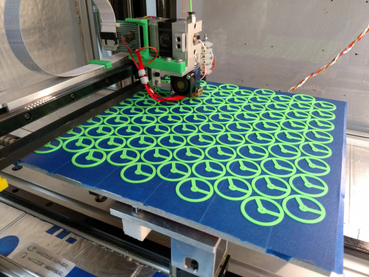
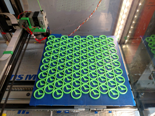
I have been advocating cast tooling plate for a couple years because it is flat and thermally conductive. For anyone who doubts the flatness and suitability of cast aluminum for a 3D printer bed, here is a print I am running right now- 85 Nerdy Derby wheels all printing in one go on an unheated cast tooling plate bed with a layer of kapton tape and blue painter's tape, no glass. A couple of the wheels are literally printing on top of the leveling screws (probably can't do that with ABS) and some are literally at the edge of the plate (at the back of the photo). It looks like I might be able to fit 5 more wheels on the plate, so maybe the next run will have 90 wheels.
The bed plate is 12.5" x 12" x 1/4" (317 x 305 x 6.35 mm), and the wheels are 32 mm dia., spaced 33 mm center to center.
Yes, I know the wheels won't be "balanced".
Ultra MegaMax Dominator 3D printer: [drmrehorst.blogspot.com]
The bed plate is 12.5" x 12" x 1/4" (317 x 305 x 6.35 mm), and the wheels are 32 mm dia., spaced 33 mm center to center.
Yes, I know the wheels won't be "balanced".
Ultra MegaMax Dominator 3D printer: [drmrehorst.blogspot.com]
|
Re: Cast tooling plate print bed flatness July 31, 2016 10:50PM |
Registered: 10 years ago Posts: 140 |
|
Re: Cast tooling plate print bed flatness August 01, 2016 05:44AM |
Registered: 10 years ago Posts: 38 |
|
Re: Cast tooling plate print bed flatness August 01, 2016 11:15AM |
Registered: 7 years ago Posts: 84 |
|
Re: Cast tooling plate print bed flatness August 03, 2016 12:29AM |
Registered: 11 years ago Posts: 5,780 |
|
Re: Cast tooling plate print bed flatness August 03, 2016 09:43AM |
Registered: 7 years ago Posts: 558 |
I can understand your cast aluminum tooling plate for a machine that moved the bed in the Y plane or for a machine with a fixed bed like a delta, but I don't agree with it for a machine that would raise and lower the plate such as a CoreXY design. It would be too heavy compared to what else is out there.
|
Re: Cast tooling plate print bed flatness August 03, 2016 11:56AM |
Registered: 11 years ago Posts: 5,780 |
Actually, you've got it completely upside down.
Moving the bed in the Y axis is a problem because the high moving mass is difficult to keep under control at print speeds, especially if you try to print fast. In my printer I installed a precision ground ball screw, 425 oz-in stepper, DSP driver, and 32V power supply to move the Y axis. I also used fully supported linear guides instead of flexy, end-supported rails. All that to print at a top speed of 50 mm/sec. A recent glass bed replacement by cast tooling plate in a Taz printer seems to perform OK without any changes to the drive mechanism, but that was a surprise. The Taz uses low acceleration and so far we've been keeping the print/motion speed under 50 mm/sec.
Raising and lowering a bed in the Z axis is usually done using screws which effectively multiply the motor torque. As a result, mass of the bed is usually not a problem for machines that move the bed in the Z axis. Z axis motion during printing is typically just dropping the bed a few hundred microns once each layer, unless you enable Z lift on retraction, then it becomes raise and lower a few hundred microns a few times each layer.
Edited 2 time(s). Last edit at 08/03/2016 12:01PM by the_digital_dentist.
Ultra MegaMax Dominator 3D printer: [drmrehorst.blogspot.com]
|
Re: Cast tooling plate print bed flatness August 03, 2016 01:52PM |
Registered: 8 years ago Posts: 153 |
I'm designing a cartesian with a cantilevered Z stage with single screw, twin linear guides, and a cast Al tooling plate as the bed (12" x 12" x 1/4"). According to my fairly rigorous FEA, if I print 4kg of plastic onto the bed, I will see about 25 microns of deflection total (after leveling out the original deflection)...
I don't think the plate is too heavy, but the z axis certainly won't be fast.
I don't think the plate is too heavy, but the z axis certainly won't be fast.
|
Re: Cast tooling plate print bed flatness August 04, 2016 04:04PM |
Registered: 7 years ago Posts: 109 |
Quote
PDBeal
I can understand your cast aluminum tooling plate for a machine that moved the bed in the Y plane or for a machine with a fixed bed like a delta, but I don't agree with it for a machine that would raise and lower the plate such as a CoreXY design. It would be too heavy compared to what else is out there.
I just finished my printer with the bed on the Z axis. It has a 400x400mm large aluminium tooling plate 8mm thick, cantilevered on two heavy duty aluminium shelf brackets, single lead screw 10x2, two 16mm linear rods, 4 linear bearings with aluminium blocks, everything bolted on a 245x120mm 15mm thick. Stepper is a 60Nm nema 17, no gear reduction. I haven't weighted everything yet, but that should be around 6-7 Kg. I have no problem lifting the bed, no missing steps and it has plenty of power left. I could even do "head lift" during retraction.
|
Re: Cast tooling plate print bed flatness August 04, 2016 04:53PM |
Registered: 8 years ago Posts: 622 |
Quote
unromeo21
Quote
PDBeal
I can understand your cast aluminum tooling plate for a machine that moved the bed in the Y plane or for a machine with a fixed bed like a delta, but I don't agree with it for a machine that would raise and lower the plate such as a CoreXY design. It would be too heavy compared to what else is out there.
I just finished my printer with the bed on the Z axis. It has a 400x400mm large aluminium tooling plate 8mm thick, cantilevered on two heavy duty aluminium shelf brackets, single lead screw 10x2, two 16mm linear rods, 4 linear bearings with aluminium blocks, everything bolted on a 245x120mm 15mm thick. Stepper is a 60Nm nema 17, no gear reduction. I haven't weighted everything yet, but that should be around 6-7 Kg. I have no problem lifting the bed, no missing steps and it has plenty of power left. I could even do "head lift" during retraction.
Glad to hear that. The one I'm building is also 400 x 400 but 10mm thick aluminium tooling plate. Two 6mm thick layers of Thermoboard under it and 6mm of glass on top ( I like to have removable, interchangeable build surfaces). All bolted to 2020 extrusion. Two linear guides, 3 off 8mm x 1mm screws but with a single closed loop belt and motor. Also no gearing. it weighs in a 7.2 kg and I was wondering if the motor would be good enough but it sounds like it will be, especially as my thread pitch is half of yours. Reassuring to know...

|
Re: Cast tooling plate print bed flatness August 17, 2016 08:44AM |
Registered: 11 years ago Posts: 5,780 |
You're insulating both the underside and the top side of the aluminum plate. Insulating the top side adds a large thermal resistance that will have a long time constant- the surface temperature will take a long time to eventually approach the temperature of the aluminum plate, and will not reach its temperature. If you want 105C on the print surface you'll have to set the bed temperature quite a bit higher and wait quite a while for it to get to the desired print temperature.
I know you're all about swapping glass plates for production speed- but the glass plates are slowing down the heat-up time and messing up the temperature regulation. Any air flow across the glass plate will drop the surface temperature but the control system tied to the aluminum will be unaware of the change in surface temperature until long after it has happened. Its response will be delayed due to the glass being an insulator.
People usually insulate the underside of the bed plate in an effort to get an underpowered heater to deliver the desired top side temperature. If your heater is adequately powered (0.4 W/cm^2 or more) you don't need underside insulation for the top side of the bed plate to get to print temperatures. Insulating the underside increases the time it will take for the plate to cool off when the print is finished.
I know you don't like to wait for the bed to cool off before you can start the next print, but by adding all that insulation to the top and bottom of the heated plate you're artificially increasing the heat up and cool down times. I'll bet if you tried printing with and without all the insulation you'd find that faster time to start printing and faster cool down without the insulation would be about the same as the longer heat up time with 6 mm of glass on the bed plate. Have you considered speeding up the cooling by kicking on a fan to blow on the uninsulated bed after a print has finished? That way you'd get fast heat up, better temperature regulation, and fast cool down without all the extra mass, and risk of glass breakage. I'll bet one fan is cheaper than one or a few pieces of glass, too.
Ultra MegaMax Dominator 3D printer: [drmrehorst.blogspot.com]
|
Re: Cast tooling plate print bed flatness August 17, 2016 10:33AM |
Registered: 8 years ago Posts: 622 |
Yeh, I hear what you are saying but the cool down time doesn't matter because at the end of the print, I'll just swap out one piece of glass for another. The one that comes off can go in the fridge if I want. The insulation under the bed should help the heat up time and it's an 800W AC mains heater. It'll also save me some money by limiting the heat loss so the heater won't have to work so hard. I have no problem with setting the bed temperature higher in order to achieve the desired surface temperature.
I've had the glass sandblasted and BriteGuard coated and I'm hoping that I can print directly with no tape/paste/goo or other print surface. It may not work - dunno - but it'll be a real plus if it does. Also, if I can't print directly on to it and because I have 3 pieces of glass, I've effectively got 6 print surfaces which can be pre-prepared with Kapton, blue tape, or whatever I choose to suit different materials.
If in then end I find I have problems, I'll swap the glass for aluminium or some such so I still have a selection of removable print surfaces on top of my main bed. The 10mm thick machined aluminium plate cost me a lot of money. Then I invested a fair bit of time machining a slot in the underside to accommodate a PT100 as well as drilling and countersinking mounting holes. I don't want to risk damaging it by printing directly on to it, or even accidentally dropping something sharp on it when it's not in use. I'd rather have a "sacrificial" print surface of some sort.
|
Re: Cast tooling plate print bed flatness August 19, 2016 11:12AM |
Registered: 8 years ago Posts: 601 |
Quote
the_digital_dentist
Have you considered speeding up the cooling by kicking on a fan to blow on the uninsulated bed after a print has finished? That way you'd get fast heat up, better temperature regulation, and fast cool down without all the extra mass, and risk of glass breakage. I'll bet one fan is cheaper than one or a few pieces of glass, too.
Using a fan to cool down ABS prints increases the amount of post-print warping. By this, I mean warping that will happen after the print, most likely due to the design itself. I recently had a job to print 8 large ABS mounts, which consisted of 8 legs on a circle, with 4 sprues attached to an inner circle. For about 30 minutes after printing, the pieces would start to warp as they cooled as the contraction rates of the inner circle were different to that of the outer circle. This would cause the centre to warp inwards and upwards.
As each print took around 6 hours, I used a fan on the first few to speed up the time between prints, but all this caused was further warping of the piece post-printing by as much as a few mm's. A gradual cool-down of the piece is much better.
|
Re: Cast tooling plate print bed flatness August 19, 2016 12:25PM |
Registered: 8 years ago Posts: 153 |
|
Re: Cast tooling plate print bed flatness August 19, 2016 01:31PM |
Registered: 8 years ago Posts: 601 |
Quote
n8bot
This is why I love PEI as a print surface. It doesn't lose its grip on the part while it cools down, so the parts don't warp.
I use Printbite, which works on a similar principle to PEI I believe. The warping issue with active cooling at the end of a print would likely affect it in the same way.
|
Re: Cast tooling plate print bed flatness August 19, 2016 04:08PM |
Registered: 8 years ago Posts: 153 |
|
Re: Cast tooling plate print bed flatness August 21, 2016 06:38PM |
Registered: 11 years ago Posts: 5,780 |
Quote
Origamib
Using a fan to cool down ABS prints increases the amount of post-print warping. By this, I mean warping that will happen after the print, most likely due to the design itself. I recently had a job to print 8 large ABS mounts, which consisted of 8 legs on a circle, with 4 sprues attached to an inner circle. For about 30 minutes after printing, the pieces would start to warp as they cooled as the contraction rates of the inner circle were different to that of the outer circle. This would cause the centre to warp inwards and upwards.
As each print took around 6 hours, I used a fan on the first few to speed up the time between prints, but all this caused was further warping of the piece post-printing by as much as a few mm's. A gradual cool-down of the piece is much better.
So swapping glass plates when printing ABS would be counterproductive... The point of swapping the glass plates for most is to get back to printing faster because cool-down takes too long. If you swap out the glass and throw the plate and print in the freezer to cool it off quickly and get it to let go of the plate it will warp. Printing PLA doesn't require a heated bed if you print on blue painter's tape, so the print can be taken off the bed as soon as it is finished, also making swapping glass plates pointless. hmmmm...
Ultra MegaMax Dominator 3D printer: [drmrehorst.blogspot.com]
|
Re: Cast tooling plate print bed flatness August 22, 2016 03:23AM |
Registered: 10 years ago Posts: 14,672 |
Just because you remove a plate + print so that you can start a new print immediately doesn't mean that you have to over-cool the one you removed.
Maybe you can print PLA on blue tape, but I prefer printing it on heated plain glass, which gives me a smooth finish on the bottom.
Large delta printer [miscsolutions.wordpress.com], E3D tool changer, Robotdigg SCARA printer, Crane Quad and Ormerod
Disclosure: I design Duet electronics and work on RepRapFirmware, [duet3d.com].
|
Re: Cast tooling plate print bed flatness August 22, 2016 05:49AM |
Registered: 8 years ago Posts: 260 |
|
Re: Cast tooling plate print bed flatness August 24, 2016 07:25AM |
Registered: 7 years ago Posts: 33 |
For my CoreXY build (the G&C) I'm seriously considering a cast aluminum plate with PEI as my build plate with a 220v 400w silicon heater.
It just seem so superior to using what ever cheap option you use with the typical MK heatbed + glass.
The only problem I see is that I wont be able to remove the build plate as with using a glass on top of whatever heating you use.
Basically I'm worried that the Z gantry wont hold up / stay level over time from all the bending and hitting when removing prints.
I'd love to have a removable design, but I haven't come up with one that would still be robust and stable.
|
Re: Cast tooling plate print bed flatness August 24, 2016 08:05AM |
Registered: 11 years ago Posts: 5,780 |
I can see two possible solutions.
1) build the Z axis solid so the forces applied to remove prints won't cause any problems. Use fully supported rails or linear guides and avoid cantilevering.
2) clamp thin aluminum plates to the tooling plate bed so you can remove the print from the machine easily.
I like #1 always, and there's no reason you can't do both. A too thin plate might be flexible which could cause some problem if it bends when removing a print. In that case, use a thicker plate- maybe a second piece of tooling plate. Howard Precision Metals in Milwaukee and Minneapolis sells cut-offs for $2 per lb (recent price drop in scrap aluminum). That makes using cast tooling plate cost competitive with glass. If you don't live near Milwaukee or Minneapolis you'll probably have to pay retail which is considerably higher, or find a local supplier of cut-offs like HPM.
Ultra MegaMax Dominator 3D printer: [drmrehorst.blogspot.com]
|
Re: Cast tooling plate print bed flatness August 24, 2016 11:30AM |
Registered: 10 years ago Posts: 14,672 |
Quote
Amoniak
For my CoreXY build (the G&C) I'm seriously considering a cast aluminum plate with PEI as my build plate with a 220v 400w silicon heater.
It just seem so superior to using what ever cheap option you use with the typical MK heatbed + glass.
The only problem I see is that I wont be able to remove the build plate as with using a glass on top of whatever heating you use.
Basically I'm worried that the Z gantry wont hold up / stay level over time from all the bending and hitting when removing prints.
I'd love to have a removable design, but I haven't come up with one that would still be robust and stable.
I agree that the typical PCB heatbed + glass is a poor solution, especially for large beds. I use, PEI painted black on the underside (for good IR Z probe compatibility) attached to 4mm float glass, which is clamped to a thick aluminium plate. The glass and the aluminium are 15mm larger all round than the printable area and the silicone bed heater, to make room for bed clips and mounting hardware at the edges.
DD will tell you that the glass is a thermal insulator (which is not quite true, otherwise we wouldn't need double-glazed windows) and you shouldn't use it. In practice it's not a problem, although you do need to increase the indicated bed temperature a little to allow for the temperature drop across the glass.
Edited 1 time(s). Last edit at 08/24/2016 11:32AM by dc42.
Large delta printer [miscsolutions.wordpress.com], E3D tool changer, Robotdigg SCARA printer, Crane Quad and Ormerod
Disclosure: I design Duet electronics and work on RepRapFirmware, [duet3d.com].
|
Re: Cast tooling plate print bed flatness August 25, 2016 07:03AM |
Registered: 7 years ago Posts: 33 |
Quote
the_digital_dentist
I can see two possible solutions.
1) build the Z axis solid so the forces applied to remove prints won't cause any problems. Use fully supported rails or linear guides and avoid cantilevering.
2) clamp thin aluminum plates to the tooling plate bed so you can remove the print from the machine easily.
I like #1 always, and there's no reason you can't do both. A too thin plate might be flexible which could cause some problem if it bends when removing a print. In that case, use a thicker plate- maybe a second piece of tooling plate. Howard Precision Metals in Milwaukee and Minneapolis sells cut-offs for $2 per lb (recent price drop in scrap aluminum). That makes using cast tooling plate cost competitive with glass. If you don't live near Milwaukee or Minneapolis you'll probably have to pay retail which is considerably higher, or find a local supplier of cut-offs like HPM.
Definitely #1 is preferable, but the design I'm building is cantilevering. Maybe I could change that. But as this is my first build I'll stick to the game plan regarding that at this time.
Option #2 just seems counterproductive to the benefits of why you would use a machined cast alu plate in the first place...
The Zyyx I'm using at work have a fairly easy design, were the print bed has 3 contact points to an undercarriage that has magnets at those spots. Then the undercarriage it self is mounted to the Z gantry with your typical 3 point screw with spring.
Anyway, this is a bit off topic...
|
Re: Cast tooling plate print bed flatness August 28, 2016 06:31AM |
Registered: 7 years ago Posts: 8 |
Hi
i was just wondering , what linear rails are you using ? what is the model number ? Im also using some linear rails for my build but they are MGN12 rails and for milling they are a littel bit wimpy . I got some hiwin 15mm rails with EGH15 slides but they are a bit on the tight side.
best regards simon
|
Re: Cast tooling plate print bed flatness November 29, 2016 01:10AM |
Registered: 10 years ago Posts: 169 |
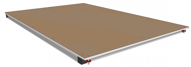
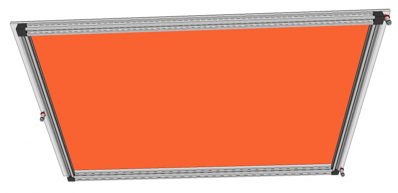
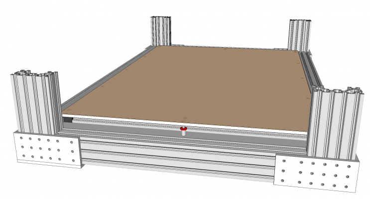
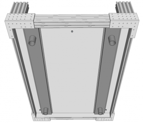
I'm building an enclosed CoreXY that will use a fixed cast aluminum plate bed with a 120v silicone heater below and PEI on top. The plate dimensions are 825mm x 558mm x 6.35mm. I'm using 3 point thumb wheel leveling for the bed and I'm debating whether or not I need a 2020 frame support for the plate as shown in the picture below. The heat bed I've ordered has 3 heating zones for different sized prints. What advice can you guys give me about expansion and deflection of a plate this size when heated? Do you think the 2020 framing screwed around the perimeter is necessary? Thanks...TP
Edited 1 time(s). Last edit at 11/29/2016 03:35PM by simspeed.
Edited 1 time(s). Last edit at 11/29/2016 03:35PM by simspeed.
|
Re: Cast tooling plate print bed flatness November 30, 2016 01:41PM |
Registered: 8 years ago Posts: 601 |
|
Re: Cast tooling plate print bed flatness November 30, 2016 01:42PM |
Registered: 10 years ago Posts: 651 |
Quote
simspeed
I'm building an enclosed CoreXY that will use a fixed cast aluminum plate bed with a 120v silicone heater below and PEI on top. The plate dimensions are 825mm x 558mm x 6.35mm. I'm using 3 point thumb wheel leveling for the bed and I'm debating whether or not I need a 2020 frame support for the plate as shown in the picture below. The heat bed I've ordered has 3 heating zones for different sized prints. What advice can you guys give me about expansion and deflection of a plate this size when heated? Do you think the 2020 framing screwed around the perimeter is necessary? Thanks...TP
[attachment 86709 Heatbeddrawing.JPG]
I'm thinking that 6.35mm is rigid enough to not have a frame of 2020 attached to it.
Plus you'd just be increasing the mass that needs to be heated.
Plan for my design would be a support frame for the bed, with teflon blocks attached in a 3 point leveling arrangement. Then bolts through the bed, with a spring into the teflon blocks.
|
Re: Cast tooling plate print bed flatness November 30, 2016 02:31PM |
Registered: 8 years ago Posts: 622 |
Quote
simspeed
I'm building an enclosed CoreXY that will use a fixed cast aluminum plate bed with a 120v silicone heater below and PEI on top. The plate dimensions are 825mm x 558mm x 6.35mm. I'm using 3 point thumb wheel leveling for the bed and I'm debating whether or not I need a 2020 frame support for the plate as shown in the picture below. The heat bed I've ordered has 3 heating zones for different sized prints. What advice can you guys give me about expansion and deflection of a plate this size when heated? Do you think the 2020 framing screwed around the perimeter is necessary? Thanks...TP
[attachment 86709 Heatbeddrawing.JPG]
That's a big bed. Personally, I'd be inclined to add the support with an extra rail across the centre to prevent it from bowing, if you can manage it. I could be wrong as I haven't done any maths - it's just a gut feeling that it's likely to bow under it's own weight without any central support. What you might need to take into account on a bed that size is thermal expansion. The maths for that is easy. The coefficient of linear thermal expansion for aluminium is about 0.00024 mm/degK (I think but best to check). So taking an extreme situation and heating the bed to 100degC above ambient (to keep the maths simple) your long edge of 825mm will expand by (825*100*0.000024 = ) 1.98mm which you ought to take into account when designing the fixing and mounting arrangement. HTH
Edited 2 time(s). Last edit at 11/30/2016 02:33PM by deckingman.
|
Re: Cast tooling plate print bed flatness November 30, 2016 03:50PM |
Registered: 10 years ago Posts: 169 |
Thanks everyone for the feedback. The 1/4" plate would be screwed to the 2020 with flush countersunk screws. The whole assembly would stand off the stainless steel table top by the 3 thumbscrew adjusters. The 2020 would act simply as bridge type trusse to minimize plate deflection along the length of the 2020. The problem for me with a center brace is the silicone heater will be stuck to the bottom side of the plate inside the 2020 perimeter frame (see drawing). A cross brace would sandwich the heater between the brace and plate which doesn't appear to be a good idea...but I could be wrong. I haven't ordered the plate yet, so I could go with a 3/8" thick plate instead of the 1/4" if there's any benefit to doing so. The linear thermal expansion is a good point that can be allowed for by slotting the holes in the stainless table top to allow the free floating adjustment screws to slide a little as the plate heats and cools. Thanks for the info on that Deckingman.
|
Re: Cast tooling plate print bed flatness December 01, 2016 03:09AM |
Registered: 9 years ago Posts: 483 |
You can calculate how much expansion the bed will have using tools on this site: [www.engineeringtoolbox.com]
I'd also recommend using socket head machine screws with a counterbore instead of countersunk flathead machine screws. The later won't allow expansion.
I'd also recommend using socket head machine screws with a counterbore instead of countersunk flathead machine screws. The later won't allow expansion.
Sorry, only registered users may post in this forum.
