Home
>
Reprappers
>
Topic
A fixed-bed gantry design
Posted by finix
|
A fixed-bed gantry design November 21, 2017 07:52PM |
Registered: 6 years ago Posts: 18 |
Hi All,
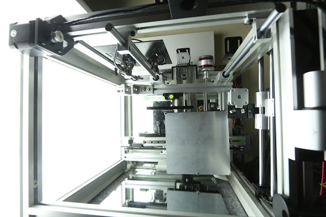
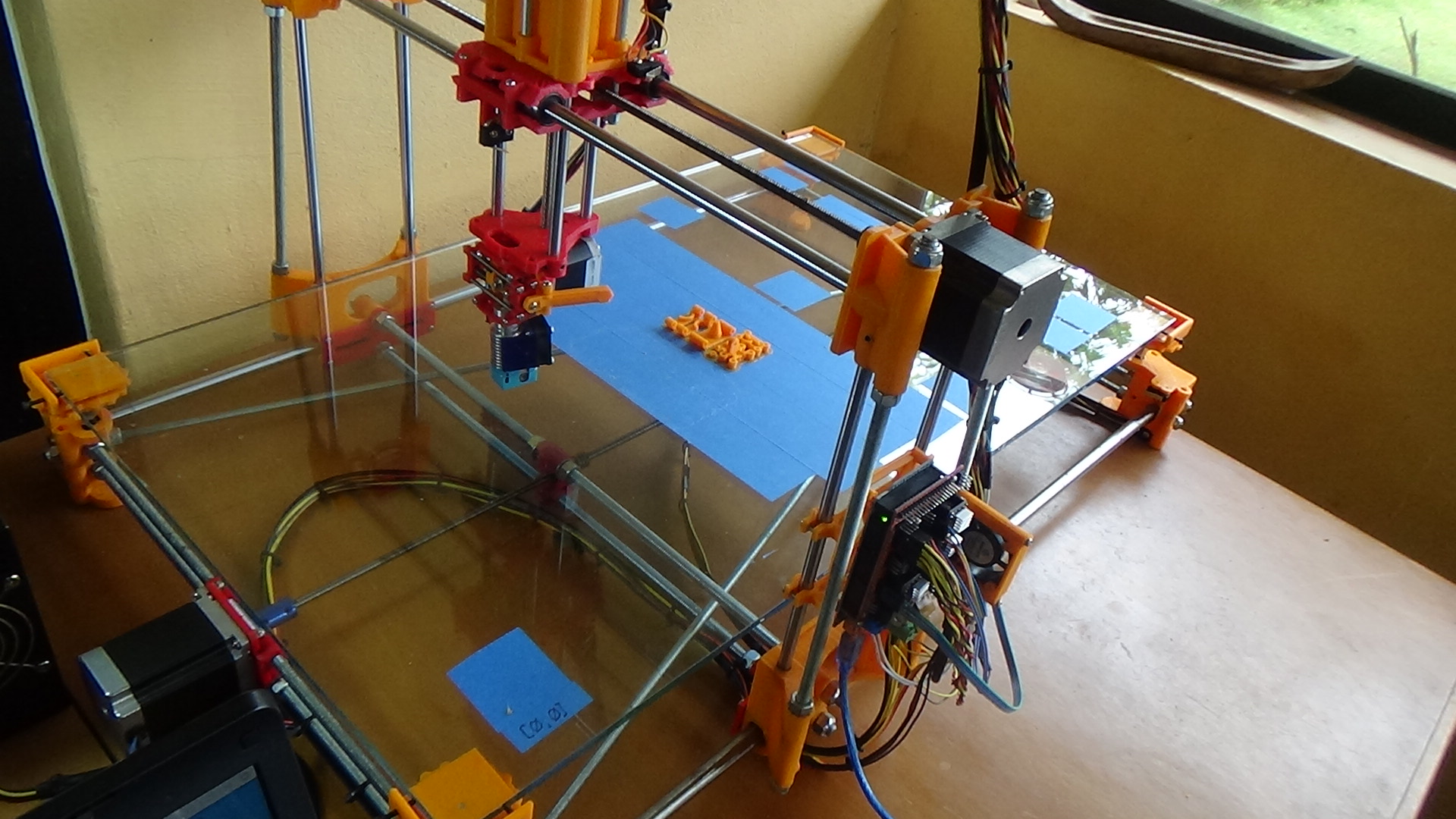
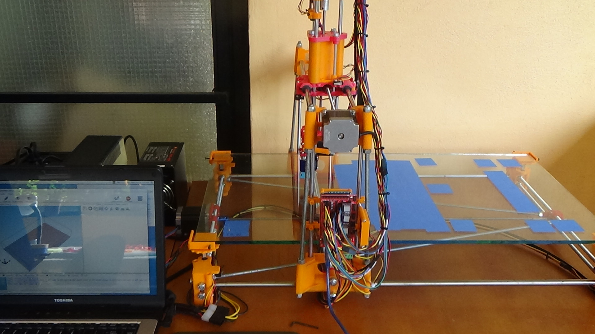
Here's a large-format fixed-workbed leadscrew-driven gantry design. I've called it the Visible Robot.
I tried to design it such that, with the exception of the needed precision pieces; e.g., motors, leadscrew/anti-backlash nut, linear bearings etc., one could print the plastic parts and run down to the local hardware store for the rest. No weldments. No fancy linear rails. The "ball-bearings" used in the bed levelers are .177" (4.5mm) BBs.
All the plastic parts for this rather large machine were printed on a tiny Printbot Jr. (135 x 115 x 100mm work-envelope). A cute photo of "child holding mother" is included.
A more complete listing of, and reasoning behind the ideas going into the machine are here.
[finixsystems.com] /2017/05/09/ideas-going-into-the-visible-robot/
Comments and questions are more than welcome.
Attachments:
open | download - DSC01285.JPG (458.6 KB)
open | download - DSC01287.JPG (347 KB)
open | download - DSC01290.JPG (370.7 KB)
open | download - DSC01292.JPG (426.1 KB)
open | download - DSC01293.JPG (496.8 KB)
open | download - DSC01296.JPG (431.9 KB)
open | download - DSC01307.JPG (470.2 KB)
open | download - DSC01311.JPG (404.8 KB)
open | download - DSC01319.JPG (289 KB)
open | download - DSC01309.JPG (452.4 KB)
|
Re: A fixed-bed gantry design November 24, 2017 03:53PM |
Registered: 7 years ago Posts: 154 |
|
Re: A fixed-bed gantry design November 24, 2017 09:42PM |
Registered: 8 years ago Posts: 1,671 |
and if something heavy falls off the gantry...
is it all 8mm rods, it looks a little too large...saggy frame saggy wibbly wobbly jelly prints on a plate.
Great for printing gummy bears
Sorry 4 takin da P... I am only jokin(hope men dont start pulling the current media sideshow "I was offended & abused")
The great thing about 3D printing is you can make whatever you want (within the confines of...)
|
Re: A fixed-bed gantry design November 24, 2017 10:23PM |
Registered: 6 years ago Posts: 18 |
Mmm, not sure what you mean about ".. something heavy falls off the gantry." Nothing goes up there but the X-Z carriages and the strand of filament that's being pulled down into the extruder.
The frame, using stiffening rods positioned in a bracing trapezoid is actually quite stiff, though clearly not as stiff as a frame completely done in metal would be. (Much as we try to fool ourselves in thinking we can beat it, Young's modulus remains the law). ;-) The idea of the design was to follow the RepRap formula of self-replication for a large-format machine--and to be able to build the machine with simple tools (no weldments).
BTW: the 'X' and 'Y' axes have a repeatability of ~ +/- .0015" as shown using a dial indicator.
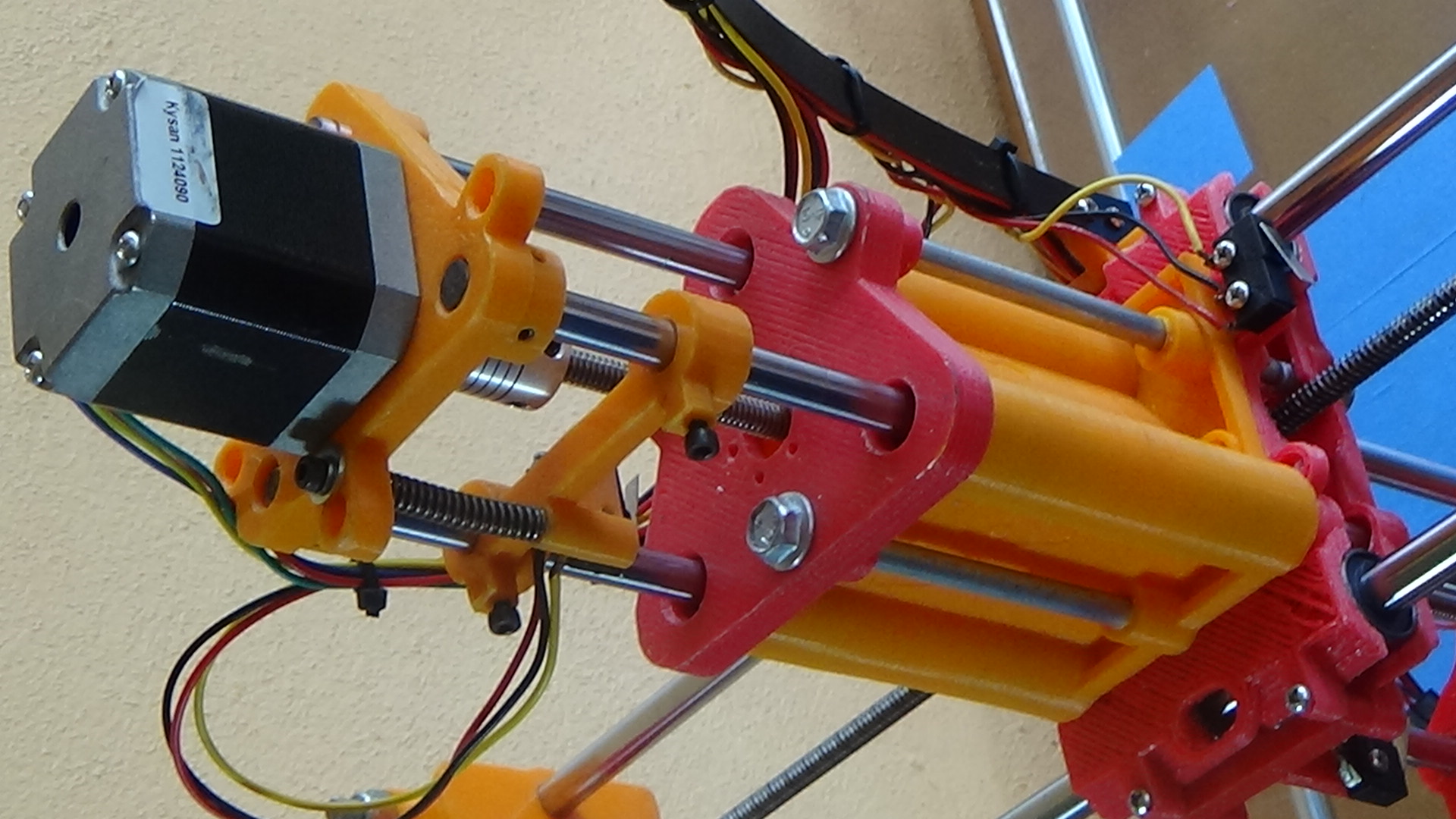
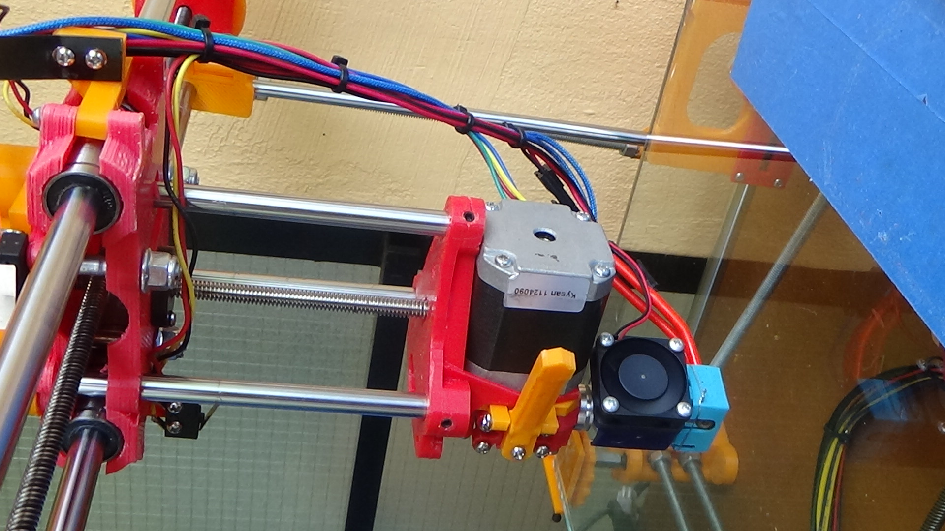
The 'Y' (long) axis uses 12mm shaft. The 'X' axis, 10mm. 'Z' axis uses 8mm.
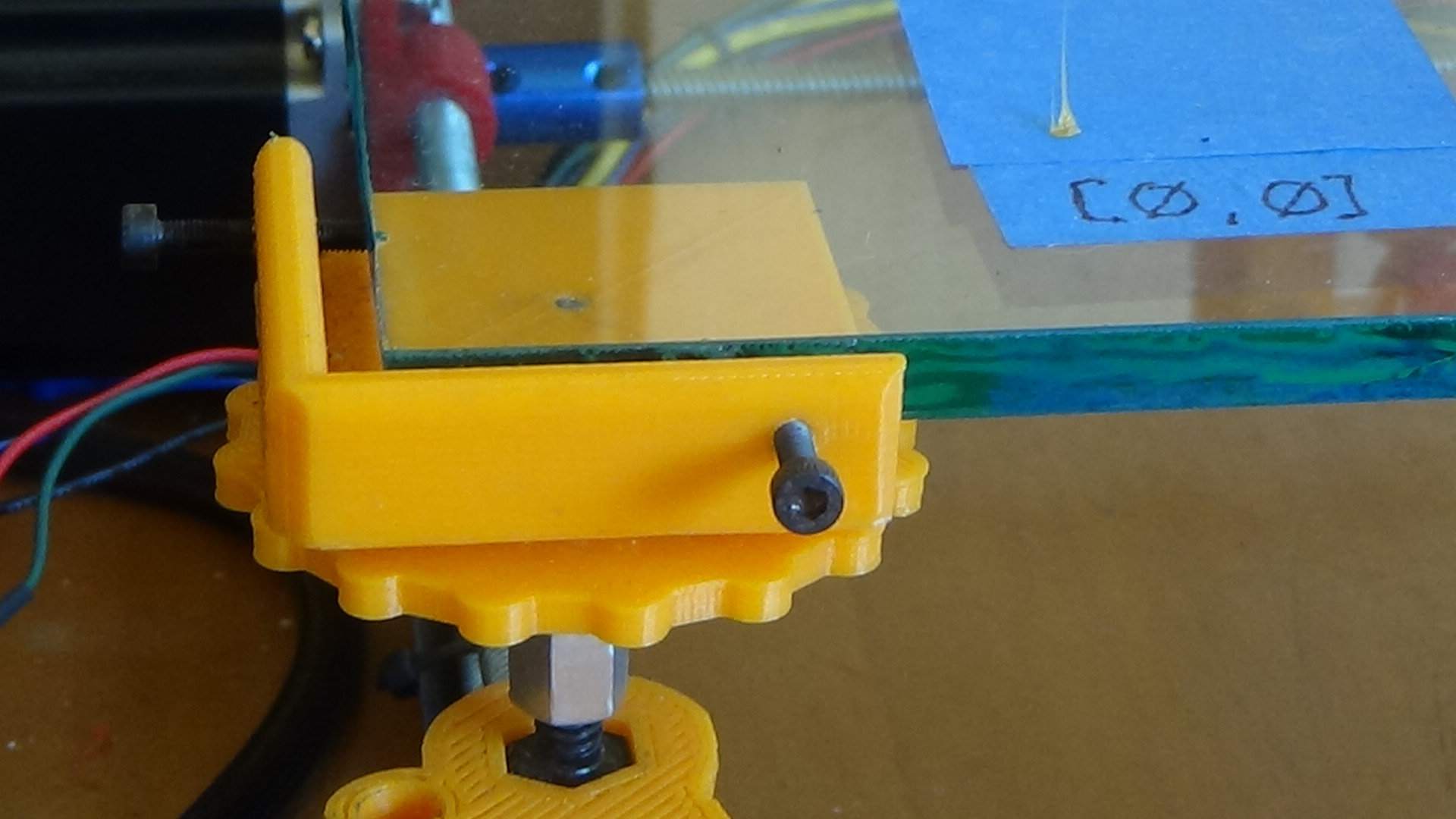
The deflection (your "sag") of the 'X' and 'Y' shafts are complemented with a very similar deflection of the 5/16" glass workbed. The tip of the hotend travels in a plane that's quite parallel to the bed, allowing printing anywhere on the bed's surface.
The frame, using stiffening rods positioned in a bracing trapezoid is actually quite stiff, though clearly not as stiff as a frame completely done in metal would be. (Much as we try to fool ourselves in thinking we can beat it, Young's modulus remains the law). ;-) The idea of the design was to follow the RepRap formula of self-replication for a large-format machine--and to be able to build the machine with simple tools (no weldments).
BTW: the 'X' and 'Y' axes have a repeatability of ~ +/- .0015" as shown using a dial indicator.
The 'Y' (long) axis uses 12mm shaft. The 'X' axis, 10mm. 'Z' axis uses 8mm.
The deflection (your "sag") of the 'X' and 'Y' shafts are complemented with a very similar deflection of the 5/16" glass workbed. The tip of the hotend travels in a plane that's quite parallel to the bed, allowing printing anywhere on the bed's surface.
|
Re: A fixed-bed gantry design November 25, 2017 03:07PM |
Registered: 8 years ago Posts: 1,671 |
Wow perfectly sync'd warp of glass & rods....though the rods i'm talking about are the H/X ones, and the bed looks like it would flex in Y more, I assume your X- Z plunger cant extend lower than glass avoiding calamity, and you probably made it on such a way that nothing would fall off...but that does have some heavy looking stuff there, if one rod came loose that would do it, but you might have done something to stop this, is see grubscrews in the plastic etc but i'm just cautious and wouldnt trust plastic for this...but you must know what your doing. so if the repeat-ability is as you say what happened with the prints?
|
Re: A fixed-bed gantry design November 27, 2017 07:19AM |
Registered: 7 years ago Posts: 507 |
It seems like what you have configured is similar to the H style gantry most replicator clones/coreXY etc use, except with the x gantry on stilts and a head that plunges in the z axis. Why not move the y axis up above the bed as well and connect the x axis straight to it?
Nice to see some more stationary bed cartesian printers out there, I'm looking to build a large format printer myself and don't want to move the bed so I'm looking at something similar.
Nice to see some more stationary bed cartesian printers out there, I'm looking to build a large format printer myself and don't want to move the bed so I'm looking at something similar.
|
Re: A fixed-bed gantry design November 28, 2017 08:53PM |
Registered: 6 years ago Posts: 18 |
Hi Trakyan,
Conceptually, the Visible Robot was intended to be the base machine for a desktop manufacturing workcell.
I wanted the periphery to be open, so as to be able to allow maximum space for a parts-presentation carousel or conveyor, also a rack of some sort where tools could be made available to a robot-mounted auto-tool-changer. (This alpha-level design is at finixsystems.com/product/atc-auto-tool-changer).
I also wanted to allow the design to be build inexpensively by someone with only rudimentary tools. To me, this meant no weldments, and no expensive extruded aluminum parts.
To be sure, your suggestion will eliminate the pendulum-within-a-pendulum problem. The mechanical challenge is to make the gantry as stiff as possible, given that plastic is holding the rigid parts together. In an attempt to do this, I had each of the metal parts forming the X-Y frame and the gantry in contact with one another. So it's metal-to-metal-to-metal, there. I certainly won't claim this is as stiff as an all-metal frame, but given the design's conceptual constraints, it holds together and moves quite well.
|
Re: A fixed-bed gantry design November 30, 2017 01:52PM |
Registered: 11 years ago Posts: 1,049 |

|
Re: A fixed-bed gantry design November 30, 2017 10:02PM |
Registered: 6 years ago Posts: 18 |
@cozmicray
Both X and Y axes use two shafts. The Z axis uses three.
Seems you've read it wrong. The glass _thickness_ is 5/16".
Regarding "sag", of which there is little, due to the weight of both glass and shafting. Conceptually, both are beams supported at their ends. (BTW: Even plate steel would have sag [though less] due to the same thing--its weight).
What we care about is the difference between the planes of the glass surface and the plane the tip of the nozzle makes as it moves above the entire workbed. In order to print anywhere on the surface, this difference--anywhere on the workbed--should be less than the height of the first layer of plastic, which it is. There's no need to replace the glass with aluminum. The glass plate works just fine.
As I mentioned to Trakyan, above, the design is intended to be a base for a desktop manufacturing workstation. To this end, I wanted it open-sided and open-ended to be able to fit parts-presentation and tool-presentation devices at its periphery. I also wanted it able to be built with few tools and without sophisticated (costly) parts; e.g., extruded aluminum beams.
A fuller list of the designs advantages is at [finixsystems.com] /docs/visual-robot-features/
|
Re: A fixed-bed gantry design December 01, 2017 09:25AM |
Registered: 8 years ago Posts: 1,671 |
You have a pic with multiple gantries on the rails are they all 12mm rails & 8mm threaded?
I would be worried that the thing might shake itself to bits, I've never had a prusa with threaded rods so dont know how good it can be.
The reason I bought 3 fidget spinners recently was not for fidgeting, but to test out a similar arrangement as the triple rod setup you have, cheaper than getting them made on shapeways.
Edited 2 time(s). Last edit at 12/02/2017 03:30PM by MechaBits.
|
Re: A fixed-bed gantry design December 04, 2017 07:52PM |
Registered: 6 years ago Posts: 18 |
The photo 'base4.219.jpg' looks very solid. Did you put it to work after what I take to be the infinity mirror? Doing what?
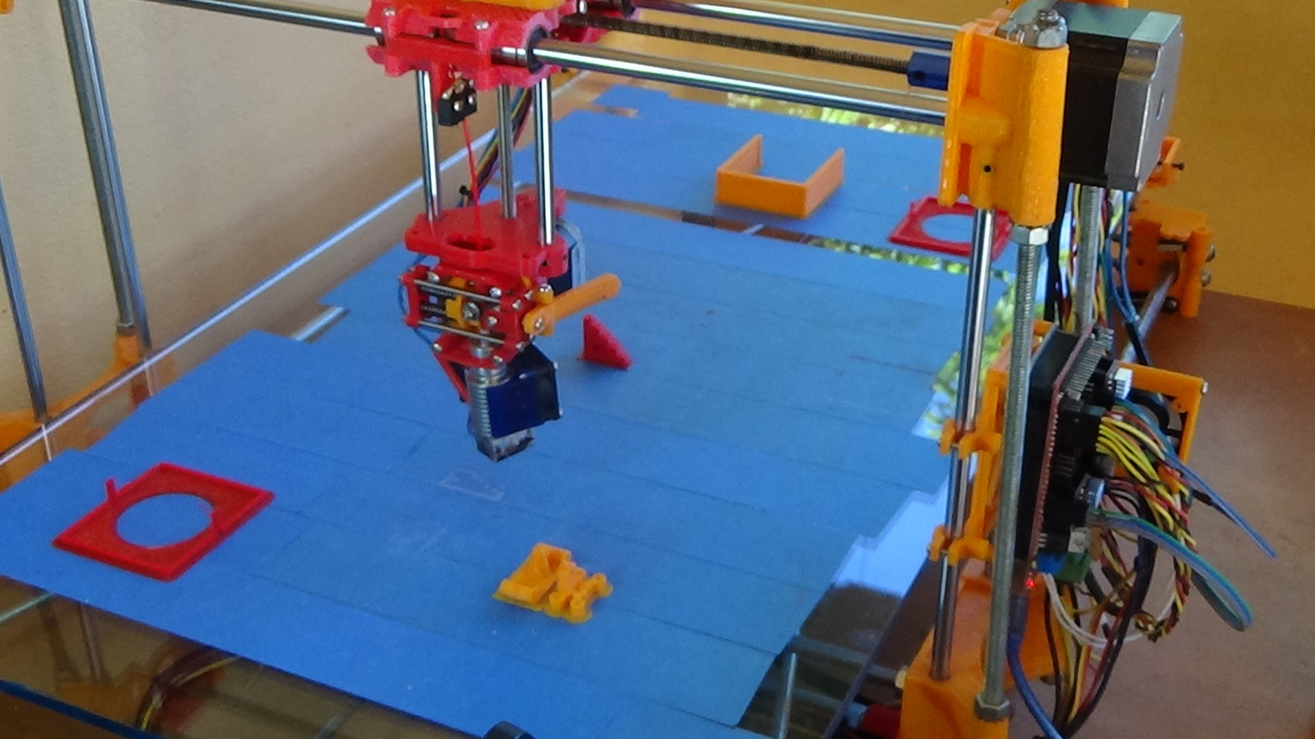
The last photo has a motor-driven gizmo driven in Z by a bottom mounted motor. It does look quite heavy. What's the gizmo do?
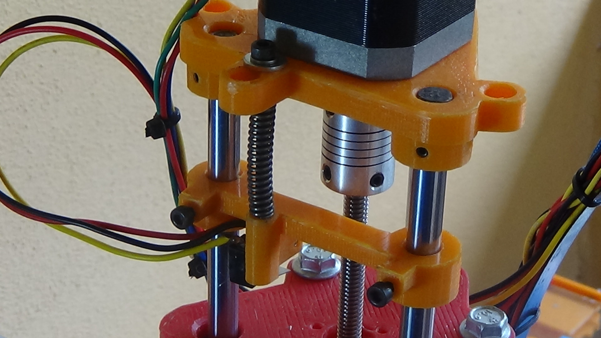
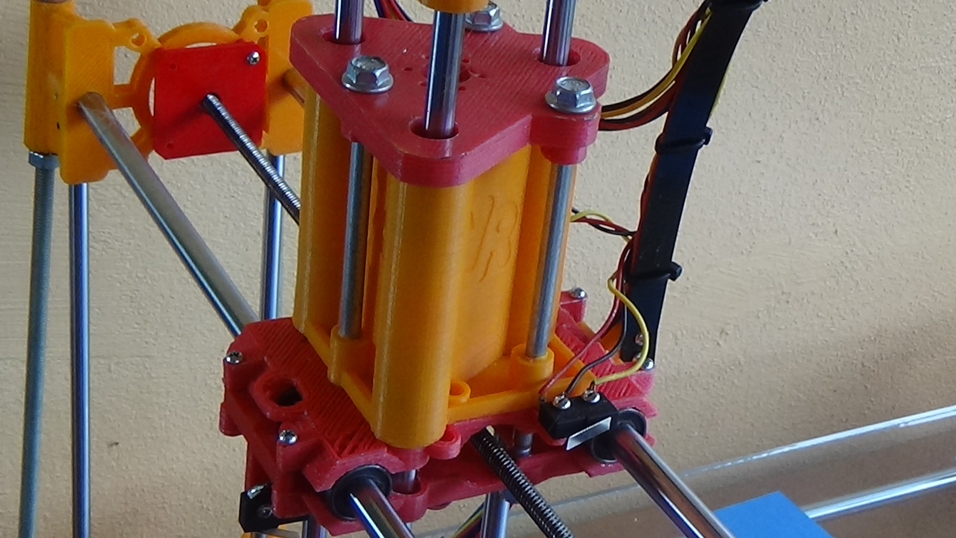
I tried to mitigate the pendulum action of the Z axis mechanism by using a third shaft. Inasmuch as I had no two rail mechanism to compare it with I can't know whether it helped or not. I just assume it did.
There seems to be two more axes down below, one of them belt-driven. Purpose?
The last photo has a motor-driven gizmo driven in Z by a bottom mounted motor. It does look quite heavy. What's the gizmo do?
I tried to mitigate the pendulum action of the Z axis mechanism by using a third shaft. Inasmuch as I had no two rail mechanism to compare it with I can't know whether it helped or not. I just assume it did.
There seems to be two more axes down below, one of them belt-driven. Purpose?
|
Re: A fixed-bed gantry design December 06, 2017 07:40PM |
Registered: 8 years ago Posts: 1,671 |
I didnt post pics of the infinity cube mirror version, no longer a render (will dig them out if your interested, but it was just a series of machine clones in a line, with some mirrors to add more), the other pic not render gizmo, was Rather than hang the Z actuator from the X, I had the whole X move in Z from one central point, so it would hang but not have to move. Purpose 3D printing(a clue was in the hotend).
I was thinking of hanging my ZX on a Y track so my pendulum effect would be in Y where yours is possibly in X?
I've just completed a gantry for it, well for something else but now i've discovered how stiff it seems I think it could be up to the job.
Edited 5 time(s). Last edit at 12/07/2017 01:07PM by MechaBits.
(will dig them out if your interested, but it was just a series of machine clones in a line, with some mirrors to add more), the other pic not render gizmo, was Rather than hang the Z actuator from the X, I had the whole X move in Z from one central point, so it would hang but not have to move. Purpose 3D printing(a clue was in the hotend).I was thinking of hanging my ZX on a Y track so my pendulum effect would be in Y where yours is possibly in X?
I've just completed a gantry for it, well for something else but now i've discovered how stiff it seems I think it could be up to the job.

Edited 5 time(s). Last edit at 12/07/2017 01:07PM by MechaBits.
|
Re: A fixed-bed gantry design December 09, 2017 09:39AM |
Registered: 7 years ago Posts: 47 |
Nice design. thats some insane print volume.
Not here to take a Piss or anything, I too enjoy designing my own unique frames.
I would use some thicker threads for the Y axis ( the one below the glass.) and thicker rods for the M10 ones you have perpendicular to the leadscrew.
You can also attach several heatbeds underneath the glass, and make like a box frame to cover yout printer to print abs.
Also love the wooden one in the last picture
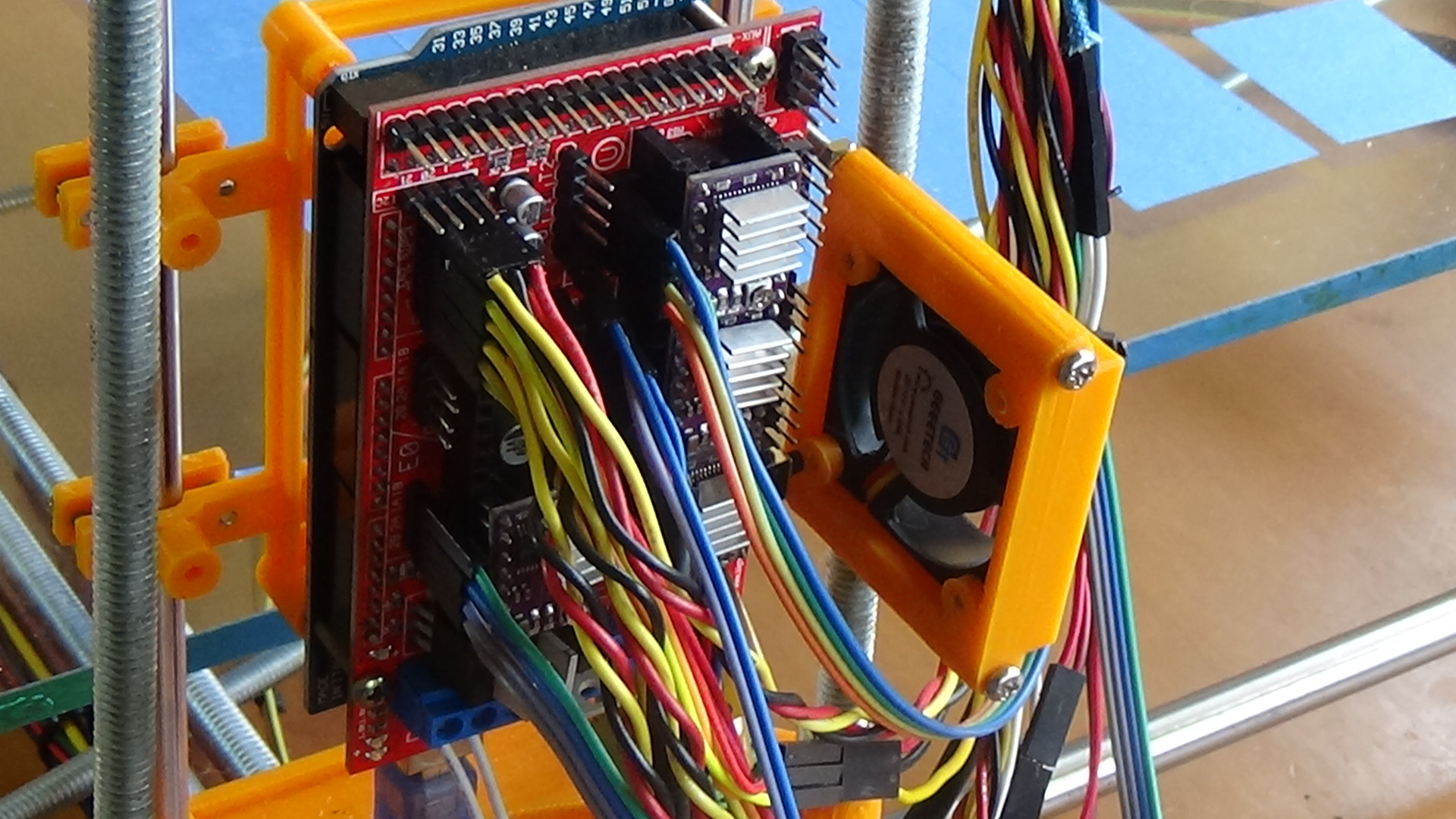
P.S> how do you have endstop wires bunched up with your stepper wires? For me it always causes some interferance leading to making homing usless.
Not here to take a Piss or anything, I too enjoy designing my own unique frames.
I would use some thicker threads for the Y axis ( the one below the glass.) and thicker rods for the M10 ones you have perpendicular to the leadscrew.
You can also attach several heatbeds underneath the glass, and make like a box frame to cover yout printer to print abs.
Also love the wooden one in the last picture
P.S> how do you have endstop wires bunched up with your stepper wires? For me it always causes some interferance leading to making homing usless.
|
Re: A fixed-bed gantry design December 09, 2017 05:28PM |
Registered: 9 years ago Posts: 483 |
Quote
finix
The deflection (your "sag") of the 'X' and 'Y' shafts are complemented with a very similar deflection of the 5/16" glass workbed. The tip of the hotend travels in a plane that's quite parallel to the bed, allowing printing anywhere on the bed's surface.
In other words the bottom surface of the print will follow the surface of the bed which is not flat (or planar). I think this will be fine for Yoda heads.
|
Re: A fixed-bed gantry design December 09, 2017 08:29PM |
Registered: 6 years ago Posts: 18 |
Good point on the thicker diameter 'Y' axis. I agree that the thinner leadscrew might be adding to some "wobble" I've seen with the gantry.
Not using a heated bed on this machine has made me re-evaluate the need. I'm coming to think that the blue painters tape works every bit as well, without the complication of "something else to go wrong and fix." (I do end up replacing rows of tape. But I've recently had a hotend slice through the kapton tape of the heated bed on my Printrbot Simple Metal). I have two other machines with heated beds. I just wonder if that (the heated bed, not the printer) was money well spent.
The wooden machine--a Printrbot Jr. V1--was the "mother" of the much larger Visible Robot. Cute, huh?
|
Re: A fixed-bed gantry design December 09, 2017 08:37PM |
Registered: 6 years ago Posts: 18 |
The tip of the hotend largely follows the deflection of the workbed--the glass. It's not perfect. At certain points (generally, the middle of the bed) the tip is closer to the bed at the ends its a bit further away. But still, filament makes contact anywhere--even if squished nearly flat toward the middle.
What seems to be happening is the metal shafts have a very slightly larger deflection at the center of travel than deflection of the glass.
What seems to be happening is the metal shafts have a very slightly larger deflection at the center of travel than deflection of the glass.
|
Re: A fixed-bed gantry design December 10, 2017 01:16AM |
Registered: 8 years ago Posts: 1,671 |
Now if you could have bed bent the opposite way to print warp that would be cool.
I thought glass wasnt suspended in the middle but supported at the ends, maybe its supported all round,
but if you added 2 level screws either side in middle you could adjust sag,
but you say it sags at the ends, so would possibly need 4 level points then.
I thought glass wasnt suspended in the middle but supported at the ends, maybe its supported all round,
but if you added 2 level screws either side in middle you could adjust sag,
but you say it sags at the ends, so would possibly need 4 level points then.
|
Re: A fixed-bed gantry design December 11, 2017 04:59PM |
Registered: 9 years ago Posts: 465 |
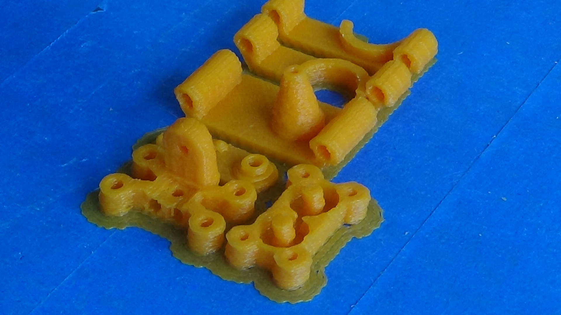
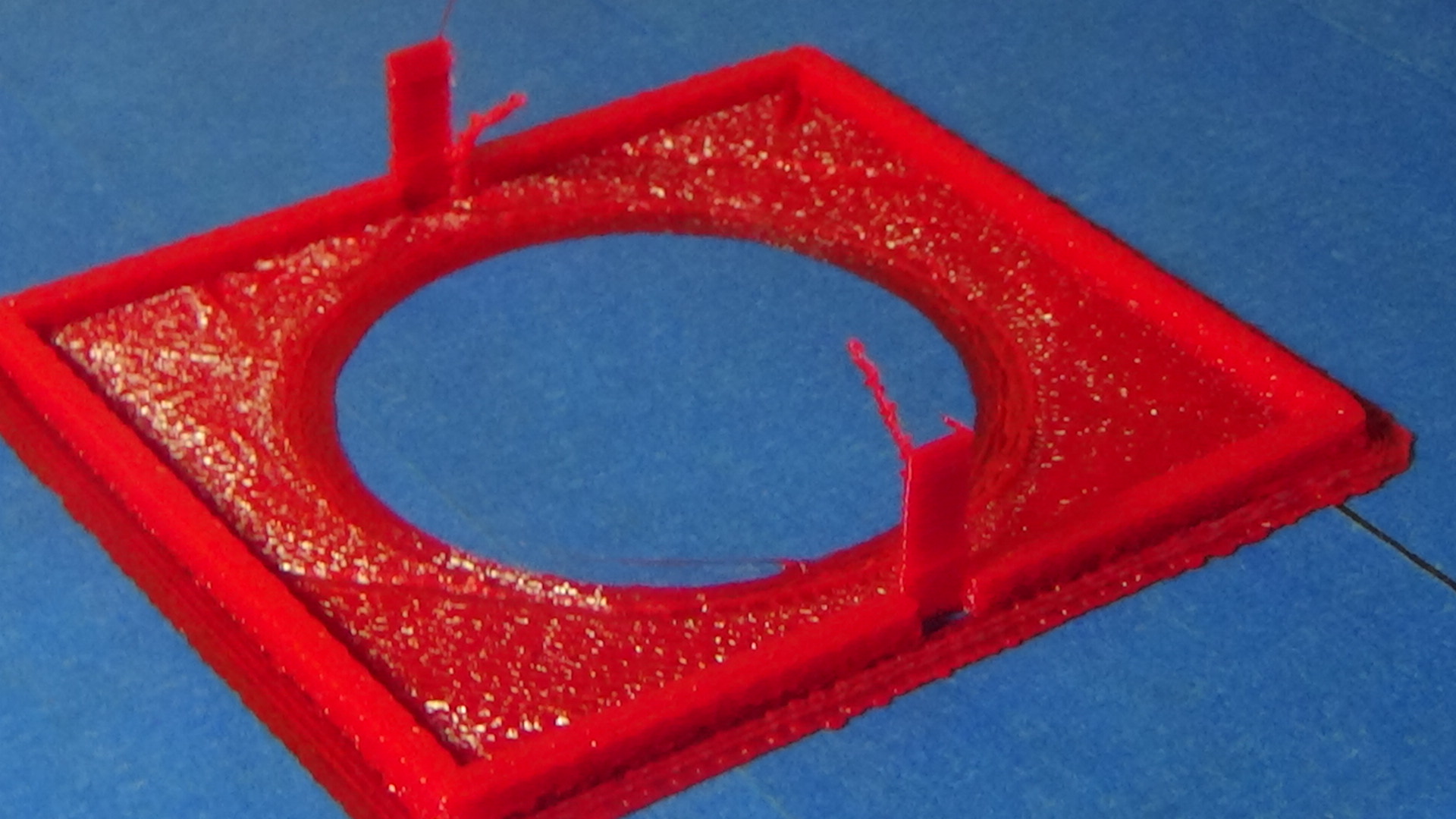
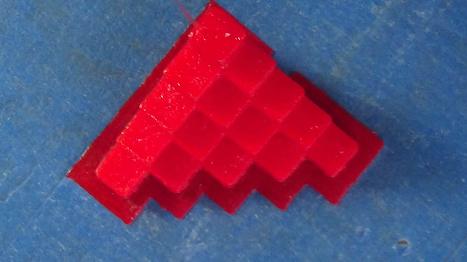
I like the idea, but as stated above, I'd be concerned about the print quality shown in DSC1287.JPG
I didn't see any other print quality samples on your website, either.
MBot3D Printer
MakerBot clone Kit from Amazon
Added heated bed.
Leadscrew self-built printer (in progress)
Duet Wifi, Precision Piezo parts
I didn't see any other print quality samples on your website, either.
MBot3D Printer
MakerBot clone Kit from Amazon
Added heated bed.
Leadscrew self-built printer (in progress)
Duet Wifi, Precision Piezo parts
|
Re: A fixed-bed gantry design December 11, 2017 06:13PM |
Registered: 11 years ago Posts: 5,780 |
The design is a variation of the classic double-pendulum, with the resulting print quality of an extruder nozzle that is swinging chaotically.
The precision number previously quoted was probably a static value, measured after all the motion has died out. Unfortunately, 3D printers are dynamic systems and the extruded plastic records the dynamic behavior, not the static behavior.
Ultra MegaMax Dominator 3D printer: [drmrehorst.blogspot.com]
|
Re: A fixed-bed gantry design December 11, 2017 07:49PM |
Registered: 6 years ago Posts: 18 |
@mechabits
I think the point is that at the layer height of the prints done, sag hasn't been a problem (except that in the middle it's been a bear getting prints off the bed).
Frankly, I only late-in-the-game considered that there might be a problem with the hotend tip travelling in the same plane as the glass bed. I have to admit to being lucky, rather than claim "it was all in the plan" to have the two planes match so closely. I'll take a bit of luck when it comes around, thank you very much. ;-)
|
Re: A fixed-bed gantry design December 11, 2017 08:08PM |
Registered: 6 years ago Posts: 18 |
@supraguy
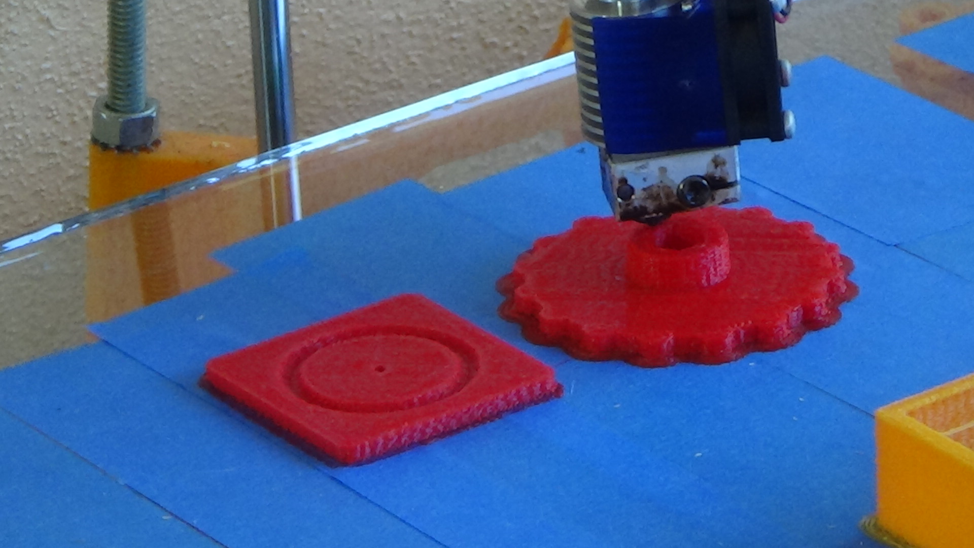
I did a bit of work in configuration to get somewhat better print quality. Photos attached.
Gotta believe, though, that given the large footprint and the fact that what holds the bits together is plastic (two orders of magnitude less stiff than most metals), the print quality will never make it to an art show--or be as good as the same machine with metal holding the bits together. Nor be as good as a smaller machine using plastic as this one does.
That said, the focus taken has been to produce parts suitable for use in a desktop machine tool, while trying to be true to the RepRap model of being able to clone itself.
|
Re: A fixed-bed gantry design December 11, 2017 08:32PM |
Registered: 6 years ago Posts: 18 |
@digitaldentist
The machine does show some double-pendulum characteristics.as I pointed out to Trakyan, above. I suppose I'd quibble with the term "chaotically," and rather use "harmonically." ;-) (The mathematician could probably determine which harmonic. The chaoticist (?) would be dismayed by the order displayed by the nozzle).
You're quite right on the repeatability measurement being taken statically. The only instrument I had to use were dial indicators, with which the 'X' and 'Y' axes were measured in both directions, coming (+X, +Y) and going (-X, -Y). Too, the measurements were done on each axis separately, meaning no combined XY movements were measured. Several repetitions were done and averaged.
|
Re: A fixed-bed gantry design December 11, 2017 09:37PM |
Registered: 6 years ago Posts: 18 |
@mechabits
Yes. The rails are 12mm on the Visible 3Bot. Same as on the single gantry Visible Robot. The threaded rods are 5/16" (quite close to 8mm).
Regarding the use of setscrews in the plastic, they actually work quite well as long as there's a shell around them. I drill the boltholes for the setscrews out to 2.5mm--essentially becoming a locknut, to hold securely. This, as opposed to drilling out to 7/64", which I use for 3mm screws that don't need to hold metal in place.
(Not to be defensive, but the machine has run for hours and hours without shaking anything loose). That said, if you look at the platform holding the (immodestly titled) Finix Extruder to the Z axis shafts, you'll see I replaced 3mm setscrews with 4mm. I had to increase the infill percentage too, as the setscrews were causing layer de-lamination.
Not to get off-topic, but could you say more about how you're using the fidget spinners with your 3-rod design?
|
Re: A fixed-bed gantry design December 12, 2017 01:12AM |
Registered: 8 years ago Posts: 1,671 |
Well they are not in use at the mo, and possibly never will be, maybe something small, but my first printer had 4x 8mm rods for the Z, and at one point I wanted it to be 3(and lead for the center). Now I knew I couldnt use the spinners for what i had in mind, but as they where injection molded(but with slight flex) I thought ya never know get em while they are cheap...pity 12mm linear bearings are 21mm not 22mm, So it could be used to anchor top & bottom of a 3 rod setup(though no real way to lock onto rods except glue, (they where really bad bearings I thought at least i'd get a few useful bearings) but they aren't linear bearings so wouldnt be much good for the moving part unless I can mod or pad it...and there's no additional useful holes for mounting anything, so more alterations, but my fallback position was for some kind of spool roller.
you've seen the printer/router that uses normal round bearings in Z cant remember the name or i would have linked the pic
.
Edited 4 time(s). Last edit at 12/12/2017 10:21AM by MechaBits.
you've seen the printer/router that uses normal round bearings in Z cant remember the name or i would have linked the pic
.

Edited 4 time(s). Last edit at 12/12/2017 10:21AM by MechaBits.
|
Re: A fixed-bed gantry design December 12, 2017 11:52PM |
Registered: 7 years ago Posts: 507 |
|
Re: A fixed-bed gantry design December 13, 2017 12:35AM |
Registered: 8 years ago Posts: 1,671 |
|
Re: A fixed-bed gantry design December 13, 2017 09:24PM |
Registered: 6 years ago Posts: 18 |
|
Re: A fixed-bed gantry design December 13, 2017 11:08PM |
Registered: 7 years ago Posts: 507 |
It's a crossed axis gantry design, similar to the ultimaker, it's just the other crossing rail is really far back (and the angle the photo was taken from doesn't help) and looks like a part of the perimeter rails in that photo. Look around google images for MPCNC and you should get a better idea of what I mean, I'm not sure I explained it well.
|
Re: A fixed-bed gantry design December 14, 2017 08:44PM |
Registered: 6 years ago Posts: 18 |
Sorry, only registered users may post in this forum.