Home
>
Reprappers
>
Topic
Steampunk extruder feasible?
Posted by o_lampe
|
Steampunk extruder feasible? December 08, 2017 09:59AM |
Registered: 8 years ago Posts: 5,232 |
Hi guys,
I'm a big fan of steampunk and I have lots of these small, light linear actuators laying around from old DVD drives. So I thought, I could make a steampunk extruder with two of the steppers.
The hobbed hub would be a crankshaft with two arms in 90° angle. Each arm is moved by one stepper. To keep it simple, I don't want to use con rods, but pivot the stepper itself.
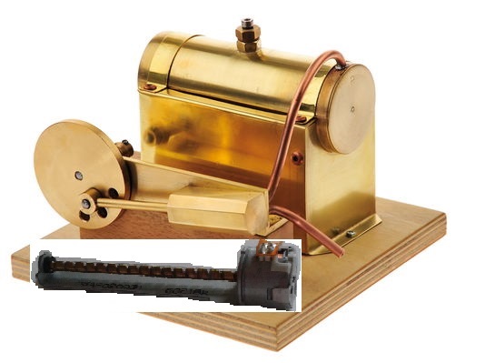
I made a little photoshop how a single stepper would be attached. The flywheel would be the crankshaft. The second stepper would be placed on the other side of the crankshaft. The steam engine is just a sample, how a simple con-rod less linear_to_rotation translation looks like.
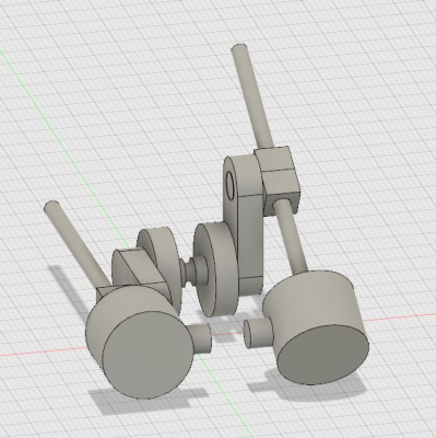
edit: just made a "scale" model of the 90° crankshaft w. two steppers. I hope you get the idea?!
With the arms in 90°angle, both steppers would keep the crank turning. Their torque would sum up like sin(angle A )+ cos (angle B ).
IMHO torque would be constant.
The question is, how difficult would it be, to control both steppers? Would it require a separate controller or could I use two onboard drivers and rewrite firmware?
I could use some help with that....
Another point is the nuts for the leadscrew: I'd like to make them from Delrin, but how would I cut the thread?
I could replace the original lead screw with a common M3 rod and use thread cutters then. The torque and resolution would be much higher ( pitch is now 3.2mm/turn ), but retractions might be a little slow then.
Your honest opinions?
Edited 5 time(s). Last edit at 12/08/2017 02:12PM by o_lampe.
|
Re: Steampunk extruder feasible? December 08, 2017 03:38PM |
Registered: 8 years ago Posts: 601 |
There are delrin leady screw nuts out there that you can buy. Most notably are the openbuilds ones around £10 each. You can also buy them from more expensive companies, and I'm sure China have them.
With your unique plan though, you may want a custom nut to stay in keeping with the design. I've seen people make these by heating up the screw and then melting two blocks of delrin onto it. The result is then cleaned up on a lathe.
Interestingly, you can buy hand taps for lead screws! Just did a quick Google and found them on ebay for about £10. This is certainly the easiest if you don't have a lathe.
|
Re: Steampunk extruder feasible? December 08, 2017 08:08PM |
Registered: 8 years ago Posts: 1,671 |
|
Re: Steampunk extruder feasible? December 09, 2017 02:17AM |
Registered: 8 years ago Posts: 5,232 |
Cog wheels are classic.but I don't see a reason to add some. Maybe an old handwheel to tighten the idler bearing arm?
Thanks for the hints about melting Delrin. I might try to cut/melt a thread through a preheated block with the original screw. This stuff is so cheap....
I might want a nut with a slot at the side. That way it could be repositioned easier
About firmware control: It dawned me, that the "arc" moves G2 & G3 are already implemented. Now they have to be refined to work with extruder commands.
Start and stop position, acceleration, synchronization and all that stuff is beyond my horizon. I only have the vague idea, that the end position has to be stored in Eeprom ( or on SD-card ) when the enable signal of the extruder driver switches the driver off ( M84 ). Otherwise, the extruder wouldn't restart. ( Especially after a power cycle )
|
Re: Steampunk extruder feasible? December 09, 2017 03:41AM |
Registered: 8 years ago Posts: 5,232 |
I made some calculations:
IIRC the steppers have 48 steps/turn. The lead screw length allows 30-40mm travel (+10mm nut length). I took 7.5mm dia for the hobbed gear.
Then e-steps with 30mm crankshaft would be ~245steps/mm ( full steps ). That's a gear ratio of 5:1. The steppers can take 150mA. It looks like the torque might be a bit to low for fast prints or small nozzles. With 40mm crankshaft, the ratio would be 6.8:1. Much better....definitely worth a try.
Edited 1 time(s). Last edit at 12/09/2017 03:41AM by o_lampe.
|
Re: Steampunk extruder feasible? December 09, 2017 08:00PM |
Registered: 8 years ago Posts: 1,671 |
Cogs or wheels with teeth of choice to increase torque somewhere or show. Can the piston be driven with 2 rods, isnt there a flat spot would it lock i cant say ive seen it but perhaps you can, but on some bikes they have of center cranks to help cant you have a linear thing driving a cog which goes to another to get what you want?
|
Re: Steampunk extruder feasible? December 13, 2017 04:02PM |
Registered: 8 years ago Posts: 5,232 |
I tried to write a small program to find a way how I could synchronize two steppers to drive one crankshaft rotating with constant speed.
I started with a basic version: one stepper running through the first quadrant. I think, I have the math sorted out, but the timing is wrong. Especially when I add microsteps.
My basic strategy is to calculate the time gap between single steps, which varies with the cos of the crankshaft angle. The first steps are slow and calculation seems accurate, but the faster the stepper has to run, the less accurate the calculations are ( smaller angle difference ). Even when I run the code on a Arduino Due instead of Atmega2560 it can't keep up.
Is it the Arduino IDE, thats so slow? I know float variables are a PITA for 8bit, but the Due doesn't change it much. I also don't have a clue, how to calculate acos arcs/angles with integer...
There must be a totally different strategy, I didn't think off. Can someone with more insight give me a hint?
THX
Edited 1 time(s). Last edit at 12/13/2017 04:03PM by o_lampe.
|
Re: Steampunk extruder feasible? December 21, 2017 02:54AM |
Registered: 8 years ago Posts: 5,232 |
It seems I couldn't gain enough interest in my little project...
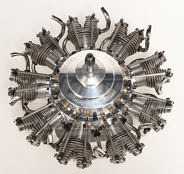
So what about another teaser: Radial engine, steampunk style
The steppers already look like pistons. The leadscrew nut would be fixed to the crank-housing and the steppers would bob up and down.
There would be two smooth rods to guide one piston, but they would also look like external cam-pushrods.
We could even make them move to push some fake rocker arms with small springs...
The back could be open to see the pushrods and crankshaft move.
Such a thing would be a nice desktop gadget.
All we need is a working software to drive 5 steppers moving in sync for a 72° crankshaft angle.
Edited 1 time(s). Last edit at 12/21/2017 02:58AM by o_lampe.
|
Re: Steampunk extruder feasible? December 21, 2017 07:44AM |
Registered: 7 years ago Posts: 507 |
For the radial engine, and this is just a suggestion, why not try solenoids? they behave a bit more like pistons and might be easier to control. To me it's also a bit cooler since it's converting reciprocating motion to rotary and not rotary->linear/reciprocating->rotary which personally feels a bit redundant (I know this isn't meant to serve some grand purpose, it just seems to bug me on a fundamental level). There are also some starting points for solenoid engines around the internet.
Other steam punkish ideas: have you looked at sterling engines? I find them quite cool. Anyways, correct me if I'm wrong but isn't steampunk supposed to avoid electricity? I find that part quite intriguing since I like mechanical solutions to things. At some point in the future I'm looking to put together a mech/stilt suit that is entirely passive/powered by the person inside.
Other steam punkish ideas: have you looked at sterling engines? I find them quite cool. Anyways, correct me if I'm wrong but isn't steampunk supposed to avoid electricity? I find that part quite intriguing since I like mechanical solutions to things. At some point in the future I'm looking to put together a mech/stilt suit that is entirely passive/powered by the person inside.
|
Re: Steampunk extruder feasible? December 22, 2017 02:30AM |
Registered: 8 years ago Posts: 5,232 |
Maybe the term steampunk is wrong. I just wanted to point out, that I try to use oldskool techniques with modern parts. Lets call it Retro-style.
The main reason, why I want to use the steppers is, I have plenty of them laying around waiting for a project.
The solenoid idea isn't bad either, we could implement a cam shaft, which controls a set of switches for the solenoids.
But I wouldn't want to have such a model on my desktop. Imagine the bang-bang sound it would make, compared to the whisper of steppers.
Edited 1 time(s). Last edit at 12/22/2017 02:32AM by o_lampe.
|
Re: Steampunk extruder feasible? December 22, 2017 06:26AM |
Registered: 7 years ago Posts: 507 |
Sorry, only registered users may post in this forum.


