Home
>
Reprappers
>
Topic
Beltless I3 project, feedback?
Posted by SupraGuy
|
Beltless I3 project, feedback? January 11, 2018 02:14PM |
Registered: 9 years ago Posts: 465 |
My I3 has always been something of a POS. For whatever reason, I've never been happy with the steps/mm settings, I even changed out the belts, because I had thought that they stretched at some point. Even with new belts, getting the steps/mm sorted was never good. Even when it was good, I'd get results where circles weren't circular. I thought that my stepper motors might be going weird, and replaced those. Still no better. The same steppers on another project worked fine.
So, I've started over.
I have another printer, which works beautifully, but doesn't have a heated bed. Printing in anything other than PLA is an exercise in futility. I'll be adding an HBP to it very soon, but in the meantime, I want to make my I3 useful, so I decided to go beltless.
The original one used 5mm threaded rod for the Z axis, which I never had a problem with, other than that it was kind of slow. I decided to keep the Z axis rods, since the very high resolution with a 0.8mm thread pitch (At 200 steps/rotation, plus 16X microstepping giving me 4000 steps/mm) has never resulted in anything like Z wobble problems, no matter what I choose as a layer depth. Or at the very least, I never noticed. In any case I decided to keep that.
The Y axis had been a constant source of headaches since day 1. I have never been happy with the belt holder. I had a redesign/rebuild which was better, but still not great. I changed the belt holder to hold and anti-backlash nut, and changed the motor holder.
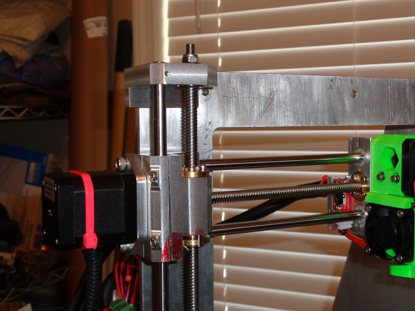
I've changed that again, since then. That version was prone to crushing, so the new version has solid braces on the threaded rod, the nut holder is the same though. I was going to include and end-stop holder on the motor end, but I decided to leave that on the other end, since that (Part of my older redesign while I was still belt driven) has always worked quite well. I'm sure that I could have integrated the endstop as well, and I may still do that in order to clean up the wiring a little, just to have the endstop wiring in a harness with the motor wires. I also realized that enclosing the coupler portion meant that I needed to have the T8 leadscrew attached to the motor before installing the motor in the mount. Not too bad, but makes assembly more complicated than it needs to be, so I opened that up after making the braces, at least enough to get to the set screws.
The X axis posed more challenges. The carriage is a little further from the Z rods than I'd ideally like. I've got this set up so that the head carriage puts the extruder on the back side to compensate, so that the extruder will be as close as possible to the plane of the Z drive rods.
(Blue tape residue really shows up on yellow plastic, lol!)
After printing, I realized that there's a lot more mass to the right hand side bracket than there needed to be. It's not like I have anything to mount to it, but overall, I'm quite pleased with the X axis parts and the head carriage. The fit is excellent, and not having to fudge the endstop holder is a very good thing.
The X axis leadscrew is a little longer than it should need (400mm) but the 300mm screw isn't quite long enough, and those 2 lengths are what I had. So long as it works out, I may get a more appropriately sized T8 leadscrew to clean this up a little.
I ought to have this fired up and ready to start printing as soon as I have my J head holder. I went with an all-metal head so that I can heat it up enough to print nylon and other high temperature thermoplastics. If I have the other printer for PLA, then I can live with this being a little slower. I'm hoping that the 8mm pitch lead screws (Going from ~90 steps/mm to 400 steps/mm) will still allow a reasonable print speed. I can live with it a little slower, but hopefully, that's not too big a problem.
I'll still be running this with my Arduino 2560/RAMPS 1.4.
The parts are being updated on Thingiverse (Thing 2692860) and will stabilize once I finish my build and am satisfied with them.
Edited 1 time(s). Last edit at 01/11/2018 02:23PM by SupraGuy.
MBot3D Printer
MakerBot clone Kit from Amazon
Added heated bed.
Leadscrew self-built printer (in progress)
Duet Wifi, Precision Piezo parts
So, I've started over.
I have another printer, which works beautifully, but doesn't have a heated bed. Printing in anything other than PLA is an exercise in futility. I'll be adding an HBP to it very soon, but in the meantime, I want to make my I3 useful, so I decided to go beltless.
The original one used 5mm threaded rod for the Z axis, which I never had a problem with, other than that it was kind of slow. I decided to keep the Z axis rods, since the very high resolution with a 0.8mm thread pitch (At 200 steps/rotation, plus 16X microstepping giving me 4000 steps/mm) has never resulted in anything like Z wobble problems, no matter what I choose as a layer depth. Or at the very least, I never noticed. In any case I decided to keep that.
The Y axis had been a constant source of headaches since day 1. I have never been happy with the belt holder. I had a redesign/rebuild which was better, but still not great. I changed the belt holder to hold and anti-backlash nut, and changed the motor holder.

I've changed that again, since then. That version was prone to crushing, so the new version has solid braces on the threaded rod, the nut holder is the same though. I was going to include and end-stop holder on the motor end, but I decided to leave that on the other end, since that (Part of my older redesign while I was still belt driven) has always worked quite well. I'm sure that I could have integrated the endstop as well, and I may still do that in order to clean up the wiring a little, just to have the endstop wiring in a harness with the motor wires. I also realized that enclosing the coupler portion meant that I needed to have the T8 leadscrew attached to the motor before installing the motor in the mount. Not too bad, but makes assembly more complicated than it needs to be, so I opened that up after making the braces, at least enough to get to the set screws.
The X axis posed more challenges. The carriage is a little further from the Z rods than I'd ideally like. I've got this set up so that the head carriage puts the extruder on the back side to compensate, so that the extruder will be as close as possible to the plane of the Z drive rods.

(Blue tape residue really shows up on yellow plastic, lol!)
After printing, I realized that there's a lot more mass to the right hand side bracket than there needed to be. It's not like I have anything to mount to it, but overall, I'm quite pleased with the X axis parts and the head carriage. The fit is excellent, and not having to fudge the endstop holder is a very good thing.
The X axis leadscrew is a little longer than it should need (400mm) but the 300mm screw isn't quite long enough, and those 2 lengths are what I had. So long as it works out, I may get a more appropriately sized T8 leadscrew to clean this up a little.
I ought to have this fired up and ready to start printing as soon as I have my J head holder. I went with an all-metal head so that I can heat it up enough to print nylon and other high temperature thermoplastics. If I have the other printer for PLA, then I can live with this being a little slower. I'm hoping that the 8mm pitch lead screws (Going from ~90 steps/mm to 400 steps/mm) will still allow a reasonable print speed. I can live with it a little slower, but hopefully, that's not too big a problem.
I'll still be running this with my Arduino 2560/RAMPS 1.4.
The parts are being updated on Thingiverse (Thing 2692860) and will stabilize once I finish my build and am satisfied with them.
Edited 1 time(s). Last edit at 01/11/2018 02:23PM by SupraGuy.
MBot3D Printer
MakerBot clone Kit from Amazon
Added heated bed.
Leadscrew self-built printer (in progress)
Duet Wifi, Precision Piezo parts
|
Re: Beltless I3 project, feedback? January 12, 2018 03:45AM |
Registered: 8 years ago Posts: 5,232 |
Your stepper/leadscrew-couplers have a degree of freedom along the axis. That will be visible in the prints. I've placed 4.5mm steelballs between motor shaft and screw to eliminate this DOF. With 8mm screws, you might need bigger balls.
Also I would've taken the chance to replace the smooth rods with alu-extrusions/linear rails or v-slot wheels.
Also I would've taken the chance to replace the smooth rods with alu-extrusions/linear rails or v-slot wheels.
|
Re: Beltless I3 project, feedback? January 12, 2018 11:51AM |
Registered: 9 years ago Posts: 465 |
By degree of freedom, do you mean the way that the couplers are a little bit compressable? I'm reading your solution to be that you put a steel spacer ball in the coupler between the motor shaft and the screw shaft to reduce/eliminate the possibility of movement in there. I'll keep that in mind. The 8mm screws are down to the bottom of their bore, so they cannot go any deeper. I could drop in a .177 BB (Which is a steel ball 4.5mm in diameter) in above the motor shaft to fill the space there if it will help.
I am using the smooth rods because I have them, as well as an abundance of LM8UU bearings. So far this printer is an experiment, so I'd like to keep things as inexpensive as possible, re-using as much of the materials that I already have as possible. I don't mind printing new plastic parts, and some things I would need to buy regardless, but since the movement of the bearings on the 8mm smooth rods wasn't something that I noticed as a problem before, it didn't seem worth replacing at this time. If this works out well, then I may design another iteration making further improvements, possibly with new materials.
If however, there are things that can be made better simply by making the plastic pieces better, or making better use of materials as I have them, then I would like to make those improvements.
One thing that I've noticed is that my measurements for the height of the build platform was slightly off, and this also seems like something that could be somewhat variable. The Y axis leadscrew is not perfectly parallel to the smooth and threaded rods. This will make for some small error in motion, and is generally undesireable. I think that I'll change the nut holder on the Y axis to use a short slot instead of screw holes, allowing for some adjustment of the mount height. This will probably reduce the number of screw points from 4 to 2, but I'm confident that 2 is adequate to the task. (In fact, I only installed 2 as it sits in that photo.)
I plan to build the gantry this weekend, though I still need a better J head holder before the printer will be functional, I should at least be able to test for proper X/Y/Z movement.
MBot3D Printer
MakerBot clone Kit from Amazon
Added heated bed.
Leadscrew self-built printer (in progress)
Duet Wifi, Precision Piezo parts
|
Re: Beltless I3 project, feedback? January 13, 2018 03:06AM |
Registered: 8 years ago Posts: 5,232 |
For XY axis you'd want to stretch the coupler a little, because the steel ball will only limit the compression of the coupler, but not the expansion. For Z axis the ball will do just fine. If you don't feel comfortable with the idea, there are other rigid couplers with only 4DOF, but you want to keep cost low so it's worth a try.
|
Re: Beltless I3 project, feedback? January 15, 2018 01:00PM |
Registered: 9 years ago Posts: 465 |
Yeah, I figured as much. The Z axis doesn't move too much, and shouldn't have trouble with the couplers as-is. I'll put in a BB for the X/Y. I could do a rigid coupler as well. for the X axis, I know for 100% sure that I will have near perfect alignment of the motor and the holder on the shaft, so no issues there. On the Y axis, it wasn't quite so good with the first version. I changed the holes for the Y axis to slots to give +/- 1.5mm of height adjustment to the nut placement, so that I can get more accurate alignment. Really accurate alignment is a must if I'm going to go with rigid couplers after all.
I am kind of wondering though. I was measuring movement and tension, and the movement in the couplers isn't much. I get about 0.5mm of movement (stretch/compression) at about 6N of force. By comparison, the GT2 belt at 300mm length gives me 0.5mm stretch at about 5N of force, and of course nearly no resistance to compression. It seems to me that the end results are going to be comparable to the same distortions present with an appropriately tightened GT2 belt system, and significantly better than ones with belt tension issues. Still, I want to be able to increase acceleration values while maintaining dimensional accuracy, so I do want to increase the rigidity of the system, so long as it doesn't induce lost steps at the motor. Of course if I can't get the same speed of head movement out of the lead screws, then the acceleration becomes less relevant.
So far, parts are printed in PLA, which isn't the best for strength, but since the working printer doesn't have a heated platform, that's the best that I'm going to get until this one is going, and can make its own replacement parts. It just has to hold together long enough to manage printing everything in something more durable. I'm thinking PETG or ABS, but I'd like to use nylon for some things like the head carriage.
I made some progress this weekend, I've replaced the Y carriage holder. The Y motor holder also has a mount for the endstop as well. This simplifies wiring a bit by allowing the motor wiring and endstop wiring to share a wire harness instead of being at opposite ends of the printer like they used to be. I'd like to keep the wiring as clean as possible, so endstops are all close to motors for this design.
I want to incorporate cable drag chains for moving parts, so from the X gantry to the print head, and from the base to the gantry. I'll be changing this for the final build when I make new parts to replace the PLA temporary parts. Assuming of course that I get adequate performance from this thing.
MBot3D Printer
MakerBot clone Kit from Amazon
Added heated bed.
Leadscrew self-built printer (in progress)
Duet Wifi, Precision Piezo parts
|
Re: Beltless I3 project, feedback? January 16, 2018 07:34AM |
Registered: 10 years ago Posts: 120 |
interesting project, even if i don't understand why you want to get rid of the belts - all prusas are wroking with belts, and most of them very good, i'd say.
Anyhow, since the movement speed will be substantially slower than with a "normal" printer, maybe you want to try bigger nozzle-diameters for printing. I've used up to 1mm diameter with layer heights from .5 up to 1mm, which results in very strong and insanely fast prints. So what i mean is that a bigger nozzle you can probably compensate the slower speed of the structure.
Of course with a 1mm nozzle it doesn't make sense to print a benchy or something else very small and fine structured, but for bigger parts, it works very well (strong and fast, as i said ;-))
|
Re: Beltless I3 project, feedback? January 16, 2018 12:54PM |
Registered: 9 years ago Posts: 465 |
Thanks, stahlsau.
I do realize that belts produce some pretty good printers. My Amazon kit is running on belts, and seems to be pretty good.
In general though, my I3 kit has always been terrible. Accuracy has always been at best disappointing. I had started to doubt that the models I was printing were worth anything much, except that now I'm printing some of the same STL files with the new printer and they're turning out fine. That tells me that the models themselves are okay. I had come tot he conclusion that my I3 needed to be torn down. I could just scrap it, of course. I have another printer now, and I could just use that one. Part of this is concepts and ideas for doing a CNC dremel project, which will require stronger drive mechanisms. For movement speed, I'm seeing people getting to 80mm/s on T8 drive screws in the CNC world, and I'm getting maybe 120mm/s before accuracy goes to crap on my printer. I doubt that I ever got an acceptable print going much over 75mm/s with this printer before. Of course the final project speed is one of the things that I want to see. I feel that if I can get better accuracy at 75mm/s (good right angle corners, accurate linear dimensions) it will be a success, and if it prints usable circles and polygons, it'll be a vast improvement. with a trip to the hardware store to pick up some 8mm threaded rod, and cutting new bed holders, I could build 2 of these, and almost a third (Missing 2 pieces of smooth rod for a third.) I'd intended to just build another I3, but never did, since I wasn't able to decently print the parts for it. now I have a working printer, so I felt like I could afford to experiment. This is the result.
One of the end goals though is greater detail and accuracy. This is not going to be my only printer, so if prints take longer, that's fine by me. I want to have multiple nozzles for it though, since another goal is to be able to print high strength/wear parts in filaments like nylon, or carbon fibre. Having the ability to do thick layer extrusion will be helpful in that regard. I haven't picked up a nozzle larger than .5mm yet though.
If I end up with something usable, great. If I end up with something too slow to be useful, then I'll probably change the bed structure out and mound a dremel on the Z axis, and use it to mill circuit boards or pieces of acrylic. It will become a model for a more robust CNC milling machine to be built later.
MBot3D Printer
MakerBot clone Kit from Amazon
Added heated bed.
Leadscrew self-built printer (in progress)
Duet Wifi, Precision Piezo parts
|
Re: Beltless I3 project, feedback? January 23, 2018 12:26PM |
Registered: 9 years ago Posts: 465 |
Okay, I think that I have the final pieces in place.
One of the big limitations that I've been facing so far is the lack of a heated bed on my newer printer. This makes printing in anything other than PLA practically impossible. It is claimed that ABS prints are possible with this printer, but I can't seem to get anything larger than 10mm to a side to print without severe warping issues, and that's with a space heater and a bunch of towels keeping the print chamber toasty warm. (Also meaning that I get a general print failure about 30% of the time when the printer goes overtemp and needs to be reset.)
As we all know, PLA isn't the best material to be making serviceable parts from, but I think that I have a set that will hopefully at least allow me to use the heated bed in order to re-make the parts in ABS or PETG.
I had not planned it this way, but it seems that I can re-use the I3 upright frame for now. It's a piece of 10mm acrylic, so that's far from ideal, but it will do the job until I can make something more rigid. I suspect that this is actually a part of the reason why the original printer sucked so badly, so I'd probably rather just build something else, but with limited time, I'd like to get something at least working. If the accuracy is still disappointing, I can still replace the frame. I figure that print accuracy is something that I can teak with better frame parts later, if I can get acceptable print speed.
MBot3D Printer
MakerBot clone Kit from Amazon
Added heated bed.
Leadscrew self-built printer (in progress)
Duet Wifi, Precision Piezo parts
|
Re: Beltless I3 project, feedback? January 23, 2018 01:01PM |
Registered: 12 years ago Posts: 2,470 |
A very good material that combines most advantages from PLA and ABS is Greentec. It warps very little and has the mechanical stability of ABS. Also it can be very easily machined.
If you need to print ABS on a non enclosed machine using a mylar foil to cover it has proven to be a good solution. It keeps the heat in and prevents draft.
[www.bonkers.de]
[merlin-hotend.de]
[www.hackerspace-ffm.de]
If you need to print ABS on a non enclosed machine using a mylar foil to cover it has proven to be a good solution. It keeps the heat in and prevents draft.
[www.bonkers.de]
[merlin-hotend.de]
[www.hackerspace-ffm.de]
|
Re: Beltless I3 project, feedback? January 24, 2018 02:53AM |
Registered: 9 years ago Posts: 465 |
Well, I got it together enough to test for motion. No hotend attached yet, and no build platform. They're sort of there, since my firmware is set to need the thermistors, but they get no heat power, and aren't actually bolted to anything.
Anti backlash nut on the Y axis. This seems to be kind of noisy, I'll have to see why.
Same in the head carriage. Smooth as silk, and moves quickly and easily.
Gantry detail with X limit switch. This is on the max side of the X travel, since that's where I put all the wiring. The motor is on that side, as is the Z limit switch, and the Z motors route there, too.
Y motor mount and spaghetti wiring. Nothing even close to resembling a harness yet, but it connects to the RAMPS board, and works.
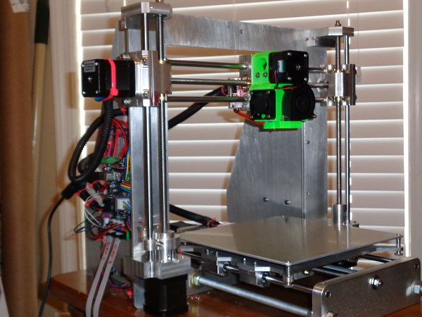
Sitting on my messy desk. Pronterface running to test motion. All axes move, some nicer than others. Z is a bit off, I was never fussy about the two motor system, but it does allow fairly fine adjustment for levelling.
What's left of the original is the frame, smooth and threaded rods, and a couple of motors. I didn't intend to use the frame, it just worked out that way, but as a result, I have a Y range that only allows about half of the print bed to be used. Not a huge deal to move it, but I need to measure how much. I get full coverage in X dimension. I'll also need to see where Z sits once the print head and build platform are installed. So far so good.
MBot3D Printer
MakerBot clone Kit from Amazon
Added heated bed.
Leadscrew self-built printer (in progress)
Duet Wifi, Precision Piezo parts

Anti backlash nut on the Y axis. This seems to be kind of noisy, I'll have to see why.

Same in the head carriage. Smooth as silk, and moves quickly and easily.

Gantry detail with X limit switch. This is on the max side of the X travel, since that's where I put all the wiring. The motor is on that side, as is the Z limit switch, and the Z motors route there, too.

Y motor mount and spaghetti wiring. Nothing even close to resembling a harness yet, but it connects to the RAMPS board, and works.

Sitting on my messy desk. Pronterface running to test motion. All axes move, some nicer than others. Z is a bit off, I was never fussy about the two motor system, but it does allow fairly fine adjustment for levelling.
What's left of the original is the frame, smooth and threaded rods, and a couple of motors. I didn't intend to use the frame, it just worked out that way, but as a result, I have a Y range that only allows about half of the print bed to be used. Not a huge deal to move it, but I need to measure how much. I get full coverage in X dimension. I'll also need to see where Z sits once the print head and build platform are installed. So far so good.
MBot3D Printer
MakerBot clone Kit from Amazon
Added heated bed.
Leadscrew self-built printer (in progress)
Duet Wifi, Precision Piezo parts
|
Re: Beltless I3 project, feedback? March 31, 2018 01:14PM |
Registered: 6 years ago Posts: 3 |
I like what you did with your printer. I am new to the forum and also new to 3dprinters. I attached two pictures of my printer project. The 8mm lead screws are captured by a pair of ball bearings and drive my anti backlash nuts.
|
Re: Beltless I3 project, feedback? April 02, 2018 12:54PM |
Registered: 9 years ago Posts: 465 |
Looks good.
I've been stalled on this for a couple of months, since I've got bigger problems to be solved, and the next thing really is to jet the print head mounted, which seems to require some parts that are currently difficult to get my hands on. I have X, Y and Z motion working well though. It does not go as fast for non-print moves as my belt-driven printer, but I'm planning to use this for filament that will require slower printing, like PETg
MBot3D Printer
MakerBot clone Kit from Amazon
Added heated bed.
Leadscrew self-built printer (in progress)
Duet Wifi, Precision Piezo parts
|
Re: Beltless I3 project, feedback? April 03, 2018 01:18AM |
Registered: 8 years ago Posts: 1,671 |
Check out this video on how the Sherline copes with leadscrew backlash, [www.youtube.com]
looks like something that could be done on 3D printers.
looks like something that could be done on 3D printers.
|
Re: Beltless I3 project, feedback? April 03, 2018 12:16PM |
Registered: 6 years ago Posts: 3 |
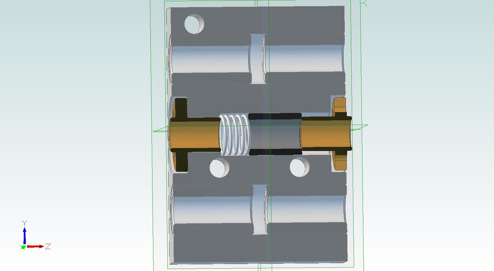
If we want to have round circles and accurate parts from the files it is necessary to control backlash. My way of taking up the backlash is using 2 nuts with a spring between them. The lead screws are also locked in the linear direction using 2 bearings and lock nut.
The attachment is a section through my X axis block.
The attachment is a section through my X axis block.
|
Re: Beltless I3 project, feedback? April 04, 2018 12:59PM |
Registered: 9 years ago Posts: 465 |
Well, I have anti-backlash nuts on both the X and Y axes already, so that at least should be minimal. Probably at least as good as the belts on my other printer, possibly better (I get some ringing on the Y axis of that printer now.)
I figured out what was making noise on the Y axis. The coupler that I'm using for the lead screw isn't correctly centering the lead screw, and it wobbles about .5mm or so, which the nut doesn't like at all. I'll see if I can get a better center, but I've also been considering replacing the couplers altogether with more solid ones.
Also, I want to replace a lot of the PLA parts with something stronger. The other project that I've got on the go is a CNC router. I've been considering making parts from something stronger and more rigid for this printer as well, once the router is complete, I will see what kinds of materials I can make work. In the meantime, I may re-do some of these parts with ABS or PETg.
MBot3D Printer
MakerBot clone Kit from Amazon
Added heated bed.
Leadscrew self-built printer (in progress)
Duet Wifi, Precision Piezo parts
|
Re: Beltless I3 project, feedback? August 10, 2018 04:56PM |
Registered: 6 years ago Posts: 39 |
Hi SupraGuy,
very Interesting your experiment with screws.
I don't like too much belt too, I find it is not enough mechanical.
What is your maximum printing speed ?
The only thing I find difficult with screws it is the alignment between the screw and the guide of the axes, I did bad experiment with my first homemade CNC. The axes were always hard on one side due to tightening due to misalignment.
Alain
|
Re: Beltless I3 project, feedback? August 12, 2018 11:19PM |
Registered: 5 years ago Posts: 6 |
|
Re: Beltless I3 project, feedback? August 13, 2018 11:25AM |
Registered: 9 years ago Posts: 465 |
Well, I just spent the weekend ripping this apart.
Speed looked okay, but as it stood, my print area was restricted to about 180mmX190mm. (Not sure about Z, it was still adequate. Many things that I want to use this for require at least 200mm on at least one axis, so this did not meet design goals. I've been busily printing and otherwise fabricating yet another redesign, some of which are to make use of better parts that I've gotten hold of since the first design was done. The idea is to move to piezo sensors for the Z probe. Mostly I'm trying to reduce mass on the X and Y axes in order to reduce ringing, but my initial testing with the design here is very promising already. (If I were really serious about reducing mass, I'd commit to the Bowden setup, but I'm still going forward with a direct drive extruder for the time being.
Belts will definitely move faster. Using the Arduino/RAMPS board, I could get maybe 80mm/s at 16X stepping. I would probably have gone to 8X (Maybe even 4X) microstepping, which might have perfomed better. (4X microstepping still gives 100steps/mm -- still better resolution than GT2 belts.) Due to other complications (Primarily with hotend mounting) I never actually ran print tests, just motion tests with a weight attached to the carriage to simulate the extruder/hotend, so I don't have print speed tests, but 120mm/s for non-print motion was possible with 2000mm/s^2 acceleration values and not losing steps. (I use 2500mm/s^2 values on my belt printer which still results in mild ringing on the Y axis.)
Alignment is definitely an issue.This is a bigger thing with the Y axis than the X axis, since there are some uncertainties with the mounting of the moving platform on the Y axis. I printed the mounting plate to allow for a little bit of adjustment to where the leadscrew nut bolts on. I've left the option open to include pillow block bearings at each end of the Y axis leadscrew in order to force its alignment. Doing it that way, the leadscrew is fixed parallel to the rails, so wherever the leadscrew mounts to the Y axis platform should remain consistent at any point in its travel.
@G|earsawe: This is true, and is a problem with CNC machines, too. However, I still see significant ringing with the belts on my other printer, as well as for the original design. There's also a limit to the jerk that belts can take without compressing, and there's a limit to how tight you can make them, so completely eliminating slack and imprecision is a matter of diminishing returns from an engineering perspective. I will probably end up reducing my acceleration values further once I start printing, but this printer is NOT intended to be one to make fast prints. My intention is to use this when I want something of higher precision and accuracy. So long as I can obtain reasonable print speed, it will meet my design goals.
Now chances are that I'll never need a resolution of 0.0025mm which I get at 400steps/mm (16X microstepping X 200 full steps/rotation / 8mm per rotation) It seems a little excessive when we're printing a blob of plastic 0.4mm in diameter, but I've never really liked the ~89 steps/mm that the GT2 belts give for resolution. Timing belts for the Z axis should be fine torque-wise, but I hope that you're either gearing down, or carefully selecting your layer heights to work with the available values. The human eye probably can't tell the difference between a square that's 10.0112mm to a side and one that's 10.0000mm to a side, but you can very much see when a set of layers has a variance between 0.19994mm and 0.20227mm. As an example, I often use a layer height of 0.3333333mm as a layer height for model prototypes so that it will print faster than my usual 0.20 or 0.25mm. (Yeah, that's a little over the recommended maximum that my 0.4mm nozzle should print, and layer adhesion is crappy) Even at 400 steps/mm, I can see the "correction" layers every third layer. These pieces often end up in the trash after I've verified fitment/size/placement.
In general, it's an experiment. If it works out well, then that's great. If not, I'll redesign stuff until it works. I've got a lot of options, and a working printer in the meantime.
MBot3D Printer
MakerBot clone Kit from Amazon
Added heated bed.
Leadscrew self-built printer (in progress)
Duet Wifi, Precision Piezo parts
|
Re: Beltless I3 project, feedback? August 15, 2018 02:04AM |
Registered: 6 years ago Posts: 93 |
With a Z resolution of .004mm, you should try .332 for layer height. Your "correction" is likely the motor snapping to the next full step instead of the non-integer microstep you're trying to force.
Cool project. I had an i3 style screwdriven, but it kept tearing up the X v-wheels with an off-center drive. Rods should do better.
I also found the ringing on Y wasn't from the drive or the bearings, but the springs and 3mm bolts anchoring the heat bed. Moving to #8 screws and 15lb. springs from the hardware fixed it. Without the dampening effect of belts, you'll find rigidity problems you never knew you had..I know I did!
Edited 2 time(s). Last edit at 08/15/2018 02:18AM by Diggrr.
|
Re: Beltless I3 project, feedback? August 15, 2018 10:15AM |
Registered: 9 years ago Posts: 465 |
@Diggrr: I'm not actually worried about it. I never did see those problems with the I3 (which used M5 leadscrews at 0.8mm pitch for 4000 steps/mm) and probably I wouldn't really see them with my new printer (using an 8mm lead for 400 steps/mm) except that I did actually look for it.
My current printer doesn't move the print bed for the Y axis, it moves the X gantry. The heated bed moves in the Z axis for this one, so the ringing is definitely the belts. I expect that it's the extra mass of moving the whole gantry, whereas on the X axis, it only moves the carriage. (Which includes the extruder motor) whereas the Y axis, it has to move the carriage, plus the smooth rods, plus the gantry pieces, plus the X axis motor.
Thanks for the warning about rigidity. I'm making some material choices for the frame, and if I want to use printed parts for some of it. I think you've just convinced me to use the heavier but stronger materials.
MBot3D Printer
MakerBot clone Kit from Amazon
Added heated bed.
Leadscrew self-built printer (in progress)
Duet Wifi, Precision Piezo parts
|
Re: Beltless I3 project, feedback? August 15, 2018 11:26AM |
Registered: 9 years ago Posts: 465 |
This is the progress so far on the second generation. I've changed out the "springy" leadscrew couplers for solid ones. The rods are now in a horizontal alignment, instead of vertical like before. The leadscrew isn't in the center of the rods anymore, since that would get int he way of the hot end. Overall, mounting the extruder and hotend was so much simpler that way. (I did design a holder for the hot end to use a Bowden extruder (Which both hot end and extruder were originally supposed to be) so I could change to that if I decide that I don't like the direct drive, but I doubt that it will come to that. The one piece that holds the anti-backlash nut needs a bit of a change, I want to move it a little closer to the right, so I don't have to buy a longer leadscrew.  This piece broke when I dropped the carriage assembly, and is glued back together. Pretty sure that the epoxy is stronger than the layered ABS anyway.
I still have some cable management things to sort out, but I'm pretty happy with the X endstop mounting solution.
MBot3D Printer
MakerBot clone Kit from Amazon
Added heated bed.
Leadscrew self-built printer (in progress)
Duet Wifi, Precision Piezo parts
This piece broke when I dropped the carriage assembly, and is glued back together. Pretty sure that the epoxy is stronger than the layered ABS anyway.
I still have some cable management things to sort out, but I'm pretty happy with the X endstop mounting solution.
MBot3D Printer
MakerBot clone Kit from Amazon
Added heated bed.
Leadscrew self-built printer (in progress)
Duet Wifi, Precision Piezo parts
|
Re: Beltless I3 project, feedback? August 15, 2018 10:18PM |
Registered: 7 years ago Posts: 507 |
Out of curiosity, why not set it up with a z axis bed? If you take a prusa and rotate it by 90 degrees about the x axis, and again rotate the bed by 90 degrees about the x axis, that's basically what you'd get. You'd just need to build up the frame in certain areas. Ordinarily you'd end up with a funky drive system with y axis leadscrews and a belt driven Z axis, but since yours is entirely leadscrew driven it won't have that odd mismatch.
|
Re: Beltless I3 project, feedback? August 16, 2018 10:14AM |
Registered: 9 years ago Posts: 465 |
|I had actually considered that as a setup, with 2 Y axis motors. Who knows, there may yet be a third generation of this thing.
My primary reason for sticking with the bed moving in the Y axis is around the matter of moving mass. I do realize that throwing the print back and forth on the Y axis is asking for certain problems, but even a large print probably won't have the mass that the X carriage, rods and motor are going to have. I strongly suspect this to be the reason why my MBot printer rings in the Y axis, even after lowering my Y acceleration.
I think that I will be building a third printer. Looking at my parts bin, I certainly have the hardware, but I think that this one is probably going to end up as a Bowden fed CoreXY, and may end up with a Volcano hot end with a larger nozzle for faster building. I think that the CNC router table is probably my next DIY project though.
MBot3D Printer
MakerBot clone Kit from Amazon
Added heated bed.
Leadscrew self-built printer (in progress)
Duet Wifi, Precision Piezo parts
|
Re: Beltless I3 project, feedback? August 17, 2018 12:01AM |
Registered: 7 years ago Posts: 507 |
It's not always all to do with the mass of the moving parts necessarily. Another issue is to do with the print itself moving. Shaking the print around can cause it to oscillate like a tuning fork, this is worse with taller or skinnier prints as the print will wobble on the bed and give ringing artifacts even if the bed itself is rock solid and doesn't wobble.
I suggest you do a CNC router next, personally I like using them more, they tend to produce cleaner looking parts and I like the look and feel of metals and woods more than I do plastic. That and we need more hobby cnc users in the community.
I suggest you do a CNC router next, personally I like using them more, they tend to produce cleaner looking parts and I like the look and feel of metals and woods more than I do plastic. That and we need more hobby cnc users in the community.
|
Re: Beltless I3 project, feedback? August 20, 2018 05:52PM |
Registered: 9 years ago Posts: 465 |
Not as much progress as I'd have liked this weekend.
My other printer seems to have decided that it can't print a solid layer on top of a partial infill layer. I'm blaming the part cooling fan and the generally cooler weather that we've been having lately here. It seems to be overcooling and the solid layer starts curling up immediately as it's being laid down. I'll have to turn that off in the slic3r settings and re-do a bunch of parts.
In the meantime, I set up the parts of the Z tower for laser cutting in 4.5mm polycarbonate. I have some limited access to a very nice laser, but chances are that I won't get real access to it until this coming Friday. Some of the parts I've got printed, but I could re-do on the laser, and that would be stronger than printed plastic for sure. I'll probably also use some printed supports/braces to complete them, but I've got most of the week to get those made.
Yes, a CNC router is most certainly in the works. I've been collecting parts and plans for a while. This is almost certainly going to be a 2 stage build, with a "bootstrap" build to make improved parts. Most notably, my ability to make a torsion box for the bed is poor, but what I can build should be adequate to make the parts for one. I believe that I can do an adequate job on the gantry, though I may rebuild that, too, since the CNC should have the ability to make for a lighter weight gantry that is at least as stiff as one that I can make with the carpentry tools at my disposal.
In the meantime, I want to get this beast up and running.
Originally, this was going to look a lot like the I3 that I started out with, but it's looking more and more like I'm going to put it in a box. I keep questioning the rigidity of the bed support. Building the frame as a part of a box should produce a nice rigid frame.
MBot3D Printer
MakerBot clone Kit from Amazon
Added heated bed.
Leadscrew self-built printer (in progress)
Duet Wifi, Precision Piezo parts
|
Re: Beltless I3 project, feedback? August 29, 2018 11:23AM |
Registered: 9 years ago Posts: 465 |
Version 2 almost complete.
A quick virtual assembly of the various pieces.
Designed in TinkerCAD, since it's a nice on-line tool and I can work from wherever I have a web browser. and it was perfectly adequate to the job.
I started assembly of the laser cut acrylic parts last night.
Since I already had the artwork for another fan grille, I decided to use the Imperial Cog for the center of the fan grille which will go over the Duet.
Overall, I'm quite pleased with the results. I initially mismeasured my motors, and thought for some reason that they were 45mm long, (I swear I measured 3 times!) and for whatever reason, I decided that the top of the motor platforms for the Z axis should be 50mm. (Less 4.5mm for material thickness leaves 45.5mm clearance. Should be good right? Well, until I tried to fit the motors, and they're 48mm. So the base plate has openings in them to allow for the motors to protrude a little below the towers. I had initially made the same mistake for the X motor, and I had to revise my drawings to allow for it. I suppose I could have revised my Z towers at the same time, but I kind of like having the openings under there, since it makes motor installation and removal possible without disassembling the whole printer.
Although it has a large footprint, I'm much happier with the overall design than I was with it using much of the old I3 frame... Of course now I have the old I3 frame hanging around and almost all of the original parts, save a few smooth rods, power supply and motors.
Next project is a CNC router, but I forsee after that building a CoreXY (Probably as an inital project for the CNC router.)
MBot3D Printer
MakerBot clone Kit from Amazon
Added heated bed.
Leadscrew self-built printer (in progress)
Duet Wifi, Precision Piezo parts
A quick virtual assembly of the various pieces.

Designed in TinkerCAD, since it's a nice on-line tool and I can work from wherever I have a web browser. and it was perfectly adequate to the job.
I started assembly of the laser cut acrylic parts last night.

Since I already had the artwork for another fan grille, I decided to use the Imperial Cog for the center of the fan grille which will go over the Duet.

Overall, I'm quite pleased with the results. I initially mismeasured my motors, and thought for some reason that they were 45mm long, (I swear I measured 3 times!) and for whatever reason, I decided that the top of the motor platforms for the Z axis should be 50mm. (Less 4.5mm for material thickness leaves 45.5mm clearance. Should be good right? Well, until I tried to fit the motors, and they're 48mm. So the base plate has openings in them to allow for the motors to protrude a little below the towers. I had initially made the same mistake for the X motor, and I had to revise my drawings to allow for it. I suppose I could have revised my Z towers at the same time, but I kind of like having the openings under there, since it makes motor installation and removal possible without disassembling the whole printer.
Although it has a large footprint, I'm much happier with the overall design than I was with it using much of the old I3 frame... Of course now I have the old I3 frame hanging around and almost all of the original parts, save a few smooth rods, power supply and motors.
Next project is a CNC router, but I forsee after that building a CoreXY (Probably as an inital project for the CNC router.)
MBot3D Printer
MakerBot clone Kit from Amazon
Added heated bed.
Leadscrew self-built printer (in progress)
Duet Wifi, Precision Piezo parts
|
Re: Beltless I3 project, feedback? August 31, 2018 11:20AM |
Registered: 9 years ago Posts: 465 |
Well, we'll call last night a hard fail.
Most of the mechanical build is done, but I guess my gantry pieces were a bit weak. Also, at minimum Z distance, the gantry pieces hit the motor mounts with the nozzle about 2mm from the bed. I raised the bed by 4.5mm with some shims, and discovered that the rod couplers that I had also interfered with the gantry. That was what resulted in the broken tab as pictured above.
So I need to redesign the gantry pieces. I'm going to raise the bearings a little, and make the mount for the lead screws more robust.
Two steps forward, one step back.
MBot3D Printer
MakerBot clone Kit from Amazon
Added heated bed.
Leadscrew self-built printer (in progress)
Duet Wifi, Precision Piezo parts
|
Re: Beltless I3 project, feedback? September 04, 2018 01:38PM |
Registered: 9 years ago Posts: 465 |
Well, the wiring is much neater now. After blowing up the power supply, I decided to do what I could, and ran the wiring for the carriage and the Z axis into some split-loom. I was going to use drag chain, but it seems overkill right now. Maybe I'll change my mind about htat later, but for now, the split-loom seems to be adequate.
Most of what goes to the Duet Wifi runs inside the space inside the Z towers now, which is kind of a nice touch. I added a couple of LED strips to the top for lighting when the printer is powered on.
Wiring to the Duet Wifi:
An overview of the printer in its current state. The power supply has been removed, and I still need to do something with the Y axis wiring, as it's still a bit of a mess. I'd still like to have used the drag chain here, but I am short on the space needed under the Y carriage by about 3mm for what I'd need to allow the drag chain to work.
you can see in the photo the score mark from when I missed the calibration on the piezo sensors, and it dragged the hot end over the aluminum bed to the corner I'm having some difficulty in adjusting the sensors, they seem to either want to trigger almost at random when the printer is moving, or else they just don't. I'm thinking that I might want to increase the probe speed a little to get a more sure fire on the sensors.
The gantry pieces are held in place with a nut that is spring-loaded into the pieces so that if it crashes into the bed, the spring will allow the nut to come out the bottom of the printed piece. Call that a lesson from the broken gantry pieces earlier, but it also allows the hot end to be spring-loaded against the heat bed and then dragged. I am starting to regret my choice of going to under-bed sensors, and thinking that maybe a switch-type probe on the hot end would be more desireable, in that it at least would have few false positives.
Most of what goes to the Duet Wifi runs inside the space inside the Z towers now, which is kind of a nice touch. I added a couple of LED strips to the top for lighting when the printer is powered on.
Wiring to the Duet Wifi:


An overview of the printer in its current state. The power supply has been removed, and I still need to do something with the Y axis wiring, as it's still a bit of a mess. I'd still like to have used the drag chain here, but I am short on the space needed under the Y carriage by about 3mm for what I'd need to allow the drag chain to work.

you can see in the photo the score mark from when I missed the calibration on the piezo sensors, and it dragged the hot end over the aluminum bed to the corner
I'm having some difficulty in adjusting the sensors, they seem to either want to trigger almost at random when the printer is moving, or else they just don't. I'm thinking that I might want to increase the probe speed a little to get a more sure fire on the sensors.The gantry pieces are held in place with a nut that is spring-loaded into the pieces so that if it crashes into the bed, the spring will allow the nut to come out the bottom of the printed piece. Call that a lesson from the broken gantry pieces earlier, but it also allows the hot end to be spring-loaded against the heat bed and then dragged. I am starting to regret my choice of going to under-bed sensors, and thinking that maybe a switch-type probe on the hot end would be more desireable, in that it at least would have few false positives.
|
Re: Beltless I3 project, feedback? September 04, 2018 03:44PM |
Registered: 7 years ago Posts: 619 |
Did you do this all in TinkerCAD? I use this all the time for fast projects, but never for something this elaborate!
Nice work.
DLC
Kits: Folgertech Kossel 2020 upgraded E3Dv6, Anet A8 upgraded E3Dv6, Tevo Tarantula enhanced parts and dual-head, TronXY X5SA Pro(E3DHemera).
Scratch: Large bed Cartesian, exchangeable heads, Linear slide Delta, Maker-Beam XL Micro Delta, 220x220CoreXY.
Nice work.
DLC
Kits: Folgertech Kossel 2020 upgraded E3Dv6, Anet A8 upgraded E3Dv6, Tevo Tarantula enhanced parts and dual-head, TronXY X5SA Pro(E3DHemera).
Scratch: Large bed Cartesian, exchangeable heads, Linear slide Delta, Maker-Beam XL Micro Delta, 220x220CoreXY.
|
Re: Beltless I3 project, feedback? September 04, 2018 04:16PM |
Registered: 9 years ago Posts: 465 |
yeah, I actually can work pretty fast in TinkerCAD, though the last couple of updates make it kind of sloggy on my aging laptop. I do have some better CAD software, but I kind of got most of it done with this, since I never really expected to do quite this much.Quote
dlc60
Did you do this all in TinkerCAD? I use this all the time for fast projects, but never for something this elaborate!
Nice work.
DLC
The original intent was that the Piezo sensor blocks, gantry and the leadscrew drive for the Y axis would be 3D printed, and TinkerCAD was just fine for that, the rest I was going to do on my tablesaw, for which I just needed some base measurements. Then I did up a base plate, and when I ran the idea past a friend who has a laser cutter and a bunch of 4.5mm acryllic, I ended up doing this kind of quickly.
Since all of the individual pieces were there in TinkerCAD, it wasn't too hard to take the various bits and place them in 3D relative to each other. I just had to squish/extrude the pieces that I did in 2D to the material 4.5mm thickness.
It wasn't the best of design software choices, I'll grant, but it was mostly done on my laptop which I don't have my "good" CAD software loaded on.

Sorry, only registered users may post in this forum.