Home
>
Reprappers
>
Topic
Will this kind of design work?
Posted by kranlor12
|
Will this kind of design work? March 09, 2021 12:21PM |
Registered: 3 years ago Posts: 5 |
Hello everyone!
It is pretty awesome to be part of this community, and since it is my first post I want to thank anyone in advance for the help provided.
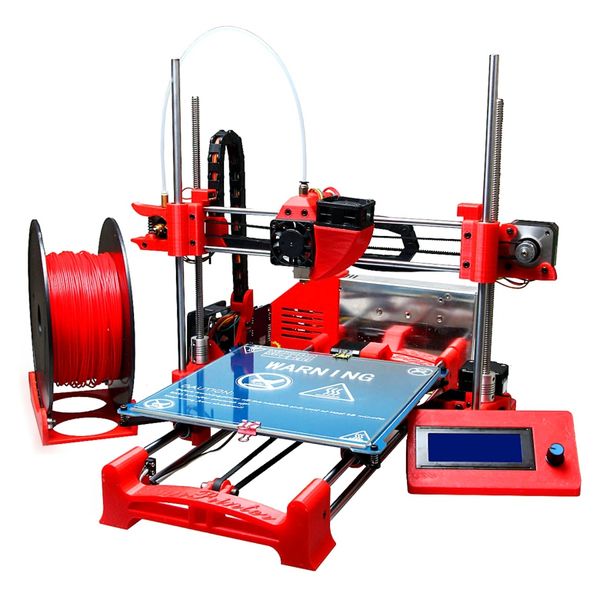
I'm currently trying to build my first 3D printer from scratch, I want it to have a lot of printed parts in order to reduce some costs (I have access to 3 more printers) and found an interesting design where I'm basing all my drawings (Kunprinter K86, see first attachment). I can identify some flaws on that one like belt tensioners and not having a support on top of Z-Axis. My question really is, will this kind of printer be good speaking of quality of print and structure stability in general, to invest time and money upon, or should I just go with a aluminum extrusion one? (thinking of prusa i3 2020).
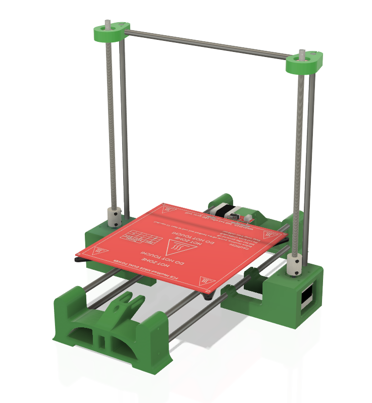
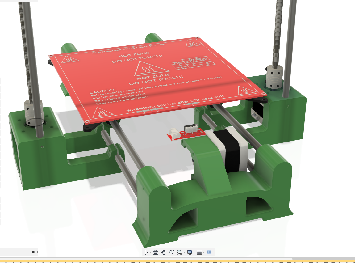
I also attached some pictures of the progress I've made with the design without the X-Axis, but I'm asking this to see if it is worth finishing the project and try to put it all together, or I should go with the extrusion frame option.
Thank you everyone that can contribute to this post!
It is pretty awesome to be part of this community, and since it is my first post I want to thank anyone in advance for the help provided.
I'm currently trying to build my first 3D printer from scratch, I want it to have a lot of printed parts in order to reduce some costs (I have access to 3 more printers) and found an interesting design where I'm basing all my drawings (Kunprinter K86, see first attachment). I can identify some flaws on that one like belt tensioners and not having a support on top of Z-Axis. My question really is, will this kind of printer be good speaking of quality of print and structure stability in general, to invest time and money upon, or should I just go with a aluminum extrusion one? (thinking of prusa i3 2020).
I also attached some pictures of the progress I've made with the design without the X-Axis, but I'm asking this to see if it is worth finishing the project and try to put it all together, or I should go with the extrusion frame option.
Thank you everyone that can contribute to this post!
|
Re: Will this kind of design work? March 09, 2021 03:33PM |
Registered: 3 years ago Posts: 26 |
It might 'work', but it is unlikely to work well.
Frame rigidity is important so that, for example, the forces applied by the y motor reach only the bed rather than being shared by the bed and frame deformation and so that vibrations do not spoil the accuracy of hotend and bed location. Having no elements to prevent side to side deformation of the frame will allow the left to right movement of the extruder to cause frame movement.
If you do go with this design then you should consider grinding flats or holes into the rods to locate setscrews so that the forces of belt tension are not held by friction alone. I have had linear rods slide through the plastic when the force of a locating screw was insufficient to resist the belt tension.
I also see that the y belt is not parallel to the bed rails and so there might be some 'cosine error' in bed movement.
Having a bearing to locate the tops of the lead screws might seem like a good idea, but if the screws are not exactly straight, and most are not, then having the top and bottom restrained guarantees z-wobble-related artefacts.
The part fan arrangement is likely not to work because axial fans do not produce enough pressure to feed much air though a funnel. Consider using a blower-style fan instead.
If you want a printer for printing then I suggest that you consider the surprisingly good for the price Chinese printers, or the better but more expensive offerings from, for example, Prusa. If you want a self-built printer then you probably should look at the various designs discussed elsewhere on this forum.
Good luck!
Edited 1 time(s). Last edit at 03/09/2021 03:36PM by MJLew.
|
Re: Will this kind of design work? March 09, 2021 08:25PM |
Registered: 3 years ago Posts: 93 |
I have a Portabee printer that uses a similar-looking design. I don't know how it compares to modern printers, but the Portabee sold more than one thousand units and a lot of people, including me, liked it. I'm currently fixing up my Portabee and printing out some replacement parts.
In the Portabee, the 2 Z-axis motors and the 1 Y-axis motor all lie in a straight line. This apparently provides enough stability, while still allowing the printer to be compactly disassembled and packed for transportation in a laptop bag.
[reprap.org]
Your design seems to place the 3 base motors in a triangular configuration, which may be better for stability since the weight is distributed across a wider area. There is a mod for the Portabee that adds some extra bracing legs to improve stability:
[reprap.org]
I've been recently updating the Portabee wiki page at [reprap.org], so you can find some more information about it (including full build instructions and downloadable 3D models for the parts) there.
Thanks for posting about your printer design. I had been wondering how to modify my Portabee, which uses a direct-drive extruder, to convert it to a Bowden-tube setup. Because of the similarity between your design and the Portabee design, it looks like the extruder and Bowden-tube mechanics in your design can easily be applied to the Portabee also.
Edited 2 time(s). Last edit at 03/09/2021 08:49PM by qrp-gaijin.
In the Portabee, the 2 Z-axis motors and the 1 Y-axis motor all lie in a straight line. This apparently provides enough stability, while still allowing the printer to be compactly disassembled and packed for transportation in a laptop bag.
[reprap.org]
Quote
Want to share my Portabee. Its quite stable, I think because the 3 motors under the base which are heavy enough to hold the printer steady.
Your design seems to place the 3 base motors in a triangular configuration, which may be better for stability since the weight is distributed across a wider area. There is a mod for the Portabee that adds some extra bracing legs to improve stability:
[reprap.org]
Quote
one of the design compromises we made in order to make the Portabee easily flat-packable (to an extent) and do so repeatably with as little hassle as possible was that the entire Y axis had to sit on the base rods, and as a result the stability is fully dependent on the stiffness of those rods. We opted for M6 for the base rods just so that there will be only one threaded rod requirement for the printer (z 'leadscrews' are M6 as well). With larger diameter rods the stability will improve.
Stability wise during use, we find that it is not a big problem unless the printer gets bumped or knocked over. Maybe much like a vase sitting there doing just fine until something bad happens (baseball, jumping cat, nunchuck etc). The base is heavier than the x axis (3 motors on the base vs 2 on the x axis) but yes, more stability is always a good thing.
We have tested a 'Y-brace' mod and it works pretty well. Basically this mod allows two printed removable braces to be attached to the (modified) y bearing holders, supporting them directly. The printer can still be taken apart fairly easily for packing if this is not made permanent - there is an option to permanently bolt the braces if the printer is not intended to be moved around, at least in its 'flat-packed' form.
I've been recently updating the Portabee wiki page at [reprap.org], so you can find some more information about it (including full build instructions and downloadable 3D models for the parts) there.
Thanks for posting about your printer design. I had been wondering how to modify my Portabee, which uses a direct-drive extruder, to convert it to a Bowden-tube setup. Because of the similarity between your design and the Portabee design, it looks like the extruder and Bowden-tube mechanics in your design can easily be applied to the Portabee also.
Edited 2 time(s). Last edit at 03/09/2021 08:49PM by qrp-gaijin.
|
Re: Will this kind of design work? March 09, 2021 11:46PM |
Registered: 6 years ago Posts: 1,007 |
|
Re: Will this kind of design work? March 10, 2021 03:27AM |
Registered: 9 years ago Posts: 483 |

|
Re: Will this kind of design work? March 10, 2021 03:28PM |
Registered: 3 years ago Posts: 26 |
|
Re: Will this kind of design work? March 10, 2021 03:45PM |
Registered: 3 years ago Posts: 5 |
Quote
MJLew
It might 'work', but it is unlikely to work well.
Frame rigidity is important so that, for example, the forces applied by the y motor reach only the bed rather than being shared by the bed and frame deformation and so that vibrations do not spoil the accuracy of hotend and bed location. Having no elements to prevent side to side deformation of the frame will allow the left to right movement of the extruder to cause frame movement.
If you do go with this design then you should consider grinding flats or holes into the rods to locate setscrews so that the forces of belt tension are not held by friction alone. I have had linear rods slide through the plastic when the force of a locating screw was insufficient to resist the belt tension.
I also see that the y belt is not parallel to the bed rails and so there might be some 'cosine error' in bed movement.
Having a bearing to locate the tops of the lead screws might seem like a good idea, but if the screws are not exactly straight, and most are not, then having the top and bottom restrained guarantees z-wobble-related artefacts.
The part fan arrangement is likely not to work because axial fans do not produce enough pressure to feed much air though a funnel. Consider using a blower-style fan instead.
If you want a printer for printing then I suggest that you consider the surprisingly good for the price Chinese printers, or the better but more expensive offerings from, for example, Prusa. If you want a self-built printer then you probably should look at the various designs discussed elsewhere on this forum.
Good luck!
This is the kind of response I was looking for, totally accurate for what the design seems to offer. Although I really like this kind of printer for it's looks and simplicity, I'll try and put an aluminum extrusion one instead as I found a supplier in my country. Sometimes I use the printers on the lab for really accurate dimensions prints but I'd like my own printer to do that kind of stuff too, thinking ahead of the calibration process seems like a nightmare with this one so I slept it over and decided to go the safe way. Thanks again for taking the time to discuss this.
|
Re: Will this kind of design work? March 10, 2021 03:50PM |
Registered: 3 years ago Posts: 5 |
Quote
qrp-gaijin
I have a Portabee printer that uses a similar-looking design. I don't know how it compares to modern printers, but the Portabee sold more than one thousand units and a lot of people, including me, liked it. I'm currently fixing up my Portabee and printing out some replacement parts.
In the Portabee, the 2 Z-axis motors and the 1 Y-axis motor all lie in a straight line. This apparently provides enough stability, while still allowing the printer to be compactly disassembled and packed for transportation in a laptop bag.
[reprap.org]
Quote
Want to share my Portabee. Its quite stable, I think because the 3 motors under the base which are heavy enough to hold the printer steady.
Your design seems to place the 3 base motors in a triangular configuration, which may be better for stability since the weight is distributed across a wider area. There is a mod for the Portabee that adds some extra bracing legs to improve stability:
[reprap.org]
Quote
one of the design compromises we made in order to make the Portabee easily flat-packable (to an extent) and do so repeatably with as little hassle as possible was that the entire Y axis had to sit on the base rods, and as a result the stability is fully dependent on the stiffness of those rods. We opted for M6 for the base rods just so that there will be only one threaded rod requirement for the printer (z 'leadscrews' are M6 as well). With larger diameter rods the stability will improve.
Stability wise during use, we find that it is not a big problem unless the printer gets bumped or knocked over. Maybe much like a vase sitting there doing just fine until something bad happens (baseball, jumping cat, nunchuck etc). The base is heavier than the x axis (3 motors on the base vs 2 on the x axis) but yes, more stability is always a good thing.
We have tested a 'Y-brace' mod and it works pretty well. Basically this mod allows two printed removable braces to be attached to the (modified) y bearing holders, supporting them directly. The printer can still be taken apart fairly easily for packing if this is not made permanent - there is an option to permanently bolt the braces if the printer is not intended to be moved around, at least in its 'flat-packed' form.
I've been recently updating the Portabee wiki page at [reprap.org], so you can find some more information about it (including full build instructions and downloadable 3D models for the parts) there.
Thanks for posting about your printer design. I had been wondering how to modify my Portabee, which uses a direct-drive extruder, to convert it to a Bowden-tube setup. Because of the similarity between your design and the Portabee design, it looks like the extruder and Bowden-tube mechanics in your design can easily be applied to the Portabee also.
Hey! I didn't know the Portabee before you posted this, what an amazing design, so simple but seems really useful. Unfortunately, I'm looking for a 20x20x20 printer and I'm not sure that will work with longer axis. I'll save the Wiki for a future reference project, as this seems to be awesome to put together, maybe make a workshop about it as a DIY cheap printer when I do it.

I want to see the quality of this printer, maybe you can share few pictures of this?
Thanks for taking the time to put together and update the Wiki page, your contribution to the community is amazing.
|
Re: Will this kind of design work? March 11, 2021 09:20AM |
Registered: 3 years ago Posts: 55 |
Ah, it does not look stable to me. Bed would be fine on flat surface, the X-axis looks susceptible to vibration.
If it isn't your first printer, I'd be thinking more like core-xy or maybe even delta robot.
core-xy is likely a more traveled road and to my mind looks better for those printers where you want an enclosure.
But if you want moving y-bed printer, then here is one I'd recently done from scratch .. it is my first printer. It is updated iTopie.
[iTopie400+](https://github.com/kpishere/RepRap-iTopie)
But if your wanting to improve your design, I'm thinking needs more triangles and/or bigger ones in the corners genrally. Also, 8mm rods not very stiff, squares or angles or T's are stiffer.
|
Re: Will this kind of design work? March 11, 2021 09:30AM |
Registered: 3 years ago Posts: 93 |
Yes, it would be great to hear of your experience if you try building a Portabee or similar style printer. For now, I'm still tuning my printer parameters to get the best quality (hole size tuning is rather time consuming), while printing out replacement Portabee parts. Eventually I should have enough replacement parts to build a second, possibly modified, Portabee. Actually, I ordered my Portabee pre-assembled, so I never had the joy (?) of assembling it completely from scratch.Quote
kranlor12
I didn't know the Portabee before you posted this, what an amazing design, so simple but seems really useful. Unfortunately, I'm looking for a 20x20x20 printer and I'm not sure that will work with longer axis. I'll save the Wiki for a future reference project, as this seems to be awesome to put together, maybe make a workshop about it as a DIY cheap printer when I do it.
Because I'm not yet experienced with 3D printing and have not yet completed extensive calibration and testing of my printer, I fear that any prints of mine that I could show will not be representative of the maximum Portabee print quality. Instead, let me point you to some others' images and videos.Quote
kranlor12
I want to see the quality of this printer, maybe you can share few pictures of this?
A video with some typical prints from the Portabee. Nice comparison at the end of the video of uncalibrated and calibrated print results.
[www.youtube.com]
The written comments on the YouTube video page specify that the best layer height seems to be 0.3 mm. Hm, maybe more information to add to the Portabee wiki... The author also stated: "For my small-part (as shown in the video), I was able to get the outer dimensions to +/- .005", which is pretty awesome. But I highly doubt I could do that with a full-printbed part."
Some other images:
[venturebeat.com]

[blog.tldnr.org]


[www.cygig.com]


What do you think of the print quality? It looks reasonable to me given the machine specs, but I don't know about how it compares to modern 3D printers with similar specs.
Also, I wonder if there are any other well-proven RepRap designs similar to the Portabee that are also small and portable enough be fit inside a laptop bag. Are there any? I guess that making a small printer with many 3D printed parts is no longer the modern and reliable way, but still I think it's an interesting design challenge -- one that Portabee successfully solved -- to make a RepRap that is both portable and highly self-replicating (i.e. using many 3D printed parts).
|
Re: Will this kind of design work? March 11, 2021 12:39PM |
Registered: 3 years ago Posts: 55 |
@grp-gaijin Your parts look pretty good. There does seem to be an under/over extrusion issue that is causing roughness. A little hard to tell from the pictures due to resolution but I'd hazard it is over-extrusion. Have you calibrated your extruder? Would look at that if you have not done so.
|
Re: Will this kind of design work? March 11, 2021 06:27PM |
Registered: 3 years ago Posts: 93 |
Thanks for the feedback on the quality of the Portabee prints. Those prints are made with the Portabee printer, but they were not made by me -- the pictures are from other people who used the Portabee printer.Quote
NovaHuta
@grp-gaijin Your parts look pretty good. There does seem to be an under/over extrusion issue that is causing roughness. A little hard to tell from the pictures due to resolution but I'd hazard it is over-extrusion. Have you calibrated your extruder?
As for my Portabee printer, no, I still need to calibrate the extruder. I'm reworking the mechanics of my entire extruder (replacing the original extruder block and printed gears with new self-printed replacement parts), and once I am satisfied with the fit of the new extruder parts, I hope to calibrate the extruder. I'm still a little afraid to be messing around with firmware settings, since the Marlin firmware on my board seems to be some custom version that was modified specifically for the Portabee, and if I mess up the firmware or the firmware settings, I'm not sure I would be able to restore the firmware to its original condition.
For example, [marlinfw.org] says that M503 should "Print a concise report of all current settings (in SRAM) to the host console", which should include the current steps-per-E setting, but on my board the M503 command does nothing. So something is odd about my firmware. Therefore, I have no way of knowing how many steps-per-E are currently configured, which makes calibration of the extruder a little tricky. On the other hand, I read about another Portabee user who simply calibrated the extruder in hardware, by adjusting the idler block tension to ensure that when the software sends the command to extrude 5 mm of filament, then the idler block tension is set just right so that the extruder advances the filament by exactly 5 mm.
[blog.tldnr.org]
Quote
I have set the amount to 5mm and set a couple of marks on the filament with a distance of 5mm. Then I slowed down the speed to about 50mm. I hitted the Extrude button in pronterface and checked how far the mark has moved. Then I adjusted the spring compression in a way that exactly 5mm are extruded. I took me only two attempts. On my Portabee the springs are quite tight with only a small amount of compression remaining.

Maybe I'm paranoid, but I would feel nervous about using a marker to make measuring marks on my filament like that. The ink from the marker will get sent through the hot end and might leave some residue on the inside of the hot end that could lead to a later clog. Or maybe I'm worrying too much?
|
Re: Will this kind of design work? March 11, 2021 06:35PM |
Registered: 3 years ago Posts: 5 |
Quote
qrp-gaijin
Thanks for the feedback on the quality of the Portabee prints. Those prints are made with the Portabee printer, but they were not made by me -- the pictures are from other people who used the Portabee printer.Quote
NovaHuta
@grp-gaijin Your parts look pretty good. There does seem to be an under/over extrusion issue that is causing roughness. A little hard to tell from the pictures due to resolution but I'd hazard it is over-extrusion. Have you calibrated your extruder?
As for my Portabee printer, no, I still need to calibrate the extruder. I'm reworking the mechanics of my entire extruder (replacing the original extruder block and printed gears with new self-printed replacement parts), and once I am satisfied with the fit of the new extruder parts, I hope to calibrate the extruder. I'm still a little afraid to be messing around with firmware settings, since the Marlin firmware on my board seems to be some custom version that was modified specifically for the Portabee, and if I mess up the firmware or the firmware settings, I'm not sure I would be able to restore the firmware to its original condition.
For example, [marlinfw.org] says that M503 should "Print a concise report of all current settings (in SRAM) to the host console", which should include the current steps-per-E setting, but on my board the M503 command does nothing. So something is odd about my firmware. Therefore, I have no way of knowing how many steps-per-E are currently configured, which makes calibration of the extruder a little tricky. On the other hand, I read about another Portabee user who simply calibrated the extruder in hardware, by adjusting the idler block tension to ensure that when the software sends the command to extrude 5 mm of filament, then the idler block tension is set just right so that the extruder advances the filament by exactly 5 mm.
[blog.tldnr.org]
Quote
I have set the amount to 5mm and set a couple of marks on the filament with a distance of 5mm. Then I slowed down the speed to about 50mm. I hitted the Extrude button in pronterface and checked how far the mark has moved. Then I adjusted the spring compression in a way that exactly 5mm are extruded. I took me only two attempts. On my Portabee the springs are quite tight with only a small amount of compression remaining.
Maybe I'm paranoid, but I would feel nervous about using a marker to make measuring marks on my filament like that. The ink from the marker will get sent through the hot end and might leave some residue on the inside of the hot end that could lead to a later clog. Or maybe I'm worrying too much?
If it's a Portabee kit it could be a custom firmware refined to work with the printer, if you don't have a lot of experience with firmware you could do some research I bet you can find the exact vanilla setting for it so you have a backup in case you mess anything.
Answering the marker on the filament to calibrate, it won't do any harm to the hot end, I have done this many times and its the standard way of calibrating it so lots of people have done it without any harm to their hardware.
You got me really interesting in the Portabee, do you think it could be modified for a 20x20 bed? In terms of stability...
|
Re: Will this kind of design work? March 12, 2021 11:23AM |
Registered: 3 years ago Posts: 93 |
My guess is that you would need to make some changes in the design to improve the stability (a wider base, and a less-massive extruder using a Bowden-tube setup?) while sacrificing portability, and the changed design might then end up looking like the printer that you posted at the beginning of this thread.Quote
kranlor12
You got me really interesting in the Portabee, do you think it could be modified for a 20x20 bed? In terms of stability...

Also, this gentleman basically rebuilt the Portabee with his own custom frame components, so maybe it can give you some ideas.
[www.igorkromin.net]
[www.igorkromin.net]
[www.igorkromin.net]
[www.igorkromin.net]
[www.igorkromin.net]
If I've understood correctly, the gentleman referenced above (in the part-3 link) made the Y-axis rods longer, thus (potentially) increasing the print area:
Quote
The only changes to the y-axis were to use longer steel rods. I simply got 300mm rods in place of the original Portabee rods.
However, it seems he still used the original print bed from Portabee, which would mean that although the Y-axis could move more, his print bed wasn't physically large enough to take advantage of the extra motion.
Edited 1 time(s). Last edit at 03/12/2021 11:26AM by qrp-gaijin.
|
Re: Will this kind of design work? September 26, 2021 01:11AM |
Registered: 3 years ago Posts: 93 |
Quote
kranlor12
I'm currently trying to build my first 3D printer from scratch, I want it to have a lot of printed parts in order to reduce some costs (I have access to 3 more printers) and found an interesting design where I'm basing all my drawings (Kunprinter K86, see first attachment).
Just wondering, is there any update on this project?
Quote
MJLew
It might 'work', but it is unlikely to work well.
Frame rigidity is important
Having spent the past several months getting to know my Portabee (a similar design) in detail, I have finally started to climb the learning curve (that countless others before me have ascended) and agree that this sort of design has its limitations. But it's good enough for my non-demanding printing purposes, and it's good enough to print replacement parts for itself so that the printer can keep going indefinitely.
I plan to keep my RepRap going as long as possible, but it's somehow a little bit disheartening that nobody anymore seems to spend time building old-school, plastic-parts, minimum-vitamin RepRaps. I guess it doesn't make sense anymore in terms of time/money investment vs. quality of the final prints, but for me there's a certain kind of minimalist satisfaction (a "back-to-basics" kind of feeling) in having a machine that doesn't require exotic, custom-machined parts (vitmains).
Sorry, only registered users may post in this forum.