Prusa i3 build log: Upgrade original Mendel
Posted by Loska
|
Prusa i3 build log: Upgrade original Mendel January 23, 2016 02:34AM |
Registered: 8 years ago Posts: 27 |
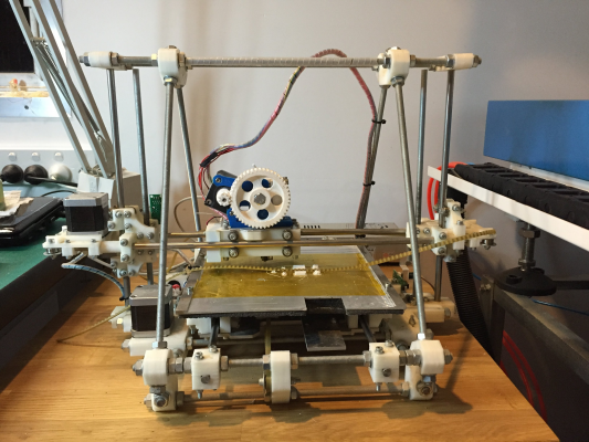
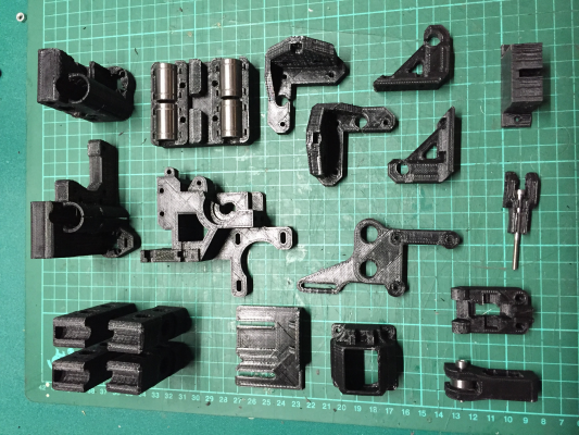
My old faithful Mendel, built in 2008 and regularly used has been getting a bit out of date although still going strong. Remarkably, the plastics, printed by Nophead, have survived the distance with only minor failures. This is a testament to the quality of printing in a time when most were struggling to print anything at all.
You might note that the X belt is broken in this photo. I took this photo after printing all the new i3 parts. As if it knew what was coming it failed just before I started stripping it down!
The basic plan is to upgrade mechanical components to improve print quality, for simplicity and lightness. This includes the i3 single plate aluminium frame, linear bearings and hardened rods, lead screw Z axis, GT2 belts and aluminium pulleys.
Edited 1 time(s). Last edit at 01/23/2016 04:01AM by Loska.
|
Re: Prusa i3 build log: Upgrade original Mendel January 23, 2016 03:07AM |
Registered: 8 years ago Posts: 27 |
I previously upgraded the original Mendel geared extruder and old-school, wind your own nichrome Maker Gear hot end with Greg's accessible extruder and a J-head. This made a huge improvement to print quality but required custom brackets and fiddles. The build volume was restricted by shifting the hot end position and the extruder gears fouling the frame above about 75mm Z height.
I had also upgraded the original Gen 3 elecronics to the much simpler Sanguionololu single board. I considered keeping this initially but decided to upgrade to a RAMPS compatible setup to allow for dual extrusion, LCD control, auto bed levelling and other modern conveniences.
Edited 1 time(s). Last edit at 01/23/2016 04:23AM by Loska.
|
Re: Prusa i3 build log: Upgrade original Mendel January 23, 2016 03:21AM |
Registered: 8 years ago Posts: 27 |
The last big job for the Mendel was, of course, printing the i3. I chose the Prusa i3 Rework 1.5 by eMotionTech as the base design, swapping out the extruder for the 1.0 version as it is basically the same as my existing setup.
The tall, slim corner brackets were first up and presented a few challenges like breaking off half way through. Here I am using PLA but it is tricky PLA that behaves more like ABS with difficult adhesion, curling and a higher melting temperature than other PLAs I have used. Adding a wide brim helped a lot with tall parts.
After much persistence, I finally have my plastics set looking good.
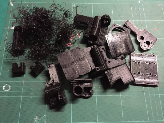
Here are a few of the failures! Modes of failure (1) loss of adhesion (2) jamming of filament (3) Windows &^&^%^& update (4) critical parts not accurate enough, especially X axis ends.
Edited 1 time(s). Last edit at 01/23/2016 04:25AM by Loska.
|
Re: Prusa i3 build log: Upgrade original Mendel January 23, 2016 04:35AM |
Registered: 8 years ago Posts: 27 |
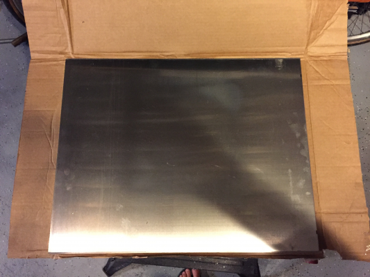
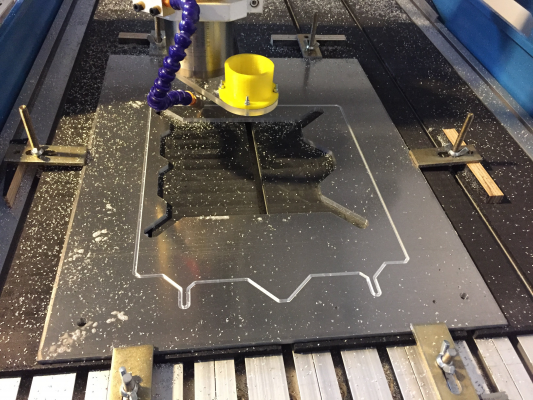
Meanwhile, a lovely plate of 6mm Aluminium arrives from an eBay store in Tasmania. You might have spotted the CNC router sitting next to the 3D printer, which I intend to put to good use!
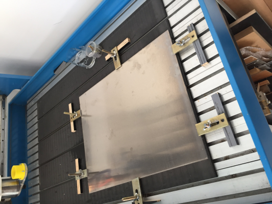
Clamped and ready .. I have made a few aluminium brackets before but this is the largest, thickest and most ambitious metal job I have run, here's hoping.
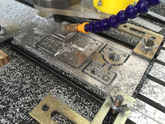
Cutting working well; 3.2mm single flute Onsrud tool, air/mist cooling, 0.5mm depth of cut. Aluminium chips raining down throughout the workshop.
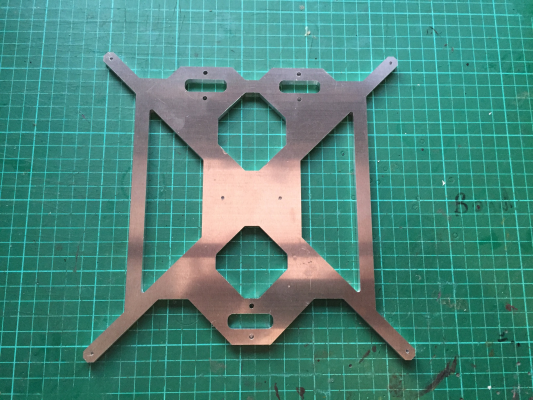
The finished parts come out really nicely, only one minor issue with a clamp slipping off (there is a telling mark on the side of the main frame) but overall I am very happy.
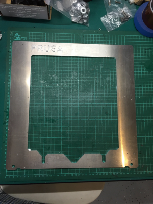
I decided to cut the Prusa logo 1.5mm deep rather than all the way through, as you need to do with Waterjet cutting. The finished edge of the CNC parts are much cleaner as well.
|
Re: Prusa i3 build log: Upgrade original Mendel January 23, 2016 12:03PM |
Registered: 10 years ago Posts: 477 |
|
Re: Prusa i3 build log: Upgrade original Mendel January 23, 2016 07:56PM |
Registered: 8 years ago Posts: 27 |
|
Re: Prusa i3 build log: Upgrade original Mendel January 25, 2016 05:50AM |
Registered: 8 years ago Posts: 27 |
My stepper motors with lead screws for the Z axis have arrived from China via AliExpress. These have TR8*2 single start, 2mm lead ACME screws that are 300mm long.
I searched around for these - a lot of the lead screws and steppers being sold for Repraps have TR8*8 lead screws which have 4 'starts' and move 8mm per turn even though they have 2mm pitch. By my calculation, those are marginal for Z axis resolution - 1 full step (not counting microstepping) would be 0.4mm. The TR8*2s will give me 0.1mm pr full step which will be better.
I also ordered a set of smooth and threaded rods - 10mm threaded for the Rework - and some M10 locking flange nuts. These nuts save the need for washers and make a satisfying 'click' as you tighten them onto printed parts.
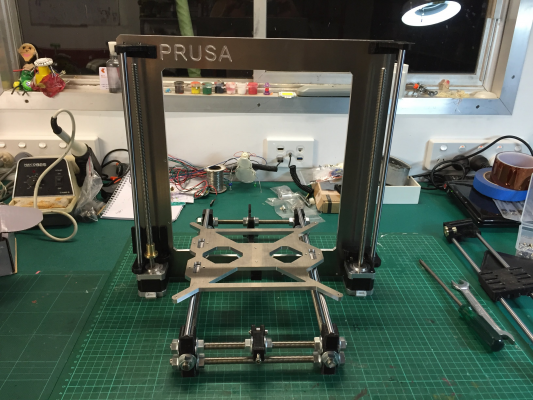
Starting to look like a printer ..
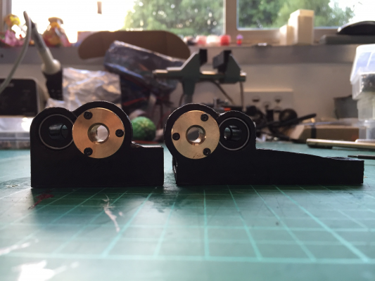
The next challenge is the X axis, and I have a problem. My lead screw nuts have a 3 hole pattern and won't fit the Rework 1.5 X ends. After trying, and failing, to modify the STL files in Solidworks (which handles this kind of geometry poorly) I give up and find some alternatives. These have a nice big boss for the nut.
Since my old Mendel seems to struggle printing accurate tall parts, the mounting tubes for the LM8UUs are wiggly and I think this is critical. I ordered a 15mm reamer so I put it to use.
Looking good!
|
Re: Prusa i3 build log: Upgrade original Mendel January 25, 2016 07:26AM |
Registered: 8 years ago Posts: 27 |
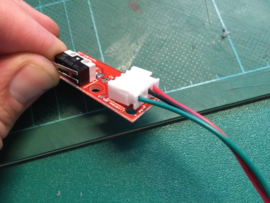
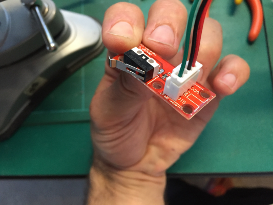
Now for wiring up. Some genius has used right angle connectors on the end-stops, right where the mounting holes are.
Fortunately I bought a pack of the JST style connectors used, so I have some upright 3-way sockets. This fix is applied to the Y and Z end-stops. Actually I will eventually retire the Z end-stop in favour of a proximity sensor but I need to set it up for now.
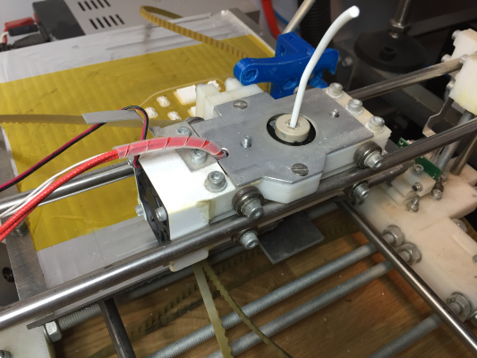
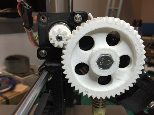
I decided to save the nice herringbone extruder gears from the Mendel. I printed these several years back from PLA and they show no signs of wear, it's good hard stuff.
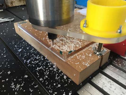
If you look closely however you will see that the big gear fouls the X carriage. Now that the Mendel is out of action, it is CNC time for a 4mm acrylic spacer.
|
Re: Prusa i3 build log: Upgrade original Mendel January 26, 2016 02:59AM |
Registered: 8 years ago Posts: 27 |
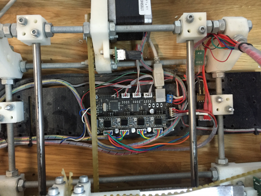
I chose to use the MKS-BASE main board, as I like that it is all-in-one rather than lots of boards plugged together. It is supposed to be completely RAMPS compatible also. I also liked the look of the RUMBA but it was a lot more expensive.
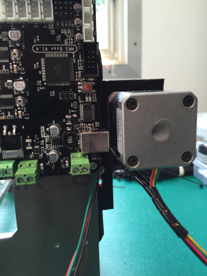
The MKS is quite a bit wider than the RAMPS however. Whilst I got around to designing a mounting bracket I used some spacers to mount it directly, then discovered a problem:
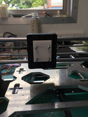
After making a dumb mistake of relocating it above the X stepper (oops, that moves!) I toyed around with spacing it out then realised my best option was to mount it perpendicular. A trip to the scrap bin turned up some child cupboard lock thingies (the offspring are mostly house trained now) which made nice instant brackets.
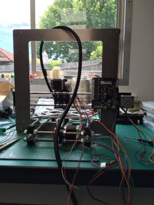
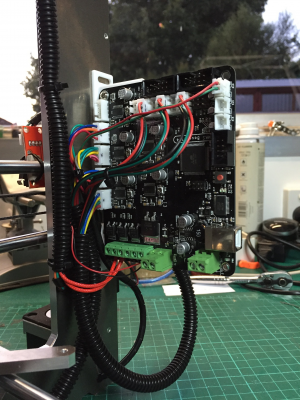
The Spaghetti Stage:
All wired up, except bed:
|
Re: Prusa i3 build log: Upgrade original Mendel January 28, 2016 05:21AM |
Registered: 8 years ago Posts: 27 |
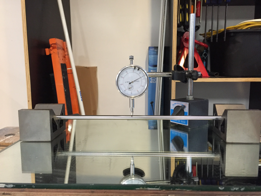
I noticed that one of my X axis smooth rods is ... well not exactly straight. Since the X ends are not very tight, I can turn the rod and watch the extruder lift up and down, maybe 1-2mm at the hot end near the bed. The other rods seem straight but it is too late to check the Y axis and I can't be bothered pulling it all apart.
I figure I can bend it back straight with a little care, and have some suitable equipment
The dial gauge and V-blocks tell me that it is about 0.5mm out in the middle on a full rotation - or 0.25mm from its axis.
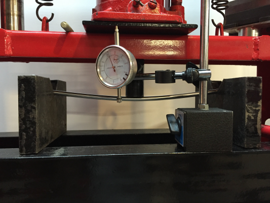
I start off carefully, deflecting the rod 0.5mm on the press. Measuring again, I see no change so I ramp it up to 1mm, then 2, 3 .. how much would you think the rod can deflect before it bends?
The answer is, about 10mm to make a change of 0.25mm which is surprising, I guess it is pretty hard stuff after all. In the end I get it within 0.1mm which I think is about as close as I can manage.
I figure I can bend it back straight with a little care, and have some suitable equipment

The dial gauge and V-blocks tell me that it is about 0.5mm out in the middle on a full rotation - or 0.25mm from its axis.
I start off carefully, deflecting the rod 0.5mm on the press. Measuring again, I see no change so I ramp it up to 1mm, then 2, 3 .. how much would you think the rod can deflect before it bends?
The answer is, about 10mm to make a change of 0.25mm which is surprising, I guess it is pretty hard stuff after all. In the end I get it within 0.1mm which I think is about as close as I can manage.
|
Re: Prusa i3 build log: Upgrade original Mendel January 28, 2016 06:10AM |
Registered: 8 years ago Posts: 27 |
One motivation to upgrade was to allow me to use a smart LCD controller. I have a little netbook dedicated to running Pronterface but it seems more convenient and reliable to print from SD - no more Windows Update in the middle of prints! My CNC router runs from a USB stick and I find that works pretty well. The old Sanguinololu only has 64k rom which is not enough to hold the LCD code.
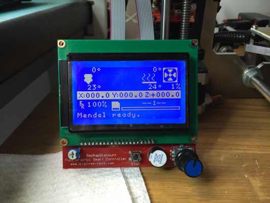
I purchased a variant of the RepRapDiscount Full Graphic Smart Controller along with my MKS-BASE motherboard. On receiving them, it looked promising, with matching 10-pin ports on both boards and ribbon cables included. I plugged them together and powered from USB to see what would happen. Well, nothing much. The screen flashed and buzzer beeped a bit randomly.
I put the LCD aside whilst I wired up the rest of the printer, then came back to it to see if I could get it working.
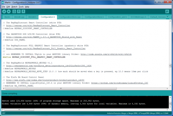
I needed to configure and compile my own firmware anyhow to set step sizes, end stops, thermistors etc. I downloaded the latest Arduino host and Marlin distribution. After checking a few guides and watching some youtube videos I had a crack at configuring and compiling for the LCD, basically by uncommenting the line '#define REPRAP_DISCOUNT_FULL_GRAPHIC_SMART_CONTROLLER'.
I also added the u8glib library using the Arduino Library Manager, which seemed like the easiest way. But this just gave me another error, unable to find utility/u8g.h I eventually figure out that there is a version of u8glib included in the Marlin distribution in 'ArduinoAddons\Arduino_1.6.x\hardware\marlin\avr\libraries' folder. Unlike the version Library manager installed, this one has a 'utility' folder containing the elusive u8g.h amongst other files. I am still a bit confused about the various library locations in Arduino but in the end I copied this u8glib to My Documents/Arduino/libraries and deleted the other u8g.lib ...
Compiled!!
I upload to the MKS-BASE, eagerly plug in the LCD controller, but get ... a flashing screen and random noises from the buzzer
Edited 1 time(s). Last edit at 01/28/2016 06:12AM by Loska.
I purchased a variant of the RepRapDiscount Full Graphic Smart Controller along with my MKS-BASE motherboard. On receiving them, it looked promising, with matching 10-pin ports on both boards and ribbon cables included. I plugged them together and powered from USB to see what would happen. Well, nothing much. The screen flashed and buzzer beeped a bit randomly.
I put the LCD aside whilst I wired up the rest of the printer, then came back to it to see if I could get it working.
I needed to configure and compile my own firmware anyhow to set step sizes, end stops, thermistors etc. I downloaded the latest Arduino host and Marlin distribution. After checking a few guides and watching some youtube videos I had a crack at configuring and compiling for the LCD, basically by uncommenting the line '#define REPRAP_DISCOUNT_FULL_GRAPHIC_SMART_CONTROLLER'.
I also added the u8glib library using the Arduino Library Manager, which seemed like the easiest way. But this just gave me another error, unable to find utility/u8g.h I eventually figure out that there is a version of u8glib included in the Marlin distribution in 'ArduinoAddons\Arduino_1.6.x\hardware\marlin\avr\libraries' folder. Unlike the version Library manager installed, this one has a 'utility' folder containing the elusive u8g.h amongst other files. I am still a bit confused about the various library locations in Arduino but in the end I copied this u8glib to My Documents/Arduino/libraries and deleted the other u8g.lib ...
Compiled!!
I upload to the MKS-BASE, eagerly plug in the LCD controller, but get ... a flashing screen and random noises from the buzzer

Edited 1 time(s). Last edit at 01/28/2016 06:12AM by Loska.
|
Re: Prusa i3 build log: Upgrade original Mendel January 29, 2016 10:27PM |
Registered: 8 years ago Posts: 27 |
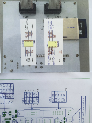
The flashing and buzzing of the LCD controller seemed like they might be caused by incorrect connection so I thought I had better check the pinouts. I had already tried swapping EXP1 and EXP2 with no better results.
I found the pinouts of the RepRapDiscount Full Graphic Smart Controller and the MKS-BASE online and compared them:
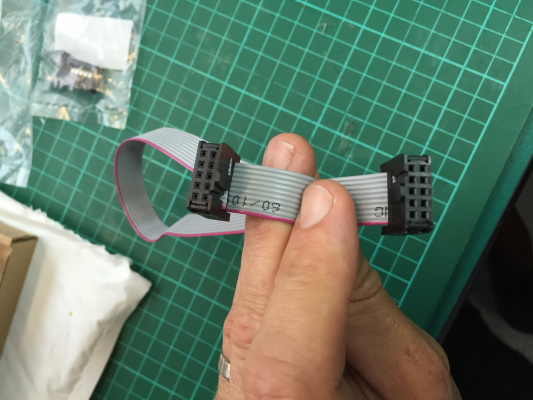
Comparing just the GND and VCC / 5V pins, you can see that they correspond here, *except* that the orientation of the sockets is actually 180 degree rotated. I have drawn in pencil where pin 1 is on the MKS-BASE. I figured that the easiest fix is to change the plugs around on the ribbon cables. These things are not designed to be re-used (I tried!) so I skipped down to Jaycar in my lunch break and picked up a couple of new connectors. Here is one of the cables, fixed:
Voila!
|
Re: Prusa i3 build log: Upgrade original Mendel January 31, 2016 06:05AM |
Registered: 8 years ago Posts: 27 |
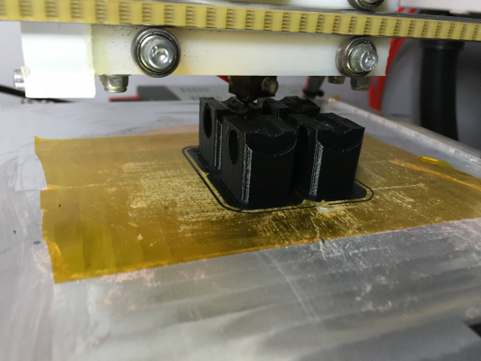
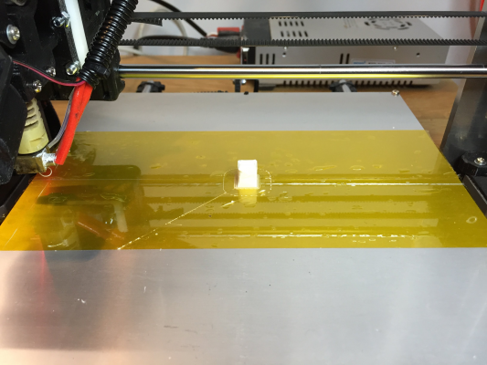
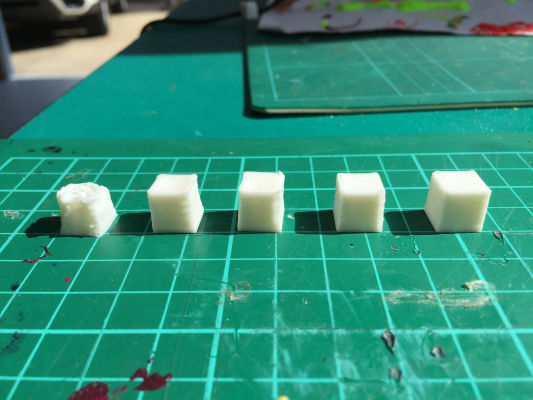
Time to get printing! Good old 10mm cubes, in PLA.
They are progressing pretty well. The first attempt was very light on material, which surprised me because I brought the settings over from the Mendel along with the guts of the extruder. Then I figured out that I had been running 8X microstepping previously, whereas the MKS BASE is hard wired for 16X. Doubling the steps per mm fixed this.
The corners were still looking a bit soft; it does help when the fan blows air over the print (mine was mounted the wrong way around!)
|
Re: Prusa i3 build log: Upgrade original Mendel January 31, 2016 06:15AM |
Registered: 8 years ago Posts: 27 |
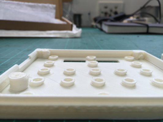
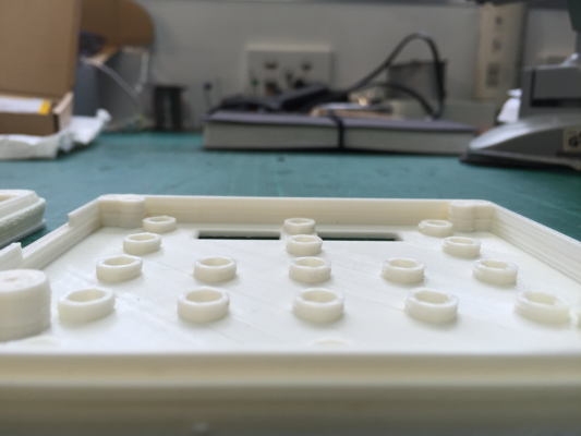
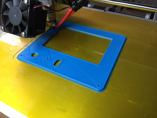
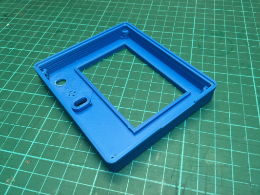
For a more challenging print, I decided to make a case for my LCD smart controller. Issues started to surface - skipping steps and misalignment between layers.
I started reducing DEFAULT_ACCELERATION, which started at 3000 mm/s/s. Bringing this down, ultimately to 1000, seemed to settle things down. I can hear the difference in smoothness as well; on the higher setting there was a little rattle, in particular from the linear bearings in the Y axis, on change of direction.
Before:
After:
|
Re: Prusa i3 build log: Upgrade original Mendel February 02, 2016 05:35AM |
Registered: 8 years ago Posts: 27 |
The next challenge is to print the top shell of the LCD smart controller case. I have some blue ABS which I have decided to use.
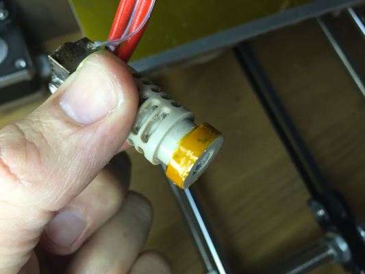
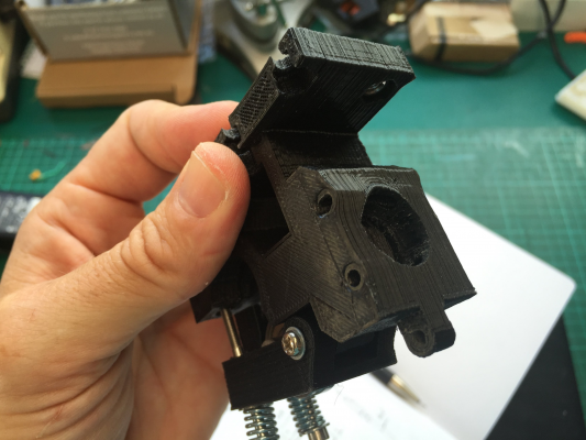
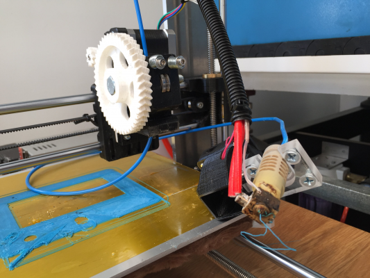
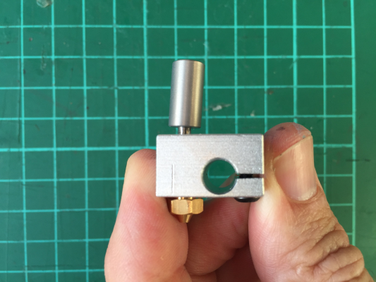
The first couple of attempts are still showing misaligned layers - reducing the acceleration settings has not entirely fixed the problem. Watching closely, I realise that the J-head hot end is able to sway in the mount (I am using the Prusa i3 Rework 1.0 greg's style extruder). It especially sways in the side-to-side direction, along the axis of the mounting screws.
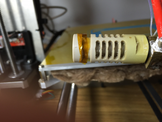
I figure that some Kapton tape wrapped around the insulator will give it a nice tight fit:
.. which it does, for a little while, until it gets hot:
Now, I am trying to print ABS at 230C using a PLA extruder body so perhaps this is not the best combination. But I add some nuts and tighten the hot end mounting screws, which not only fails to fix the problem but results in this:
Not happy
Edited 1 time(s). Last edit at 02/02/2016 05:36AM by Loska.
The first couple of attempts are still showing misaligned layers - reducing the acceleration settings has not entirely fixed the problem. Watching closely, I realise that the J-head hot end is able to sway in the mount (I am using the Prusa i3 Rework 1.0 greg's style extruder). It especially sways in the side-to-side direction, along the axis of the mounting screws.
I figure that some Kapton tape wrapped around the insulator will give it a nice tight fit:
.. which it does, for a little while, until it gets hot:
Now, I am trying to print ABS at 230C using a PLA extruder body so perhaps this is not the best combination. But I add some nuts and tighten the hot end mounting screws, which not only fails to fix the problem but results in this:
Not happy

Edited 1 time(s). Last edit at 02/02/2016 05:36AM by Loska.
|
Re: Prusa i3 build log: Upgrade original Mendel February 02, 2016 05:40AM |
Registered: 8 years ago Posts: 27 |
OK time for surgery!
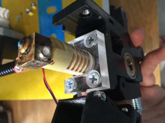
CNC prosthetic acrylic nose:
That should hold it!
Off to lunch ..
.
.
Fail!!!
CNC prosthetic acrylic nose:
That should hold it!
Off to lunch ..
.
.
Fail!!!
|
Re: Prusa i3 build log: Upgrade original Mendel February 02, 2016 05:44AM |
Registered: 8 years ago Posts: 27 |
OK I guess self tapping screws were not the best idea. I add some M3 screws, nuts and washers:
So far, so good:
Success!
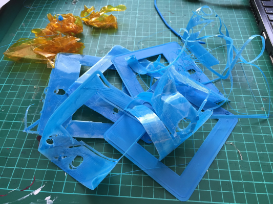
The shame file
So far, so good:
Success!
The shame file

|
Re: Prusa i3 build log: Upgrade original Mendel March 08, 2016 05:54AM |
Registered: 8 years ago Posts: 27 |
It's been a while but I have been busy! Back to the build log ...
I always intended to upgrade the i3 to dual head and auto bed levelling. Since a friend showed interest in the old Mendel I figured I would start the upgrade so I could reunite the Mendel with its J-Head and Wade extruder parts, temporarily powering the i3.
I ordered an E3D Chimera from eBay, not a real one but a reasonable looking copy (I hoped). I was very tempted to buy the real one for reasons of quality and to support the developer. But alas, with postage to Australia the cost was just too high at around AUD$300 compared to just over AUD$60 posted for the copy. (In the meantime my Forum buddy Steve pointed me here for a local Australian supplier at a reasonable cost: Chimera from Doodaddoes).
I also ordered an 8mm NPN Inductive sensor, a pair of metal MK8 style bowden extruders and some PTFE tubing.
In the meantime I set about designing an aluminium carriage. I wanted it to be all metal for accuracy and heat resistance / dispersion. I ordered some SC8UU bearings, the ones in the screw on mounting blocks.
|
Re: Prusa i3 build log: Upgrade original Mendel March 08, 2016 06:14AM |
Registered: 8 years ago Posts: 27 |
Well the Chimera copy arrived and it's not too bad. Except, one of the heat breaks came bent. The packaging was pretty decent but it may have happened in transit.
I have requested a replacement heat break from the eBay vendor but in the meantime, some gentle coaxing with the hydraulic press brought it back into line.
While I had it apart, I gave both heat breaks the polishing treatment as shown in this video: Youtube. I used metal polish rather than toothpaste
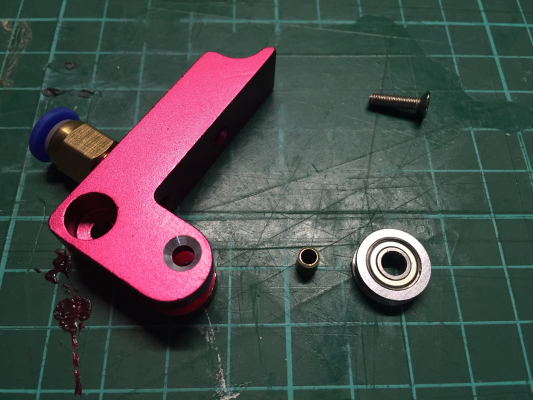
My MK8 extruders also arrived, also not too bad. But the idler bearings have a 4mm bore and sit on a 3mm screw, which would work but is not ideal, so I cut some 4mm brass tubing to make little spacers. I also countersunk the lever mount holes for a neater fit.
Here they are 'assembled' without the motors:
I have requested a replacement heat break from the eBay vendor but in the meantime, some gentle coaxing with the hydraulic press brought it back into line.
While I had it apart, I gave both heat breaks the polishing treatment as shown in this video: Youtube. I used metal polish rather than toothpaste

My MK8 extruders also arrived, also not too bad. But the idler bearings have a 4mm bore and sit on a 3mm screw, which would work but is not ideal, so I cut some 4mm brass tubing to make little spacers. I also countersunk the lever mount holes for a neater fit.
Here they are 'assembled' without the motors:
|
Re: Prusa i3 build log: Upgrade original Mendel March 08, 2016 06:24AM |
Registered: 8 years ago Posts: 27 |
Now I have all the parts to check the design, it is time to make the X-Carriage. I made a cardboard prototype first and everything seems to line up, so it is time to cut, using some leftover 6mm Aluminium from the frame.
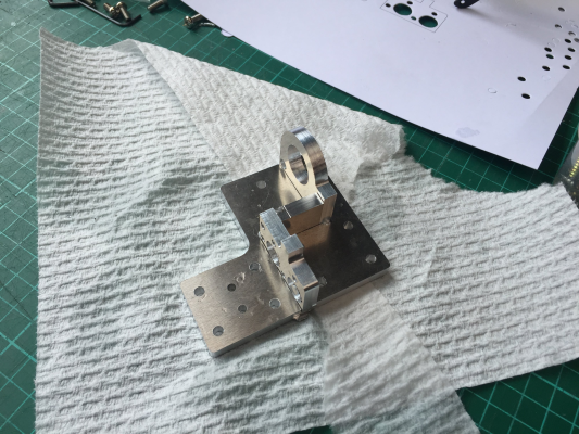
First assembly, looking shiny! Still drilling, tapping and screwing to come.
Here's how it will fit together:
The sensor is 18mm in diameter, pretty fat but it seems that the sensing distance is related to the diameter of the sensor. I wanted an 8mm distance rated sensor since the actual sensing distance is likely to be half that on an aluminium bed and I want a reasonable amount of clearance.
Edited 3 time(s). Last edit at 03/08/2016 06:27AM by Loska.
Sorry, only registered users may post in this forum.
