I3 mks gen v1.1
Posted by I3Venice
|
I3 mks gen v1.1 April 04, 2015 07:43AM |
Registered: 9 years ago Posts: 5 |
Hello everyone m quite new in here.. i have a question i build an i3 preusa kit with mks motherboard and ive istalled firmware and usb set the printer in repeiter host, the printer works fine to be honest it prints well but the z axis end the extruder are not well calibrated.. but cant change them with the gcode and cannot have access to the eeprom setting!!!!!
here a pic
Can someone help me a little bit??
here a pic
Can someone help me a little bit??
|
Re: I3 mks gen v1.1 April 04, 2015 09:06AM |
Registered: 13 years ago Posts: 1,797 |
first you should talk to your vendor before making firmware settings, as i think the board may need to be updated with a firmware that has the eeprom settings enabled.
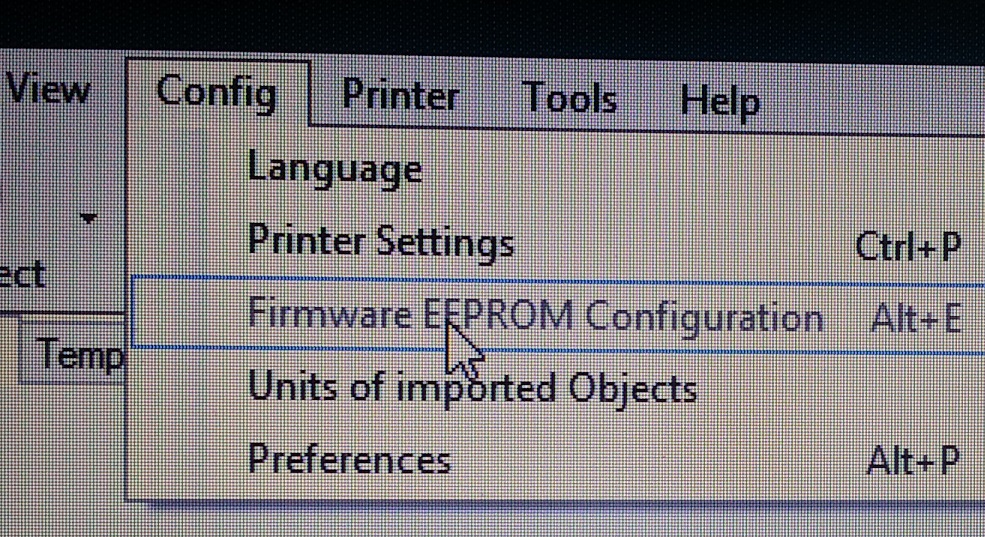
i think you need to look at repetier host printer setup. this is a start
config-> printer settings->printer and then change z axis feed rate to less than 100 mm/m
are you able to get into the eeprom settings?
since i think you cant, then they may not be editable from settings in the firmware itself. so you will need to adjust extrusion rate in software, or reload firmware. talk to the vendor you purchased printer from. different vendors give different advice.
here is how to adjust if using slic3r engine : [manual.slic3r.org]
here is how to adjust if using cura engine: [support.3dverkstan.se]
these articles were from a google search.
I would not reload firmware without knowing custom settings of vendor firmware. pin out and device settings could be different than standard setup of reprap.
the common theme here is contact your vendor.
|
Re: I3 mks gen v1.1 April 04, 2015 09:39AM |
Registered: 9 years ago Posts: 5 |
i bought it like a kit from alibaba the sunhokey prusa i3 acrilic
it has a mks gen v1.1 as motherboard and it is working but im not able to get into the eeprom and change steps mm of extruder and z axis.. i think the motherboard has some marlin firmware installed.. what would suggest me to do..??
it has a mks gen v1.1 as motherboard and it is working but im not able to get into the eeprom and change steps mm of extruder and z axis.. i think the motherboard has some marlin firmware installed.. what would suggest me to do..??
|
Re: I3 mks gen v1.1 April 04, 2015 09:44AM |
Registered: 9 years ago Posts: 5 |
|
Re: I3 mks gen v1.1 April 04, 2015 10:43AM |
Registered: 9 years ago Posts: 1,011 |
The MKS gen is an arduino mega + ramps 1.4 in a single board.
-Send M503 gCode to your printer. The printer will send all its configuration settings. Note them.
- Download the arduino software, and install it to your computer.
- Download last version of Marlin
- Make a copy of original Marlin files in a new folder (4ex. I3VeniceMarlin),
- Rename Marlin.pde and Marlin.ino with the same name as your new folder (4ex I3VeniceMarlin.pde and I3Venice.ino)
- Open I3VeniceMarlin.ino with the arduino software.
- Go to the configuration.h tab
- Change the settings with the values from the M503 command.
- Save the file, make a backup somewhere
- Now you can change whatever setting you like
- Flash the MGS gen with your modified Marlin files.
You're done. Note, you modify settings at your own risks. You should read and understand all the Marlin documentation before to start.
Edited 2 time(s). Last edit at 04/04/2015 10:46AM by Zavashier.
Collective intelligence emerges when a group of people work together effectively. Prusa i3 Folger (A lot of the parts are wrong, boring !)
|
Re: I3 mks gen v1.1 April 04, 2015 12:15PM |
Registered: 9 years ago Posts: 5 |
|
Re: I3 mks gen v1.1 April 04, 2015 12:47PM |
Registered: 9 years ago Posts: 1,011 |
I prefer the last version of Marlin, BUT, i'm expericenced with Marlin and firmware management. You'd rather try the seller's firmware first. You can flash the board with the power on.
Collective intelligence emerges when a group of people work together effectively. Prusa i3 Folger (A lot of the parts are wrong, boring !)
Collective intelligence emerges when a group of people work together effectively. Prusa i3 Folger (A lot of the parts are wrong, boring !)
|
Re: I3 mks gen v1.1 April 04, 2015 01:09PM |
Registered: 9 years ago Posts: 5 |
|
Re: I3 mks gen v1.1 April 04, 2015 04:26PM |
Registered: 9 years ago Posts: 1,011 |
If you have questions, I will certainly not be alone to awnser. There's a lot of turorials through the web. Maybe you should read and watch a bit before your first experience ?
Collective intelligence emerges when a group of people work together effectively. Prusa i3 Folger (A lot of the parts are wrong, boring !)
Collective intelligence emerges when a group of people work together effectively. Prusa i3 Folger (A lot of the parts are wrong, boring !)
|
Re: I3 mks gen v1.1 April 08, 2015 12:21PM |
Registered: 9 years ago Posts: 98 |
Hi all,
I just received my MKS gen 1.3 today. I'm going to use it on a new build. I just realized it only has one plug in for the Z axis motors. Do I just splice those wires together and use the one plug in? Seems logical but I want to make sure. I also bought 5 DRV8825's and am not clear after reading many topics on how to set the Vref for the motors. I keep seeing that its not the same as the usual drivers ( pot and common). Most reference the "via" but I have no idea what that means.
Thanks for your help.
|
Re: I3 mks gen v1.1 April 08, 2015 05:41PM |
Registered: 9 years ago Posts: 1,011 |
You have two possibilities with the MKS gen. First one, you just make a Y cable. On the Ramps, the two Z outputs are linked anyway. With a Y cable, you just do the same out of the board. I did that. Second possibility, you use the cascade output of the axis with an extra driver board and an extra driver. (as shown on the picture below) It's the state of art to do when you want to duplicate an axis. Note the cascade output is the dupont connector below the driver, not the white XH connector above the driver.
To setup a DRV8825. Be sure you set the microstepping into the required position. (the jumpers under the driver : 3 jumpers = 1/32 microsteps)
Step one, calculations.
The formula is : I(A)*8*Rs(0.1Ω for DRV8825). Find in your motor's specifications the operational amperage. Imagine it's 2A for example. The calculation is 2*8*0.1=1.76v. that's the value you want to get on your driver for that 2A motor.
Step two, motors under power
You need to get your motors into "hold" position. Set your drivers adjustable resistor to a medium position. Plug the machine to a computer through an USB cable. Turn the Printer on. Then use your software controler to move the motors on each axis, including extruder. Move them of a reasonable distance, for example 10mm, don't use small values that can put the motor on some microstepping position. Now your motors are into "hold position", so the coils are powered.
Tep three, adjust the resistor
Get a multimeter and put it into "Volt-DC" position and "20" or so resolution. Measure betwen the screw (with your red stick) and the ground pin (with your black stick). See picture below and dont pay attention to the wiring, just the screw and ground pin matters. Note, on the DRV8825 they lay at the oposite corners. Please pay attention to don't make any short with your metal sticks. Now adjust the screw to the expected voltage, preferabily with a non conductor screw driver. Turn clockwise to increase power, and counterclockwise to decrease power. Note the screw is very sensible, you may turn slowly, degree by degree. Control with multimeter between each turn. When you reach the expected voltage value, you're done.
Edited 1 time(s). Last edit at 04/08/2015 05:42PM by Zavashier.
Collective intelligence emerges when a group of people work together effectively. Prusa i3 Folger (A lot of the parts are wrong, boring !)
|
Re: I3 mks gen v1.1 April 08, 2015 06:06PM |
Registered: 9 years ago Posts: 98 |
I didn't even think of a Y cable. That's the way I'll go with that.
So these would be correct for the DRV8825?
X is .4A - set for .32
Z is 2x .4A set for .64
Y is 1.5A - set for 1.2
Extruder is .4A - set for .32
Look ok?
You didn't attach the pic you mention for the locations to check these. If you do have a pic that would be great.
Thanks
-Kevin
So these would be correct for the DRV8825?
X is .4A - set for .32
Z is 2x .4A set for .64
Y is 1.5A - set for 1.2
Extruder is .4A - set for .32
Look ok?
You didn't attach the pic you mention for the locations to check these. If you do have a pic that would be great.
Thanks
-Kevin
Quote
Zavashier
You have two possibilities with the MKS gen. First one, you just make a Y cable. On the Ramps, the two Z outputs are linked anyway. With a Y cable, you just do the same out of the board. I did that. Second possibility, you use the cascade output of the axis with an extra driver board and an extra driver. (as shown on the picture below) It's the state of art to do when you want to duplicate an axis. Note the cascade output is the dupont connector below the driver, not the white XH connector above the driver.
To setup a DRV8825. Be sure you set the microstepping into the required position. (the jumpers under the driver : 3 jumpers = 1/32 microsteps)
Step one, calculations.
The formula is : I(A)*8*Rs(0.1Ω for DRV8825). Find in your motor's specifications the operational amperage. Imagine it's 2A for example. The calculation is 2*8*0.1=1.76v. that's the value you want to get on your driver for that 2A motor.
Step two, motors under power
You need to get your motors into "hold" position. Set your drivers adjustable resistor to a medium position. Plug the machine to a computer through an USB cable. Turn the Printer on. Then use your software controler to move the motors on each axis, including extruder. Move them of a reasonable distance, for example 10mm, don't use small values that can put the motor on some microstepping position. Now your motors are into "hold position", so the coils are powered.
Tep three, adjust the resistor
Get a multimeter and put it into "Volt-DC" position and "20" or so resolution. Measure betwen the screw (with your red stick) and the ground pin (with your black stick). See picture below and dont pay attention to the wiring, just the screw and ground pin matters. Note, on the DRV8825 they lay at the oposite corners. Please pay attention to don't make any short with your metal sticks. Now adjust the screw to the expected voltage, preferabily with a non conductor screw driver. Turn clockwise to increase power, and counterclockwise to decrease power. Note the screw is very sensible, you may turn slowly, degree by degree. Control with multimeter between each turn. When you reach the expected voltage value, you're done.
|
Re: I3 mks gen v1.1 April 09, 2015 03:29AM |
Registered: 9 years ago Posts: 1,011 |
I can see the pic on both messages. Go to the MakerBase website for further information on cascade axis. About the voltage, you're right except for the Z axis. Two motors does not need to double the voltage. At home, when you plug a TV and a Fridge in your house, you don't have to change the voltage of the house, right ? 
Collective intelligence emerges when a group of people work together effectively. Prusa i3 Folger (A lot of the parts are wrong, boring !)
Collective intelligence emerges when a group of people work together effectively. Prusa i3 Folger (A lot of the parts are wrong, boring !)
|
Re: I3 mks gen v1.1 April 09, 2015 10:32AM |
Registered: 9 years ago Posts: 98 |
Quote
Zavashier
I can see the pic on both messages. Go to the MakerBase website for further information on cascade axis.
Sorry, I was referring to the picture mentioned here showing the ground pin. "Measure betwen the screw (with your red stick) and the ground pin (with your black stick). See picture below and dont pay attention to the wiring, just the screw and ground pin matters."
Quote
Zavashier
About the voltage, you're right except for the Z axis. Two motors does not need to double the voltage. At home, when you plug a TV and a Fridge in your house, you don't have to change the voltage of the house, right ?
I've read that they should be set that way for Z somewhere in another build manual.
Thanks!
|
Re: I3 mks gen v1.1 April 09, 2015 11:28AM |
Registered: 9 years ago Posts: 1,011 |
Oh, sorry, here's the picture The screw on upper left, the ground on bottom right.
Collective intelligence emerges when a group of people work together effectively. Prusa i3 Folger (A lot of the parts are wrong, boring !)
The screw on upper left, the ground on bottom right. 
Collective intelligence emerges when a group of people work together effectively. Prusa i3 Folger (A lot of the parts are wrong, boring !)
|
Re: I3 mks gen v1.1 April 09, 2015 11:32AM |
Registered: 9 years ago Posts: 98 |
Thanks!!
Quote
Zavashier
Oh, sorry, here's the picture
|
Re: I3 mks gen v1.1 April 24, 2015 06:06AM |
Registered: 8 years ago Posts: 1 |
Hi I3Venice and Forum members.
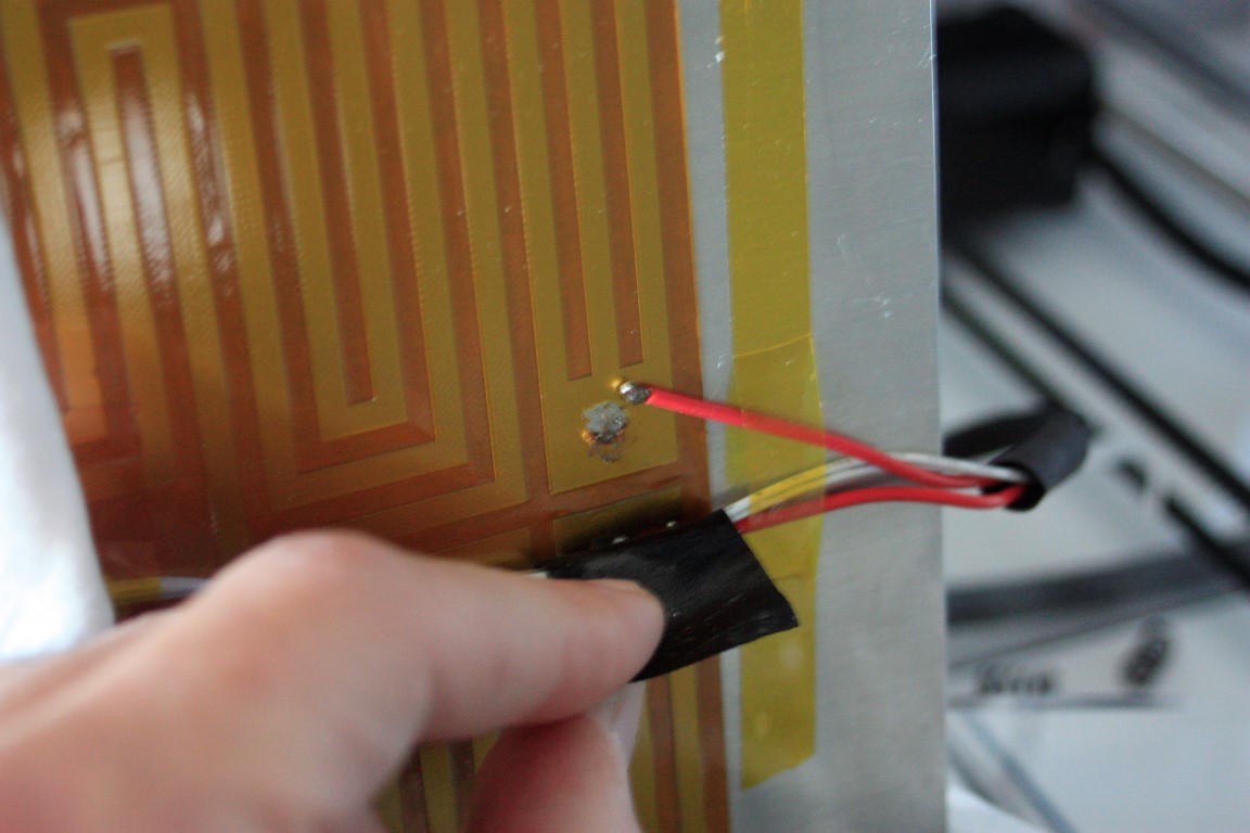
I got my Sunhokey printer. I have pass some problems with this kit starting from unsoldered wire on my heatbed (Which is a pain in the a$$ soldering it since it needs a special solder and flux) through bad nozzle and having some calibration problems mainly in the first layers and some delays in starting to extrude (You can notice by missing skirt it does....)
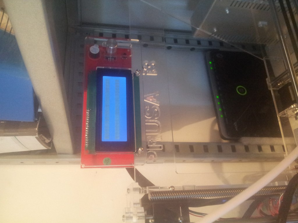
Yesterday suddenly I lost connection to computer and I notice that there is only squares appearing in the LCD.
I'm afraid that I lost the firmware. Tried to press that on board red reset button but nothing.
Any thoughts? Can you share with me I3Venice the Marlin firmware you have received from Sunhokey?
I'll much appreciate your help guys, I3Venice.
I got my Sunhokey printer. I have pass some problems with this kit starting from unsoldered wire on my heatbed (Which is a pain in the a$$ soldering it since it needs a special solder and flux) through bad nozzle and having some calibration problems mainly in the first layers and some delays in starting to extrude (You can notice by missing skirt it does....)
Yesterday suddenly I lost connection to computer and I notice that there is only squares appearing in the LCD.
I'm afraid that I lost the firmware. Tried to press that on board red reset button but nothing.
Any thoughts? Can you share with me I3Venice the Marlin firmware you have received from Sunhokey?
I'll much appreciate your help guys, I3Venice.
Quote
I3Venice
i have receveid from the revendor a updated firmware with improved feedrate should i better use this one with the arduino ide??
do i power off when fashing the moterboard?
|
Re: I3 mks gen v1.1 May 22, 2015 02:27AM |
Registered: 8 years ago Posts: 1 |
Hello guys!!
I have a mks gen v1.1 board. And i have accidently flashed an example program into my board now my original firmware is lost if anyone of you could send me the original settings. I would be highly thankful. Also i have flashed the marlin stable firmware.. and my LCD is not working. Plz help me
Edited 1 time(s). Last edit at 05/22/2015 02:27AM by Syed Zohaib Ali.
|
Re: I3 mks gen v1.1 May 22, 2015 08:47PM |
Registered: 8 years ago Posts: 2 |
|
Re: I3 mks gen v1.1 May 24, 2015 09:34AM |
Registered: 9 years ago Posts: 22 |
I suggest you study up on Marlin Firmware settings. There are many settings and it would be beyond the scope of this thread to try and expain what all of the settings do. I was somewhat intimidated when I first started off (about 6 months ago). I started using Google (insert your fav search engine here) and searched for information on Marlin settings. I also sent an email to the original seller of my printer asking if he could help me with a copy of the original firmware. He sent it within 24 hours and using a little freeware program called WinMerge I began looking at the lines of code and comparing them. I read the Wiki's to learn what each setting does and after a week or so began feeling comfortable changing settings until I had the printer working better than when it arrived. It was already printing good and needed very little tweaking but it was great to get an understanding of what each setting did. That was the main reason I bought a printer "kit" instead of a fully completed and working model. I wanted to learn. There is a huge amount of information out there for figuring this stuff out and it can be a little overwhelming at first but with patience you can get it all sorted out. Look at it as an adventure and embrace the process of learning something new. For myself this stuff is exciting and fun.
|
Re: I3 mks gen v1.1 May 24, 2015 09:39AM |
Registered: 9 years ago Posts: 22 |
I forgot to add there is a section in the Configuration.h tab that controls the LCD screen. It has to be set correctly for the type of screen you have in order for it to work. When the firmware is changed to a generic version the LCD settings as well as the settings for the steppers won't be right. You have to set the motherboard type, thermister type, LCD type, stepper settings and much much more for the new firmware to work with your particular machine.
|
Re: I3 mks gen v1.1 June 06, 2015 10:20AM |
Registered: 8 years ago Posts: 8 |
Hi!
I also buy this card with Prusa I3 kit. Unfortunately I have it partially burning when I connect it to USB.
After the accident, LCD worked but the motor is not running.
I wrote to the seller about the problem and asked to send firmware.
I think that after problems with the USB in firmware error occurred.
The seller sent me marlin and a separate Configuration.h
After flashing(usb lost, I'm flash from isp) his Marlin, LCD does not work, only two strip on the screen to adjust the contrast, which means the display controller is not initiated by Atmega.
The seller gave a description of my problem to his engineers, they still think. Probably will change the board and the motor driver.
If I get a new MKS, I'll take the firmware from MKS and will give them, but it will not be soon ...
I buy ramps and flash it marlin from the seller.
The display works. Engines not. Test firmware on ramps motor is not running.
With the latest marlin from githab same.
I am inclined to believe that the problem with the LCD not in the firmware, and that MKS and ramps still have differences and are not compatible pin to pin.
Later I want to check how the pins are connected to Atmega, to find the difference.
Inside archive marlin from the seller.
!! WARNING !!! Do not flash this firmware in the MKS
P.S. Sorry for bad english and Google translation
|
Re: I3 mks gen v1.1 June 27, 2015 01:50AM |
Registered: 8 years ago Posts: 14 |
Hi all, I am not sure if here is the right place to post, but I have been trying to reverse engineer the MKS Gen control board as supplied with my Sunhokey Prusa i3 acrylic kit.
My background is in electronics research & design for 15+ years.
My Sunhokey acrylic Prusa i3 kit was working well for a few weeks, then one day it just fried itself. There are two inductors connecting various ground plane sections to power supply ground. One of these smoked, which then screwed all 5 stepper drivers and corrupted the flash in the CPU.
I ended up at home for a couple of weeks off work so I spent quite a lot of time working out how the board is configured and reverse engineered quite a lot of it.
I noted a question in this forum topic about the Z axis steppers (there are two of them) and some comments about using a 'Y' cable to run them. This is not needed. The MKS Gen V1.1 - V1.3 have 5 stepper drivers. The 3rd one marked 'Z' and the 5th one marked 'E1' actually have their inputs connected in parallel on the circuit board. So when you tell the Z axis to do something, both the 'Z' and 'E1' outputs are mirrored. E1 should really be labelled 'Z1'. Simply use the Z and E1 outputs for your two Z axis stepper motors.
I have also modified the latest version (as of the date of this post) of Marlin firmware ready for use with this board. This only needed changes in the 'Configuration.h' and 'Configuration_adv.h' files. My unit has the 4 line by 20 character display with SD card reader and all is working well.
Some things I done on my setup - hopefully to prevent electronic problems in the future.
1. Added a wire from the earth terminal of the power supply to the 12v negative (ground) wire.
2. Upgraded the wire feeding 12V from the power supply to the MKS Gen board. (The supplied cable is really only good for a few amps!).
3. Put 2 washers behind the screws securing the power supply to the acrylic frame. The screws are just a little bit too long and could potentially create a short circuit inside the power supply.
4. Throw away the supplied LM8UU bearings and put in some better quality ones. Mine were very poor quality.
5. Print a new X carriage that uses 4 LM8UU bearings providing much better stability and hence print quality. http://www.thingiverse.com/thing:900225
6. Changed the stepper drivers to DRV8825 types (don't forget to set the current limit and remove jumpers 1_2 & 3_4 for 1/16th stepping). I set mine to 1.5 Amps.
7. Added a small 12V DC fan to the HE1 output (firmware configured) to keep the electronics and stepper driver cool. Only runs when the steppers are used, then for another minute afterwards.
Some things I am yet to do on my setup.
1. Upgrade the bed heater. The supplied one works very well for PLA, but for ABS it is not powerful enough. It struggles to get much past 90 degrees (and it takes forever to get to 90 degrees).
Other things I found...
The eeprom setting is disabled in the Sunhokey provided firmware. I enabled it in my version.
The extruder calibration was out by over 12%. When told to feed 100mm, it only fed 85mm. Initially I used some G-Code in repetier host to correct this. My setting was added to the start G-code
I occasionally find my board resets itself when I click the home key as the X carriage moves to the end stop. I think this is electrical noise getting into the processor. When I have more time I will investigate this further unless someone else has seen this problem?
Thats about all for now. If I can help anyone please ask, I will do my best to provide help if I can.
My background is in electronics research & design for 15+ years.
My Sunhokey acrylic Prusa i3 kit was working well for a few weeks, then one day it just fried itself. There are two inductors connecting various ground plane sections to power supply ground. One of these smoked, which then screwed all 5 stepper drivers and corrupted the flash in the CPU.
I ended up at home for a couple of weeks off work so I spent quite a lot of time working out how the board is configured and reverse engineered quite a lot of it.
I noted a question in this forum topic about the Z axis steppers (there are two of them) and some comments about using a 'Y' cable to run them. This is not needed. The MKS Gen V1.1 - V1.3 have 5 stepper drivers. The 3rd one marked 'Z' and the 5th one marked 'E1' actually have their inputs connected in parallel on the circuit board. So when you tell the Z axis to do something, both the 'Z' and 'E1' outputs are mirrored. E1 should really be labelled 'Z1'. Simply use the Z and E1 outputs for your two Z axis stepper motors.
I have also modified the latest version (as of the date of this post) of Marlin firmware ready for use with this board. This only needed changes in the 'Configuration.h' and 'Configuration_adv.h' files. My unit has the 4 line by 20 character display with SD card reader and all is working well.
Some things I done on my setup - hopefully to prevent electronic problems in the future.
1. Added a wire from the earth terminal of the power supply to the 12v negative (ground) wire.
2. Upgraded the wire feeding 12V from the power supply to the MKS Gen board. (The supplied cable is really only good for a few amps!).
3. Put 2 washers behind the screws securing the power supply to the acrylic frame. The screws are just a little bit too long and could potentially create a short circuit inside the power supply.
4. Throw away the supplied LM8UU bearings and put in some better quality ones. Mine were very poor quality.
5. Print a new X carriage that uses 4 LM8UU bearings providing much better stability and hence print quality. http://www.thingiverse.com/thing:900225
6. Changed the stepper drivers to DRV8825 types (don't forget to set the current limit and remove jumpers 1_2 & 3_4 for 1/16th stepping). I set mine to 1.5 Amps.
7. Added a small 12V DC fan to the HE1 output (firmware configured) to keep the electronics and stepper driver cool. Only runs when the steppers are used, then for another minute afterwards.
Some things I am yet to do on my setup.
1. Upgrade the bed heater. The supplied one works very well for PLA, but for ABS it is not powerful enough. It struggles to get much past 90 degrees (and it takes forever to get to 90 degrees).
Other things I found...
The eeprom setting is disabled in the Sunhokey provided firmware. I enabled it in my version.
The extruder calibration was out by over 12%. When told to feed 100mm, it only fed 85mm. Initially I used some G-Code in repetier host to correct this. My setting was added to the start G-code
M92 E99 ; extr cal
I occasionally find my board resets itself when I click the home key as the X carriage moves to the end stop. I think this is electrical noise getting into the processor. When I have more time I will investigate this further unless someone else has seen this problem?
Thats about all for now. If I can help anyone please ask, I will do my best to provide help if I can.
|
Re: I3 mks gen v1.1 June 27, 2015 01:52AM |
Registered: 8 years ago Posts: 14 |
|
Re: I3 mks gen v1.1 June 27, 2015 12:23PM |
Registered: 8 years ago Posts: 2 |
Quote
gjt211
I occasionally find my board resets itself when I click the home key as the X carriage moves to the end stop. I think this is electrical noise getting into the processor. When I have more time I will investigate this further unless someone else has seen this problem?
The step motors controllers need heatsinkers, and even that heat dissipation it not nearly enough for any print, the board simply will reset in between and may or may not jump to another point, ruining the print/ print quality.
My solution for it, was to directly cool it with a fan, just for all the stepper motor controllers, with an heatsink for disipation, and all was solved.
Hope this help you.
Edited 2 time(s). Last edit at 06/27/2015 12:30PM by flynn.
|
Re: I3 mks gen v1.1 June 27, 2015 07:19PM |
Registered: 8 years ago Posts: 14 |
Hi flynn,
Thanks for your response, but unfortunately this is not my problem.
This can happen within seconds of being powered on before the stepper drivers even get a chance to warm up. I also have both types of stepper drivers (A4988 & DRV8825) and it happens with either of them set at various current levels as well.
My drivers also have an 80mm fan directly cooling them as well.
Kind regards
|
Re: I3 mks gen v1.1 June 29, 2015 11:24AM |
Registered: 8 years ago Posts: 8 |
Hi!
gjt211, I want to warn against item 1. In my PSU on the case + 12V, so burned MKS when connecting a grounded PC which is connected to the body GND.
Now I have Arduino Mega + RAMPS 1.4 + new drivers.
For PC I connect via UART0 by MEGA and USB-UART with a PC side.
IMPORTANT !!! connected only RX, TX, GND. The PSU Prusa DISABLED ground PE (yellow with green stripe wire).
Perhaps I have mistake as in your p. 3.
Perhaps bolt connected case and +12V.
I'll try to unscrew the check without bolts.
Edited 1 time(s). Last edit at 06/29/2015 11:29AM by Kybb.
|
Re: I3 mks gen v1.1 July 03, 2015 02:16AM |
Registered: 9 years ago Posts: 12 |
Quote
gjt211
Some things I done on my setup - hopefully to prevent electronic problems in the future.
1. Added a wire from the earth terminal of the power supply to the 12v negative (ground) wire.
6. Changed the stepper drivers to DRV8825 types (don't forget to set the current limit and remove jumpers 1_2 & 3_4 for 1/16th stepping). I set mine to 1.5 Amps.
Other things I found...
The eeprom setting is disabled in the Sunhokey provided firmware. I enabled it in my version.
Thats about all for now. If I can help anyone please ask, I will do my best to provide help if I can.
Can I ask you for more information about 1.? My mains cable has phase, neutral and earth - you are saying connect the DC negative to AC earth?
For 6. I also have a bunch of DRV8825 drivers and would like to use them - how do you know what amp setting it is at? I just set them all to a mid-point and hope that the potentiometer's are all built the same.
And how do you enable the eeprom? I have a full copy of Marlin, I was going to take the output from a G503 command and plug that into Configuration.h - where do I change the eeprom setting?
Thanks for an informative post!
|
Re: I3 mks gen v1.1 July 03, 2015 03:43AM |
Registered: 8 years ago Posts: 14 |
Hi Ledaero,
Yes, I connected the AC earth to the DC negative. Maybe there is someone out there that can advise why this shouldn't be done. The reason I done this was just in case of earth potential rise between my PC and the MKS Gen board (which is what fried my first board). My USB cable is 5m long and now my PC and my printer have a solid earth connection between them via the AC power cable, not via the USB cable. I also noticed on another forum/post someone else who did the same thing but cant remember what forum or post.
The DRV8825 drivers will have two very low value resistors on them, you first need to find the value of these resistors (the two on one board will be the same value, typically 0.05, 0.1 or 0.2 ohms). Then you need to find out what is the current for your stepper motors, search the internet for the part number on your stepper motor you should be able to find it. Next is a calculation which is
As an example, for a current limit of 1.5A and a sense resistor of 0.1 Ohms you need to adjust the trimmer for a vref of 0.75 volts. The voltage needs to be measured between the wiper of the trimpot and ground. You will see one side of the trimpot has two tabs soldered to the circuit board and only one on the opposite side of the trimpot. This one by itself is the one where you need to measure the vref voltage.
The markings on these resistors depending on the manufacturer can vary, but should be something like R050 (for 0.05 ohms), R100 (for 0.1 ohms). On the DRV8825 board there are two of these resistors. Mine are R100.
Please note that I wouldn't go above 1.5A without ensuring a heatsink and possibly fan cooling have been added. I would recommend a small 40mm or 50mm fan mounted near the stepper drivers ensuring constant airflow over them and heatsinks.
To enable the EEPROM, in the configuration.h file locate the following;
In your code, you will see the two lines commented out. You need to remove the two backslashes from them as above. Compile then program your board.
I would have to check, but if you compile the marlin firmware there are probably quite a few other things you would need to setup for it to work. Let me know if you need some guidance.
Hope this helps and thanks for the kind words.
Yes, I connected the AC earth to the DC negative. Maybe there is someone out there that can advise why this shouldn't be done. The reason I done this was just in case of earth potential rise between my PC and the MKS Gen board (which is what fried my first board). My USB cable is 5m long and now my PC and my printer have a solid earth connection between them via the AC power cable, not via the USB cable. I also noticed on another forum/post someone else who did the same thing but cant remember what forum or post.
The DRV8825 drivers will have two very low value resistors on them, you first need to find the value of these resistors (the two on one board will be the same value, typically 0.05, 0.1 or 0.2 ohms). Then you need to find out what is the current for your stepper motors, search the internet for the part number on your stepper motor you should be able to find it. Next is a calculation which is
vref = Current limit in amps x 5 x Sense Resistor in ohmsvref is an abbreviation for 'voltage reference'
As an example, for a current limit of 1.5A and a sense resistor of 0.1 Ohms you need to adjust the trimmer for a vref of 0.75 volts. The voltage needs to be measured between the wiper of the trimpot and ground. You will see one side of the trimpot has two tabs soldered to the circuit board and only one on the opposite side of the trimpot. This one by itself is the one where you need to measure the vref voltage.
The markings on these resistors depending on the manufacturer can vary, but should be something like R050 (for 0.05 ohms), R100 (for 0.1 ohms). On the DRV8825 board there are two of these resistors. Mine are R100.
Please note that I wouldn't go above 1.5A without ensuring a heatsink and possibly fan cooling have been added. I would recommend a small 40mm or 50mm fan mounted near the stepper drivers ensuring constant airflow over them and heatsinks.
To enable the EEPROM, in the configuration.h file locate the following;
// EEPROM
// The microcontroller can store settings in the EEPROM, e.g. max velocity...
// M500 - stores parameters in EEPROM
// M501 - reads parameters from EEPROM (if you need reset them after you changed them temporarily).
// M502 - reverts to the default "factory settings".  You still need to store them in EEPROM afterwards if you want to.
//define this to enable EEPROM support
#define EEPROM_SETTINGS
//to disable EEPROM Serial responses and decrease program space by ~1700 byte: comment this out:
// please keep turned on if you can.
#define EEPROM_CHITCHAT
In your code, you will see the two lines commented out. You need to remove the two backslashes from them as above. Compile then program your board.
I would have to check, but if you compile the marlin firmware there are probably quite a few other things you would need to setup for it to work. Let me know if you need some guidance.
Hope this helps and thanks for the kind words.
|
Re: I3 mks gen v1.1 July 03, 2015 04:03AM |
Registered: 8 years ago Posts: 14 |
Hi Kybb,
Not sure why the case of your PSU is at +12v, it shouldn't be. Did you manage to find anything checking inside?
With that in mind though, I would advise anyone to use a multimeter set to ohms or continuity and measure between the positive and negative outputs and the metal case of the power supply just to check. Ensure the power is disconnected before doing this!
The way switching power supplies are designed, there should be an EMI/RFI suppression component connecting the case of the PSU to the power supply earth. In some cases this can fail and go open circuit, or even just several ohms. Saying this, the case should typically be at earth potential. If an electrician was asked to test the power supply for safety reasons, one of the tests is to perform a continuity test between the AC supply earth and any exposed metal parts (the metal case in this case). If there is no continuity the device would be marked as faulty and removed from service as unsafe. I have a test and tag licence, so hopefully I know what I am saying.
One more warning, please read this and be aware!
Switching power supplies are lethal and can kill you!
Inside every switching power supply there is a large high voltage storage capacitor or two. These will store and hold a charge of up to 350 volts DC even after the power supply has been turned off. Be warned that even days after you turn it off this voltage can still be there. So if you dismantle your power supply, be aware it can still kill you.
If you are certain you are confident and competent enough, After making sure the power is disconnected (remove the plug from the power outlet and put it in your pocket or tape it up so it cant be accidentally plugged back in), carefully dismantle your power supply, then carefully try to measure the voltage across the large storage capacitor/s. If you measure any voltage, use a 50 or 100 ohm power resistor connected to insulated probes and put one probe on one pin of the capacitor and one probe on the other, hold it there for several seconds and check the voltage with your multimeter again. Repeat if there is still some voltage present until the capacitor/s are discharged.
Hope this helps.
Kind regards

Sorry, only registered users may post in this forum.