Migbot Prusa i3 Unofficial Support Thread
Posted by jcabrer
|
Migbot Prusa i3 Unofficial Support Thread May 11, 2015 12:12PM |
Registered: 16 years ago Posts: 824 |
You know how the old saying goes: "You get what you pay for."
The Migbot Prusa i3 is one of those ridiculously inexpensive 3DPs coming from China. It has a few good things going for it. Technical support is not one of them
There is no B.O.M. per se. Only some PDFs and images to guide you in the assembly process. This isn't terrily bad if you never want to touch the pre-installed firmware, but if you are looking to upgrade to newer Marlin or Repetier code, you need to know a bit about the pulleys, belts, and lead screws. All of this information is practically non-existant, or difficult to get to. Even the pre-loaded firmware sources are unavailable... Until now.
Marlin Configuration
In the next message, I have posted the Configuration.h from the vendor supplied firmware. Many Bothans died to bring us this information.
I do not own this printer model, but I have been providing support to a friend half way across the planet, so I have learned a lot about it in a very short amount of time. Hopefully this thread will become a useful resource to the rest of you poor souls
Experimenting with Repetier Firmware
For any of you feeling adventurous, I have also provided a .json file that can be used to load initial settings into the Repetier Firmware Configuration Tool. It is not yet a working configuration due to the fact that I don't know exact coordinate system of the printer, and I am not sure about the endstop states (normally open?). If you work with this, and have any information I can correct, I will be happy to provide updates to the .json file.
Here is some of the information I need:
1. X-Axis. How far from the X-Home position to the edge of the print area?
2. Y-Axis. How far from the Y-Home position to the edge of the print area?
3. If you X-Limit installed on the right, or left. So far, my understanding is that it is on the right, but it is the MIN endstop. Is this right? If so, it means the X axis motion must be inverted.
4. These kits come with a leveling sensor. As far as I can tell, it is a non-contact of some kind, and is installed 2mm above the surface. The current .json file has autoleveling disabled. If you can figur it out for Repetier, post your results here, and I will update.
Edited 3 time(s). Last edit at 05/11/2015 12:41PM by jcabrer.
[www.thingiverse.com]
[reprap.org]
[reprap.org]
|
Re: Migbot Prusa i3 Unofficial Support Thread May 11, 2015 12:15PM |
Registered: 16 years ago Posts: 824 |
// This file is part of the pre-installed firmware that came with the Migbot Prusa i3 as recently as May 11, 2015 // It has not been thoroughly tested, so USE AT YOUR OWN RISK! #ifndef CONFIGURATION_H #define CONFIGURATION_H #include "boards.h" // This configuration file contains the basic settings. // Advanced settings can be found in Configuration_adv.h // BASIC SETTINGS: select your board type, temperature sensor type, axis scaling, and endstop configuration //=========================================================================== //============================= DELTA Printer =============================== //=========================================================================== // For a Delta printer replace the configuration files with the files in the // example_configurations/delta directory. // //=========================================================================== //============================= SCARA Printer =============================== //=========================================================================== // For a Delta printer replace the configuration files with the files in the // example_configurations/SCARA directory. // // User-specified version info of this build to display in [Pronterface, etc] terminal window during // startup. Implementation of an idea by Prof Braino to inform user that any changes made to this // build by the user have been successfully uploaded into firmware. #define STRING_VERSION_CONFIG_H __DATE__ " " __TIME__ // build date and time #define STRING_CONFIG_H_AUTHOR "(none, default config)" // Who made the changes. // SERIAL_PORT selects which serial port should be used for communication with the host. // This allows the connection of wireless adapters (for instance) to non-default port pins. // Serial port 0 is still used by the Arduino bootloader regardless of this setting. #define SERIAL_PORT 0 // This determines the communication speed of the printer #define BAUDRATE 250000 // This enables the serial port associated to the Bluetooth interface //#define BTENABLED // Enable BT interface on AT90USB devices // The following define selects which electronics board you have. // Please choose the name from boards.h that matches your setup #ifndef MOTHERBOARD #define MOTHERBOARD 33 // #define MOTHERBOARD BOARD_ULTIMAKER #endif // Define this to set a custom name for your generic Mendel, // #define CUSTOM_MENDEL_NAME "This Mendel" // Define this to set a unique identifier for this printer, (Used by some programs to differentiate between machines) // You can use an online service to generate a random UUID. (eg [www.uuidgenerator.net]) // #define MACHINE_UUID "00000000-0000-0000-0000-000000000000" // This defines the number of extruders #define EXTRUDERS 1 //// The following define selects which power supply you have. Please choose the one that matches your setup // 1 = ATX // 2 = X-Box 360 203Watts (the blue wire connected to PS_ON and the red wire to VCC) #define POWER_SUPPLY 1 // Define this to have the electronics keep the power supply off on startup. If you don't know what this is leave it. // #define PS_DEFAULT_OFF //=========================================================================== //=============================Thermal Settings ============================ //=========================================================================== // //--NORMAL IS 4.7kohm PULLUP!-- 1kohm pullup can be used on hotend sensor, using correct resistor and table // //// Temperature sensor settings: // -2 is thermocouple with MAX6675 (only for sensor 0) // -1 is thermocouple with AD595 // 0 is not used // 1 is 100k thermistor - best choice for EPCOS 100k (4.7k pullup) // 2 is 200k thermistor - ATC Semitec 204GT-2 (4.7k pullup) // 3 is Mendel-parts thermistor (4.7k pullup) // 4 is 10k thermistor !! do not use it for a hotend. It gives bad resolution at high temp. !! // 5 is 100K thermistor - ATC Semitec 104GT-2 (Used in ParCan & J-Head) (4.7k pullup) // 6 is 100k EPCOS - Not as accurate as table 1 (created using a fluke thermocouple) (4.7k pullup) // 7 is 100k Honeywell thermistor 135-104LAG-J01 (4.7k pullup) // 71 is 100k Honeywell thermistor 135-104LAF-J01 (4.7k pullup) // 8 is 100k 0603 SMD Vishay NTCS0603E3104FXT (4.7k pullup) // 9 is 100k GE Sensing AL03006-58.2K-97-G1 (4.7k pullup) // 10 is 100k RS thermistor 198-961 (4.7k pullup) // 11 is 100k beta 3950 1% thermistor (4.7k pullup) // 12 is 100k 0603 SMD Vishay NTCS0603E3104FXT (4.7k pullup) (calibrated for Makibox hot bed) // 13 is 100k Hisens 3950 1% up to 300°C for hotend "Simple ONE " & "Hotend "All In ONE" // 20 is the PT100 circuit found in the Ultimainboard V2.x // 60 is 100k Maker's Tool Works Kapton Bed Thermistor beta=3950 // // 1k ohm pullup tables - This is not normal, you would have to have changed out your 4.7k for 1k // (but gives greater accuracy and more stable PID) // 51 is 100k thermistor - EPCOS (1k pullup) // 52 is 200k thermistor - ATC Semitec 204GT-2 (1k pullup) // 55 is 100k thermistor - ATC Semitec 104GT-2 (Used in ParCan & J-Head) (1k pullup) // // 1047 is Pt1000 with 4k7 pullup // 1010 is Pt1000 with 1k pullup (non standard) // 147 is Pt100 with 4k7 pullup // 110 is Pt100 with 1k pullup (non standard) #define TEMP_SENSOR_0 1 #define TEMP_SENSOR_1 0 #define TEMP_SENSOR_2 0 #define TEMP_SENSOR_BED 1 // This makes temp sensor 1 a redundant sensor for sensor 0. If the temperatures difference between these sensors is to high the print will be aborted. //#define TEMP_SENSOR_1_AS_REDUNDANT #define MAX_REDUNDANT_TEMP_SENSOR_DIFF 10 // Actual temperature must be close to target for this long before M109 returns success #define TEMP_RESIDENCY_TIME 10 // (seconds) #define TEMP_HYSTERESIS 3 // (degC) range of +/- temperatures considered "close" to the target one #define TEMP_WINDOW 1 // (degC) Window around target to start the residency timer x degC early. // The minimal temperature defines the temperature below which the heater will not be enabled It is used // to check that the wiring to the thermistor is not broken. // Otherwise this would lead to the heater being powered on all the time. #define HEATER_0_MINTEMP 5 #define HEATER_1_MINTEMP 5 #define HEATER_2_MINTEMP 5 #define BED_MINTEMP 5 // When temperature exceeds max temp, your heater will be switched off. // This feature exists to protect your hotend from overheating accidentally, but *NOT* from thermistor short/failure! // You should use MINTEMP for thermistor short/failure protection. #define HEATER_0_MAXTEMP 275 #define HEATER_1_MAXTEMP 275 #define HEATER_2_MAXTEMP 275 #define BED_MAXTEMP 150 // If your bed has low resistance e.g. .6 ohm and throws the fuse you can duty cycle it to reduce the // average current. The value should be an integer and the heat bed will be turned on for 1 interval of // HEATER_BED_DUTY_CYCLE_DIVIDER intervals. //#define HEATER_BED_DUTY_CYCLE_DIVIDER 4 // If you want the M105 heater power reported in watts, define the BED_WATTS, and (shared for all extruders) EXTRUDER_WATTS //#define EXTRUDER_WATTS (12.0*12.0/6.7) // P=I^2/R //#define BED_WATTS (12.0*12.0/1.1) // P=I^2/R // PID settings: // Comment the following line to disable PID and enable bang-bang. #define PIDTEMP #define BANG_MAX 256 // limits current to nozzle while in bang-bang mode; 255=full current #define PID_MAX BANG_MAX // limits current to nozzle while PID is active (see PID_FUNCTIONAL_RANGE below); 255=full current #ifdef PIDTEMP //#define PID_DEBUG // Sends debug data to the serial port. //#define PID_OPENLOOP 1 // Puts PID in open loop. M104/M140 sets the output power from 0 to PID_MAX #define PID_FUNCTIONAL_RANGE 10 // If the temperature difference between the target temperature and the actual temperature // is more then PID_FUNCTIONAL_RANGE then the PID will be shut off and the heater will be set to min/max. #define PID_INTEGRAL_DRIVE_MAX PID_MAX //limit for the integral term #define K1 0.95 //smoothing factor within the PID #define PID_dT ((OVERSAMPLENR * 10.0)/(F_CPU / 64.0 / 256.0)) //sampling period of the temperature routine // If you are using a pre-configured hotend then you can use one of the value sets by uncommenting it // Ultimaker #define DEFAULT_Kp 22.2 #define DEFAULT_Ki 1.08 #define DEFAULT_Kd 114 // MakerGear // #define DEFAULT_Kp 7.0 // #define DEFAULT_Ki 0.1 // #define DEFAULT_Kd 12 // Mendel Parts V9 on 12V // #define DEFAULT_Kp 63.0 // #define DEFAULT_Ki 2.25 // #define DEFAULT_Kd 440 #endif // PIDTEMP // Bed Temperature Control // Select PID or bang-bang with PIDTEMPBED. If bang-bang, BED_LIMIT_SWITCHING will enable hysteresis // // Uncomment this to enable PID on the bed. It uses the same frequency PWM as the extruder. // If your PID_dT above is the default, and correct for your hardware/configuration, that means 7.689Hz, // which is fine for driving a square wave into a resistive load and does not significantly impact you FET heating. // This also works fine on a Fotek SSR-10DA Solid State Relay into a 250W heater. // If your configuration is significantly different than this and you don't understand the issues involved, you probably // shouldn't use bed PID until someone else verifies your hardware works. // If this is enabled, find your own PID constants below. //#define PIDTEMPBED // //#define BED_LIMIT_SWITCHING // This sets the max power delivered to the bed, and replaces the HEATER_BED_DUTY_CYCLE_DIVIDER option. // all forms of bed control obey this (PID, bang-bang, bang-bang with hysteresis) // setting this to anything other than 255 enables a form of PWM to the bed just like HEATER_BED_DUTY_CYCLE_DIVIDER did, // so you shouldn't use it unless you are OK with PWM on your bed. (see the comment on enabling PIDTEMPBED) #define MAX_BED_POWER 255 // limits duty cycle to bed; 255=full current #ifdef PIDTEMPBED //120v 250W silicone heater into 4mm borosilicate (MendelMax 1.5+) //from FOPDT model - kp=.39 Tp=405 Tdead=66, Tc set to 79.2, aggressive factor of .15 (vs .1, 1, 10) #define DEFAULT_bedKp 10.00 #define DEFAULT_bedKi .023 #define DEFAULT_bedKd 305.4 //120v 250W silicone heater into 4mm borosilicate (MendelMax 1.5+) //from pidautotune // #define DEFAULT_bedKp 97.1 // #define DEFAULT_bedKi 1.41 // #define DEFAULT_bedKd 1675.16 // FIND YOUR OWN: "M303 E-1 C8 S90" to run autotune on the bed at 90 degreesC for 8 cycles. #endif // PIDTEMPBED //this prevents dangerous Extruder moves, i.e. if the temperature is under the limit //can be software-disabled for whatever purposes by #define PREVENT_DANGEROUS_EXTRUDE //if PREVENT_DANGEROUS_EXTRUDE is on, you can still disable (uncomment) very long bits of extrusion separately. #define PREVENT_LENGTHY_EXTRUDE #define EXTRUDE_MINTEMP 170 #define EXTRUDE_MAXLENGTH (X_MAX_LENGTH+Y_MAX_LENGTH) //prevent extrusion of very large distances. /*================== Thermal Runaway Protection ============================== This is a feature to protect your printer from burn up in flames if it has a thermistor coming off place (this happened to a friend of mine recently and motivated me writing this feature). The issue: If a thermistor come off, it will read a lower temperature than actual. The system will turn the heater on forever, burning up the filament and anything else around. After the temperature reaches the target for the first time, this feature will start measuring for how long the current temperature stays below the target minus _HYSTERESIS (set_temperature - THERMAL_RUNAWAY_PROTECTION_HYSTERESIS). If it stays longer than _PERIOD, it means the thermistor temperature cannot catch up with the target, so something *may be* wrong. Then, to be on the safe side, the system will he halt. Bear in mind the count down will just start AFTER the first time the thermistor temperature is over the target, so you will have no problem if your extruder heater takes 2 minutes to hit the target on heating. */ // If you want to enable this feature for all your extruder heaters, // uncomment the 2 defines below: // Parameters for all extruder heaters //#define THERMAL_RUNAWAY_PROTECTION_PERIOD 40 //in seconds //#define THERMAL_RUNAWAY_PROTECTION_HYSTERESIS 4 // in degree Celsius // If you want to enable this feature for your bed heater, // uncomment the 2 defines below: // Parameters for the bed heater //#define THERMAL_RUNAWAY_PROTECTION_BED_PERIOD 20 //in seconds //#define THERMAL_RUNAWAY_PROTECTION_BED_HYSTERESIS 2 // in degree Celsius //=========================================================================== //=========================================================================== //=============================Mechanical Settings=========================== //=========================================================================== // Uncomment the following line to enable CoreXY kinematics // #define COREXY // coarse Endstop Settings #define ENDSTOPPULLUPS // Comment this out (using // at the start of the line) to disable the endstop pullup resistors #ifndef ENDSTOPPULLUPS // fine endstop settings: Individual pullups. will be ignored if ENDSTOPPULLUPS is defined #define ENDSTOPPULLUP_XMAX #define ENDSTOPPULLUP_YMAX #define ENDSTOPPULLUP_ZMAX #define ENDSTOPPULLUP_XMIN #define ENDSTOPPULLUP_YMIN // #define ENDSTOPPULLUP_ZMIN #endif #ifdef ENDSTOPPULLUPS #define ENDSTOPPULLUP_XMAX #define ENDSTOPPULLUP_YMAX #define ENDSTOPPULLUP_ZMAX #define ENDSTOPPULLUP_XMIN #define ENDSTOPPULLUP_YMIN // #define ENDSTOPPULLUP_ZMIN #endif // The pullups are needed if you directly connect a mechanical endswitch between the signal and ground pins. const bool X_MIN_ENDSTOP_INVERTING = true; // set to true to invert the logic of the endstop. const bool Y_MIN_ENDSTOP_INVERTING = true; // set to true to invert the logic of the endstop. const bool Z_MIN_ENDSTOP_INVERTING = true; // set to true to invert the logic of the endstop. const bool X_MAX_ENDSTOP_INVERTING = true; // set to true to invert the logic of the endstop. const bool Y_MAX_ENDSTOP_INVERTING = true; // set to true to invert the logic of the endstop. const bool Z_MAX_ENDSTOP_INVERTING = true; // set to true to invert the logic of the endstop. //#define DISABLE_MAX_ENDSTOPS //#define DISABLE_MIN_ENDSTOPS // Disable max endstops for compatibility with endstop checking routine #if defined(COREXY) && !defined(DISABLE_MAX_ENDSTOPS) #define DISABLE_MAX_ENDSTOPS #endif // For Inverting Stepper Enable Pins (Active Low) use 0, Non Inverting (Active High) use 1 #define X_ENABLE_ON 0 #define Y_ENABLE_ON 0 #define Z_ENABLE_ON 0 #define E_ENABLE_ON 0 // For all extruders // Disables axis when it's not being used. #define DISABLE_X false #define DISABLE_Y false #define DISABLE_Z false #define DISABLE_E false // For all extruders #define DISABLE_INACTIVE_EXTRUDER true //disable only inactive extruders and keep active extruder enabled #define INVERT_X_DIR true // for Mendel set to false, for Orca set to true #define INVERT_Y_DIR false // for Mendel set to true, for Orca set to false #define INVERT_Z_DIR true // for Mendel set to false, for Orca set to true #define INVERT_E0_DIR false // for direct drive extruder v9 set to true, for geared extruder set to false #define INVERT_E1_DIR false // for direct drive extruder v9 set to true, for geared extruder set to false #define INVERT_E2_DIR false // for direct drive extruder v9 set to true, for geared extruder set to false // ENDSTOP SETTINGS: // Sets direction of endstops when homing; 1=MAX, -1=MIN #define X_HOME_DIR -1 #define Y_HOME_DIR -1 #define Z_HOME_DIR -1 #define min_software_endstops true // If true, axis won't move to coordinates less than HOME_POS. #define max_software_endstops true // If true, axis won't move to coordinates greater than the defined lengths below. // Travel limits after homing #define X_MAX_POS 200 #define X_MIN_POS 0 #define Y_MAX_POS 200 #define Y_MIN_POS 0 #define Z_MAX_POS 180 #define Z_MIN_POS 0 #define X_MAX_LENGTH (X_MAX_POS - X_MIN_POS) #define Y_MAX_LENGTH (Y_MAX_POS - Y_MIN_POS) #define Z_MAX_LENGTH (Z_MAX_POS - Z_MIN_POS) //============================= Bed Auto Leveling =========================== #define ENABLE_AUTO_BED_LEVELING // Delete the comment to enable (remove // at the start of the line) #define Z_PROBE_REPEATABILITY_TEST // If not commented out, Z-Probe Repeatability test will be included if Auto Bed Leveling is Enabled. #ifdef ENABLE_AUTO_BED_LEVELING // There are 2 different ways to pick the X and Y locations to probe: // - "grid" mode // Probe every point in a rectangular grid // You must specify the rectangle, and the density of sample points // This mode is preferred because there are more measurements. // It used to be called ACCURATE_BED_LEVELING but "grid" is more descriptive // - "3-point" mode // Probe 3 arbitrary points on the bed (that aren't colinear) // You must specify the X & Y coordinates of all 3 points #define AUTO_BED_LEVELING_GRID // with AUTO_BED_LEVELING_GRID, the bed is sampled in a // AUTO_BED_LEVELING_GRID_POINTSxAUTO_BED_LEVELING_GRID_POINTS grid // and least squares solution is calculated // Note: this feature occupies 10'206 byte #ifdef AUTO_BED_LEVELING_GRID // set the rectangle in which to probe #define LEFT_PROBE_BED_POSITION -25 #define RIGHT_PROBE_BED_POSITION 175 #define BACK_PROBE_BED_POSITION 150 #define FRONT_PROBE_BED_POSITION -25 // set the number of grid points per dimension // I wouldn't see a reason to go above 3 (=9 probing points on the bed) #define AUTO_BED_LEVELING_GRID_POINTS 2 #else // not AUTO_BED_LEVELING_GRID // with no grid, just probe 3 arbitrary points. A simple cross-product // is used to esimate the plane of the print bed #define ABL_PROBE_PT_1_X 15 #define ABL_PROBE_PT_1_Y 180 #define ABL_PROBE_PT_2_X 15 #define ABL_PROBE_PT_2_Y 20 #define ABL_PROBE_PT_3_X 170 #define ABL_PROBE_PT_3_Y 20 #endif // AUTO_BED_LEVELING_GRID // these are the offsets to the probe relative to the extruder tip (Hotend - Probe) #define X_PROBE_OFFSET_FROM_EXTRUDER -20 #define Y_PROBE_OFFSET_FROM_EXTRUDER 30 #define Z_PROBE_OFFSET_FROM_EXTRUDER -0.8 #define Z_RAISE_BEFORE_HOMING 4 // (in mm) Raise Z before homing (G28) for Probe Clearance. // Be sure you have this distance over your Z_MAX_POS in case #define XY_TRAVEL_SPEED 8000 // X and Y axis travel speed between probes, in mm/min #define Z_RAISE_BEFORE_PROBING 10 //How much the extruder will be raised before traveling to the first probing point. #define Z_RAISE_BETWEEN_PROBINGS 10 //How much the extruder will be raised when traveling from between next probing points //#define Z_PROBE_SLED // turn on if you have a z-probe mounted on a sled like those designed by Charles Bell //#define SLED_DOCKING_OFFSET 5 // the extra distance the X axis must travel to pickup the sled. 0 should be fine but you can push it further if you'd like. //If defined, the Probe servo will be turned on only during movement and then turned off to avoid jerk //The value is the delay to turn the servo off after powered on - depends on the servo speed; 300ms is good value, but you can try lower it. // You MUST HAVE the SERVO_ENDSTOPS defined to use here a value higher than zero otherwise your code will not compile. // #define PROBE_SERVO_DEACTIVATION_DELAY 300 //If you have enabled the Bed Auto Leveling and are using the same Z Probe for Z Homing, //it is highly recommended you let this Z_SAFE_HOMING enabled!!! #define Z_SAFE_HOMING // This feature is meant to avoid Z homing with probe outside the bed area. // When defined, it will: // - Allow Z homing only after X and Y homing AND stepper drivers still enabled // - If stepper drivers timeout, it will need X and Y homing again before Z homing // - Position the probe in a defined XY point before Z Homing when homing all axis (G28) // - Block Z homing only when the probe is outside bed area. #ifdef Z_SAFE_HOMING #define Z_SAFE_HOMING_X_POINT -25 #define Z_SAFE_HOMING_Y_POINT -25 // #define Z_SAFE_HOMING_X_POINT (X_MAX_LENGTH/2) // X point for Z homing when homing all axis (G28) // #define Z_SAFE_HOMING_Y_POINT (Y_MAX_LENGTH/2) // Y point for Z homing when homing all axis (G28) #endif #ifdef AUTO_BED_LEVELING_GRID // Check if Probe_Offset * Grid Points is greater than Probing Range #if X_PROBE_OFFSET_FROM_EXTRUDER < 0 #if (-(X_PROBE_OFFSET_FROM_EXTRUDER * AUTO_BED_LEVELING_GRID_POINTS) >= (RIGHT_PROBE_BED_POSITION - LEFT_PROBE_BED_POSITION)) #error "The X axis probing range is not enough to fit all the points defined in AUTO_BED_LEVELING_GRID_POINTS" #endif #else #if ((X_PROBE_OFFSET_FROM_EXTRUDER * AUTO_BED_LEVELING_GRID_POINTS) >= (RIGHT_PROBE_BED_POSITION - LEFT_PROBE_BED_POSITION)) #error "The X axis probing range is not enough to fit all the points defined in AUTO_BED_LEVELING_GRID_POINTS" #endif #endif #if Y_PROBE_OFFSET_FROM_EXTRUDER < 0 #if (-(Y_PROBE_OFFSET_FROM_EXTRUDER * AUTO_BED_LEVELING_GRID_POINTS) >= (BACK_PROBE_BED_POSITION - FRONT_PROBE_BED_POSITION)) #error "The Y axis probing range is not enough to fit all the points defined in AUTO_BED_LEVELING_GRID_POINTS" #endif #else #if ((Y_PROBE_OFFSET_FROM_EXTRUDER * AUTO_BED_LEVELING_GRID_POINTS) >= (BACK_PROBE_BED_POSITION - FRONT_PROBE_BED_POSITION)) #error "The Y axis probing range is not enough to fit all the points defined in AUTO_BED_LEVELING_GRID_POINTS" #endif #endif #endif #endif // ENABLE_AUTO_BED_LEVELING // The position of the homing switches //#define MANUAL_HOME_POSITIONS // If defined, MANUAL_*_HOME_POS below will be used //#define BED_CENTER_AT_0_0 // If defined, the center of the bed is at (X=0, Y=0) //Manual homing switch locations: // For deltabots this means top and center of the Cartesian print volume. #define MANUAL_X_HOME_POS 0 #define MANUAL_Y_HOME_POS 0 #define MANUAL_Z_HOME_POS 0 //#define MANUAL_Z_HOME_POS 402 // For delta: Distance between nozzle and print surface after homing. //// MOVEMENT SETTINGS #define NUM_AXIS 4 // The axis order in all axis related arrays is X, Y, Z, E #define HOMING_FEEDRATE {50*60, 50*60, 4*60, 0} // set the homing speeds (mm/min) // default settings #define DEFAULT_AXIS_STEPS_PER_UNIT {80,80,398.269957,94.4962144} // default steps per unit for ultimaker //78.7402, 78.7402,1070,865.88 #define DEFAULT_MAX_FEEDRATE {500, 500, 5, 25} // (mm/sec) #define DEFAULT_MAX_ACCELERATION {8000,8000,100,10000} // X, Y, Z, E maximum start speed for accelerated moves. E default values are good for skeinforge 40+, for older versions raise them a lot. #define DEFAULT_ACCELERATION 3000 // X, Y, Z and E max acceleration in mm/s^2 for printing moves #define DEFAULT_RETRACT_ACCELERATION 3000 // X, Y, Z and E max acceleration in mm/s^2 for retracts // Offset of the extruders (uncomment if using more than one and relying on firmware to position when changing). // The offset has to be X=0, Y=0 for the extruder 0 hotend (default extruder). // For the other hotends it is their distance from the extruder 0 hotend. // #define EXTRUDER_OFFSET_X {0.0, 20.00} // (in mm) for each extruder, offset of the hotend on the X axis // #define EXTRUDER_OFFSET_Y {0.0, 5.00} // (in mm) for each extruder, offset of the hotend on the Y axis // The speed change that does not require acceleration (i.e. the software might assume it can be done instantaneously) #define DEFAULT_XYJERK 20.0 // (mm/sec) #define DEFAULT_ZJERK 0.4 // (mm/sec) #define DEFAULT_EJERK 5.0 // (mm/sec) //=========================================================================== //=============================Additional Features=========================== //=========================================================================== // Custom M code points #define CUSTOM_M_CODES #ifdef CUSTOM_M_CODES #define CUSTOM_M_CODE_SET_Z_PROBE_OFFSET 851 #define Z_PROBE_OFFSET_RANGE_MIN -15 #define Z_PROBE_OFFSET_RANGE_MAX -5 #endif // EEPROM // The microcontroller can store settings in the EEPROM, e.g. max velocity... // M500 - stores parameters in EEPROM // M501 - reads parameters from EEPROM (if you need reset them after you changed them temporarily). // M502 - reverts to the default "factory settings". You still need to store them in EEPROM afterwards if you want to. //define this to enable EEPROM support //#define EEPROM_SETTINGS //to disable EEPROM Serial responses and decrease program space by ~1700 byte: comment this out: // please keep turned on if you can. //#define EEPROM_CHITCHAT // Preheat Constants #define PLA_PREHEAT_HOTEND_TEMP 180 #define PLA_PREHEAT_HPB_TEMP 50 #define PLA_PREHEAT_FAN_SPEED 255 // Insert Value between 0 and 255 #define ABS_PREHEAT_HOTEND_TEMP 230 #define ABS_PREHEAT_HPB_TEMP 70 #define ABS_PREHEAT_FAN_SPEED 255 // Insert Value between 0 and 255 //LCD and SD support //#define ULTRA_LCD //general LCD support, also 16x2 //#define DOGLCD // Support for SPI LCD 128x64 (Controller ST7565R graphic Display Family) //#define SDSUPPORT // Enable SD Card Support in Hardware Console //#define SDSLOW // Use slower SD transfer mode (not normally needed - uncomment if you're getting volume init error) //#define SD_CHECK_AND_RETRY // Use CRC checks and retries on the SD communication //#define ENCODER_PULSES_PER_STEP 1 // Increase if you have a high resolution encoder //#define ENCODER_STEPS_PER_MENU_ITEM 5 // Set according to ENCODER_PULSES_PER_STEP or your liking //#define ULTIMAKERCONTROLLER //as available from the Ultimaker online store. //#define ULTIPANEL //the UltiPanel as on Thingiverse //#define LCD_FEEDBACK_FREQUENCY_HZ 1000 // this is the tone frequency the buzzer plays when on UI feedback. ie Screen Click //#define LCD_FEEDBACK_FREQUENCY_DURATION_MS 100 // the duration the buzzer plays the UI feedback sound. ie Screen Click // The MaKr3d Makr-Panel with graphic controller and SD support // [reprap.org] //#define MAKRPANEL // The RepRapDiscount Smart Controller (white PC// [reprap.org] #define REPRAP_DISCOUNT_SMART_CONTROLLER // The GADGETS3D G3D LCD/SD Controller (blue PC
|
Re: Migbot Prusa i3 Unofficial Support Thread May 11, 2015 08:56PM |
Registered: 9 years ago Posts: 112 |
|
Re: Migbot Prusa i3 Unofficial Support Thread May 15, 2015 11:45PM |
Registered: 8 years ago Posts: 16 |
Quote
jcabrer
You know how the old saying goes: "You get what you pay for."
The Migbot Prusa i3 is one of those ridiculously inexpensive 3DPs coming from China. It has a few good things going for it. Technical support is not one of them
There is no B.O.M. per se. Only some PDFs and images to guide you in the assembly process. This isn't terrily bad if you never want to touch the pre-installed firmware, but if you are looking to upgrade to newer Marlin or Repetier code, you need to know a bit about the pulleys, belts, and lead screws. All of this information is practically non-existant, or difficult to get to. Even the pre-loaded firmware sources are unavailable... Until now.
Marlin Configuration
In the next message, I have posted the Configuration.h from the vendor supplied firmware. Many Bothans died to bring us this information.
I do not own this printer model, but I have been providing support to a friend half way across the planet, so I have learned a lot about it in a very short amount of time. Hopefully this thread will become a useful resource to the rest of you poor souls
Experimenting with Repetier Firmware
For any of you feeling adventurous, I have also provided a .json file that can be used to load initial settings into the Repetier Firmware Configuration Tool. It is not yet a working configuration due to the fact that I don't know exact coordinate system of the printer, and I am not sure about the endstop states (normally open?). If you work with this, and have any information I can correct, I will be happy to provide updates to the .json file.
Here is some of the information I need:
1. X-Axis. How far from the X-Home position to the edge of the print area?
2. Y-Axis. How far from the Y-Home position to the edge of the print area?
3. If you X-Limit installed on the right, or left. So far, my understanding is that it is on the right, but it is the MIN endstop. Is this right? If so, it means the X axis motion must be inverted.
4. These kits come with a leveling sensor. As far as I can tell, it is a non-contact of some kind, and is installed 2mm above the surface. The current .json file has autoleveling disabled. If you can figur it out for Repetier, post your results here, and I will update.
Mate,
You're a legend. I've spent 3 weeks trying to get the firmware out of the clowns, and when I did get it, the file was corrupt. I'll give this a go.
cheers
|
Re: Migbot Prusa i3 Unofficial Support Thread May 15, 2015 11:58PM |
Registered: 8 years ago Posts: 16 |
Quote
evetanlm
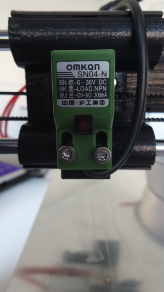
This is the Sensor they have send together but the issue is, can't sense the glass plate. maker will only say alu plate is nicer.
The sensor has a range of 2mm. The thinnest I've seen the glass is 3mm. You will probably have to find the model with a longer range. I've seen this type with a 5mm range.
[www.edata.omron.com.au]
|
Re: Migbot Prusa i3 Unofficial Support Thread May 16, 2015 12:09AM |
Registered: 8 years ago Posts: 16 |
Managed to finally get the stl files for the printed parts. If yours arrived with missing and deformed parts as mine did, you'll probably want a copy.
FYI the extruder stepper frame is available in aluminium and is worth having to contact the dealer to get one. Cost was around $8USD.
Edited 1 time(s). Last edit at 05/16/2015 04:24AM by steaneb.
FYI the extruder stepper frame is available in aluminium and is worth having to contact the dealer to get one. Cost was around $8USD.
Edited 1 time(s). Last edit at 05/16/2015 04:24AM by steaneb.
|
Re: Migbot Prusa i3 Unofficial Support Thread May 18, 2015 08:41AM |
Registered: 8 years ago Posts: 12 |
|
Re: Migbot Prusa i3 Unofficial Support Thread May 18, 2015 08:43AM |
Registered: 8 years ago Posts: 12 |
Quote
steaneb
Managed to finally get the stl files for the printed parts. If yours arrived with missing and deformed parts as mine did, you'll probably want a copy.
FYI the extruder stepper frame is available in aluminium and is worth having to contact the dealer to get one. Cost was around $8USD.
Where did you find the extruder frame in aluminium ??
|
Re: Migbot Prusa i3 Unofficial Support Thread May 18, 2015 09:47AM |
Registered: 8 years ago Posts: 16 |
Quote
magiske
Where did you find the extruder frame in aluminium ??
Contact the guys from [www.3dprintersonlinestore.com] and they should put you onto the wholesaler/ dealer. Apparently the dealer also stocks other parts, but I've never been able to get a list out of him. If you do manage I wouldn't mind a copy.
|
Re: Migbot Prusa i3 Unofficial Support Thread May 18, 2015 09:53AM |
Registered: 8 years ago Posts: 16 |
|
Re: Migbot Prusa i3 Unofficial Support Thread May 18, 2015 10:34AM |
Registered: 8 years ago Posts: 20 |
I got my Migbot a few days ago. Worked around many of the problems (bad/weak power supply, warped printed parts) The one things I cannot seem to figure out is why my z-axis motors wont work. I know the motors and wires are good but their has to be either something wrong with the motherboard or firmware....I am beginning to think it is the motherboard. Anyone else have issues with z-axis?
I have attached my Marlin Configure.h txt (I changed where they tell you place Y end stop on the motherboard, from the Y- to Y+ side).
Thanks
I have attached my Marlin Configure.h txt (I changed where they tell you place Y end stop on the motherboard, from the Y- to Y+ side).
Thanks
|
Re: Migbot Prusa i3 Unofficial Support Thread May 18, 2015 11:10AM |
Registered: 8 years ago Posts: 12 |
|
Re: Migbot Prusa i3 Unofficial Support Thread May 18, 2015 11:36AM |
Registered: 8 years ago Posts: 18 |
hi..new here and just got a migbot a few days ago. very frustrating machine because of the lackluster support. in my case the extruder motor wasn't working and the firmware appeared to be glitchy. i couldn't get cura to talk to the printer. my emails to support would go unanswered usually, so, after some research, i reflashed the board with the latest marlin firmware and thanks to jcabrer (thanks ) copied his configuration.h and downloaded arduino and crossed my fingers. suddenly cura was able to communicate with the board and the extruder was active. i still have issiues like the part isn't centered on the bed and the worse issue at the moment is when homing, the bed grinds and stutters at the Y axis, but i think its a glitchy limit switch. for anybody having similar problems, i'd suggest reflashing the board if you're comfortable with that.
|
Re: Migbot Prusa i3 Unofficial Support Thread May 18, 2015 11:42AM |
Registered: 16 years ago Posts: 824 |
|
Re: Migbot Prusa i3 Unofficial Support Thread May 18, 2015 11:54AM |
Registered: 16 years ago Posts: 824 |
You will need to configure the Start G-code section in CuraEngine. This is the built-in slicer in Repetier Host. By default, it is not the slicer selected.
The START and END g-code places commands at the front and back of the g-code of the sliced part. These instructions prepare the printer for the job.
Put the following in START
In addition, you may want to delete the contents of END, and configure the host to move to the dump area after completion/kill
Edited 1 time(s). Last edit at 05/18/2015 11:57AM by jcabrer.
The START and END g-code places commands at the front and back of the g-code of the sliced part. These instructions prepare the printer for the job.
Put the following in START
G90
G21
G28
{IF_BED}M190 S{BED}
{IF_EXT0}M104 T0 S{TEMP0}
{IF_EXT0}M109 T0 S{TEMP0}
G92 X-25 Y-55 Z0.0 E0.0
G1 X5.0 Y5.0 Z0.0 E5 F500
G1 Z0.0
G92 X5.0 Y5.0 Z0.0 E0.0
In addition, you may want to delete the contents of END, and configure the host to move to the dump area after completion/kill
Edited 1 time(s). Last edit at 05/18/2015 11:57AM by jcabrer.
|
Re: Migbot Prusa i3 Unofficial Support Thread May 18, 2015 11:59AM |
Registered: 8 years ago Posts: 18 |
|
Re: Migbot Prusa i3 Unofficial Support Thread May 18, 2015 12:07PM |
Registered: 16 years ago Posts: 824 |
Like I said, my advice only applies to Repetier Host, using CuraEngine. It also assumes that a dump area has been configured in the printer shape section that is 25mm x 55mm in the front left. YMMV with other software, but the concept of setting up the print job as I have is sound, so you should be able to wiggle it in.
|
Re: Migbot Prusa i3 Unofficial Support Thread May 18, 2015 12:51PM |
Registered: 8 years ago Posts: 16 |
Quote
tkin
The one things I cannot seem to figure out is why my z-axis motors wont work. I know the motors and wires are good but their has to be either something wrong with the motherboard or firmware....I am beginning to think it is the motherboard. Anyone else have issues with z-axis?
Can you turn both Z motors by hand easily with the power off? I found my right motor very difficult to turn, and whenever the machine tried to raise the Z axis it would stutter. I appeared that the lead screw was binding in the bushing. After disconnecting the lead screw coupler, it turns out that the vertical guide rod and motor axis are off by a few mm, which was causing the binding. I removed the right lead screw and the z axis works perfectly now. There's a tiny bit of sag, but it doesn't seem to affect quality of small prints. I haven't been able to test anything large. My prints stop after 30 minutes.
Is anyone else having problems with stopped prints?
|
Re: Migbot Prusa i3 Unofficial Support Thread May 18, 2015 01:25PM |
Registered: 16 years ago Posts: 824 |
|
Re: Migbot Prusa i3 Unofficial Support Thread May 18, 2015 02:50PM |
Registered: 8 years ago Posts: 2 |
|
Re: Migbot Prusa i3 Unofficial Support Thread May 18, 2015 03:15PM |
Registered: 8 years ago Posts: 16 |
Quote
megatoby96
Hi to all, i've problem with this printer model, when i making homing the z offset is equal at 12.35 when is at 0.2 mm from the bed, when i start printing the z axis collides against the bed... i try with g-code writed up but no work...
Are you using the proximity sensor to do auto-leveling?
|
Re: Migbot Prusa i3 Unofficial Support Thread May 18, 2015 05:14PM |
Registered: 8 years ago Posts: 2 |

|
Re: Migbot Prusa i3 Unofficial Support Thread May 18, 2015 06:26PM |
Registered: 8 years ago Posts: 16 |
I'm assuming your proximity sensor is mounted correctly (the one in the picture is upside down).
The instructions included with the printer that tell you to mount the proximity sensor 2mm higher than the extruder tip don't match the Z probe offset in the firmware. The probe should actually be < 1mm higher than the tip of the extruder.
Here's how I got mine properly setup:
The extruder shouldn't gouge the bed anymore. If anything, it might be too high, and your first layer won't stick. If it's too high you can try again so you feel more resistance on the paper in step 1.
Edit: Updated to use LED on the proximity sensor for more consistent results.
Edited 1 time(s). Last edit at 05/18/2015 09:09PM by Invictus.
The instructions included with the printer that tell you to mount the proximity sensor 2mm higher than the extruder tip don't match the Z probe offset in the firmware. The probe should actually be < 1mm higher than the tip of the extruder.
Here's how I got mine properly setup:
- Do an auto home. The LED on the sensor should be lit.
- Turn off the motors, and position the extruder nozzle over the bed
- Place a sheet of paper under the nozzle and lower the Z axis until you can feel some drag on the paper.
- Loosen the adjustment screws on the probe.
- Fold up your paper or use a thin piece of cardboard (I used a tab off the power supply box) inserted under the sensor so the LED goes off, but comes back on when you apply slight pressure.
- Hold the probe gently against the bed so that it doesn't move, and tighten the screws.
- The LED should be on, and you should be able to remove your spacer with a little drag.
- Check the extruder height again, and do a test print.
The extruder shouldn't gouge the bed anymore. If anything, it might be too high, and your first layer won't stick. If it's too high you can try again so you feel more resistance on the paper in step 1.
Edit: Updated to use LED on the proximity sensor for more consistent results.
Edited 1 time(s). Last edit at 05/18/2015 09:09PM by Invictus.
|
Re: Migbot Prusa i3 Unofficial Support Thread May 18, 2015 06:45PM |
Registered: 8 years ago Posts: 14 |
Hi All,
A great relief to see this thread. Thank you jcabrer.
My Migbot has just arrived and after unpacking it ready to be built into an epic machine, I've discovered there is no CD in the box, which after reading online; includes the manual/software/drivers.. basically the essential stuff.
(Emailed both companies.. waiting for reply)
I've built 2 reprappro mendel monos in the pass, fairly confident in constructing a 3d printer. The build from pictures online looks to be very similar to other prusa i3's, I have nosed through some of their build instructions. Yet I believe it best to start building with the correct manual.
Would anyone be able to share with me the manual/instructions? I've searched 4hrs online so far and this forum has got to be my best chance. I'd be very grateful and will then upload the manual to my website for another other poor sod without a CD.
Zurking.
|
Re: Migbot Prusa i3 Unofficial Support Thread May 18, 2015 07:56PM |
Registered: 8 years ago Posts: 16 |
Quote
Zurking
My Migbot has just arrived and after unpacking it ready to be built into an epic machine, I've discovered there is no CD in the box, which after reading online; includes the manual/software/drivers.. basically the essential stuff.
(Emailed both companies.. waiting for reply)
There's a .rar on the SD card. It took me a long time to find too. Unfortunately mine was corrupt. I got this from support: Migbot Manual & Drivers.rar
Edit: Changed link to Dropbox.
Edited 2 time(s). Last edit at 05/18/2015 10:10PM by Invictus.
|
Re: Migbot Prusa i3 Unofficial Support Thread May 18, 2015 09:03PM |
Registered: 8 years ago Posts: 100 |
Quote
Invictus
Quote
Zurking
My Migbot has just arrived and after unpacking it ready to be built into an epic machine, I've discovered there is no CD in the box, which after reading online; includes the manual/software/drivers.. basically the essential stuff.
(Emailed both companies.. waiting for reply)
There's a .rar on the SD card. It took me a long time to find too. Unfortunately mine was corrupt. I got this link from support: Auto leveling Instructions and Manuel.rar
were you able to download it? I clicked your link but there doesn't seem to be a way to download it. Mine is corrupt too, although I was able to extract many of the file it can't get through all of them before it say unexpected end to archive.
EDIT: nevermind I did a chat with 3dprintersonline and they got it to me asap. Its possible the link they send expires
Edited 1 time(s). Last edit at 05/18/2015 09:58PM by gatorNic.
|
Re: Migbot Prusa i3 Unofficial Support Thread May 18, 2015 10:31PM |
Registered: 8 years ago Posts: 19 |
|
Re: Migbot Prusa i3 Unofficial Support Thread May 19, 2015 12:44AM |
Registered: 16 years ago Posts: 824 |
Google Drive Public Share
I've created a shared folder on my google drive. I have placed the Marlin firmware there, as well as the rest of the Migbot Prusa i3 resources that are normally included on SD card.
I have also placed a pre-configured copy of the repetier firmware, along with the json file used to generate those settings. Bed leveling is turned off, as I don't have this machine, and cannot test that function. The rest of the settings were borrowed from the Marlin firmware, so they should likely work fine. That being said, if you discover an improvement, pass it along, and I will incorporate it here.
[drive.google.com]
Edited 3 time(s). Last edit at 05/19/2015 01:32AM by jcabrer.
|
Re: Migbot Prusa i3 Unofficial Support Thread May 19, 2015 01:39AM |
Registered: 8 years ago Posts: 12 |
|
Re: Migbot Prusa i3 Unofficial Support Thread May 19, 2015 01:50AM |
Registered: 16 years ago Posts: 824 |


Sorry, only registered users may post in this forum.