Migbot Prusa i3 Unofficial Support Thread
Posted by jcabrer
|
Re: Migbot Prusa i3 Unofficial Support Thread May 23, 2015 03:57PM |
Registered: 16 years ago Posts: 824 |
|
Re: Migbot Prusa i3 Unofficial Support Thread May 23, 2015 05:55PM |
Registered: 8 years ago Posts: 16 |
Quote
gatorNic
Can any of you snap a closer/better photo of the spot I circled? Its location 'L3'. Its the part that burnt out and if I identify it might be able to solder on a new one. long shot, but parts of the board are still working since when I hook up power I am still getting the lcd working which is showing the temps. Thanks
It's near impossible to get a good picture of a black part on a black PCB. There's no markings on L3 anyway.
Disclaimer: I'm a hobbyist, not an EE. Everything below is probably wrong.
L denotes an inductor and, judging from its placement between the USB connector and FTDI chip, it's a ferrite bead. It's probably rated at 500mA. I'd test the fuse at F2; you might have blown it too. I think you're lucky that the board took the hit and not your USB port. Did you run the printer without AC power connected? Is your power supply outputting significantly more than 12V? If neither, then there's likely a problem with the board, and even if you replace the blown components, it's likely to happen again unless you find the real problem.
If your power supply checks out, and if you weren't running the printer off USB-only power, I'd try to get a replacement. Sorry, man.
Edited 4 time(s). Last edit at 05/23/2015 09:18PM by Invictus.
|
Re: Migbot Prusa i3 Unofficial Support Thread May 23, 2015 09:35PM |
Registered: 8 years ago Posts: 16 |
Quote
Invictus
I'm assuming your proximity sensor is mounted correctly (the one in the picture is upside down).
The instructions included with the printer that tell you to mount the proximity sensor 2mm higher than the extruder tip don't match the Z probe offset in the firmware. The probe should actually be < 1mm higher than the tip of the extruder.
Here's how I got mine properly setup:
- Do an auto home. The LED on the sensor should be lit.
- Turn off the motors, and position the extruder nozzle over the bed
- Place a sheet of paper under the nozzle and lower the Z axis until you can feel some drag on the paper.
- Loosen the adjustment screws on the probe.
- Fold up your paper or use a thin piece of cardboard (I used a tab off the power supply box) inserted under the sensor so the LED goes off, but comes back on when you apply slight pressure.
- Hold the probe gently against the bed so that it doesn't move, and tighten the screws.
- The LED should be on, and you should be able to remove your spacer with a little drag.
- Check the extruder height again, and do a test print.
The extruder shouldn't gouge the bed anymore. If anything, it might be too high, and your first layer won't stick. If it's too high you can try again so you feel more resistance on the paper in step 1.
Edit: Updated to use LED on the proximity sensor for more consistent results.
Thanks Invictus, worth a shot. I've been loathe to drop the height of the probe due to the gouging issue you mentioned and also having the sensor mount printed part arrived deformed. I've given up hoping for a replacement from our 'helpful' mate Leo. Just waiting on a friend to print one off for me.
|
Re: Migbot Prusa i3 Unofficial Support Thread May 23, 2015 09:51PM |
Registered: 9 years ago Posts: 112 |
|
Re: Migbot Prusa i3 Unofficial Support Thread May 23, 2015 09:54PM |
Registered: 9 years ago Posts: 112 |
|
Re: Migbot Prusa i3 Unofficial Support Thread May 23, 2015 09:56PM |
Registered: 9 years ago Posts: 112 |
|
Re: Migbot Prusa i3 Unofficial Support Thread May 23, 2015 10:02PM |
Registered: 9 years ago Posts: 112 |
|
Re: Migbot Prusa i3 Unofficial Support Thread May 23, 2015 10:16PM |
Registered: 8 years ago Posts: 19 |
Quote
steaneb
Thanks Invictus, worth a shot. I've been loathe to drop the height of the probe due to the gouging issue you mentioned and also having the sensor mount printed part arrived deformed. I've given up hoping for a replacement from our 'helpful' mate Leo. Just waiting on a friend to print one off for me.
I feel your pain. I'm in a holding pattern waiting for replacement Z-axis nuts (they would not fit on the z-axis threaded rods)...
In my previous job I worked quite a bit with Chinese suppliers (as a mech eng). They are generally eager to please, but the language and cultural barrier is quite high. My approach is to let unimportant things slide, but politely and firmly insist on my rights, and I usually get my way in the end
 . The downside is of course that it takes time (both in communicating with them and waiting for replacement stuff to be sent)... Ultimately our contract is with Steve at 3D Printers Online Store, so keep him in the loop (make your pain his pain ), and if you don't get anywhere with the factory make a complaint to him. He has more influence over the factories than we have, so is more likely to get a resolution than us as individuals.
Lastly, don't forget to thank both Leo and Steve if/when they do something right. In China it's all about relationships, and while we are obviously limited in how we can build a relationship with the factory a little bit of goodwill can go a long way.
Hope this helps a bit and good luck! (I'll let you know whether my own advice helps me at all
 )
)
|
Re: Migbot Prusa i3 Unofficial Support Thread May 23, 2015 10:18PM |
Registered: 8 years ago Posts: 19 |
|
Re: Migbot Prusa i3 Unofficial Support Thread May 23, 2015 10:23PM |
Registered: 9 years ago Posts: 112 |
|
Re: Migbot Prusa i3 Unofficial Support Thread May 23, 2015 10:24PM |
Registered: 8 years ago Posts: 19 |
|
Re: Migbot Prusa i3 Unofficial Support Thread May 24, 2015 04:47PM |
Registered: 8 years ago Posts: 1 |
|
Re: Migbot Prusa i3 Unofficial Support Thread May 24, 2015 05:17PM |
Registered: 16 years ago Posts: 824 |
The following components will not fry your board if wired incorrectly, but will produce malfunctions.
1. Stepper motors.
run in wrong direction if wire order is reverse.
rattle, but do not turn if one pair of wires is reversed.
do not turn if wires are not paired correctly, or not connected.
turn in unpredictable direction if one pair is not connected.
2. Endstop limit switches.
Corresponding axis wont move if open, and configured for normally closed in firmware. Reverse is also true.
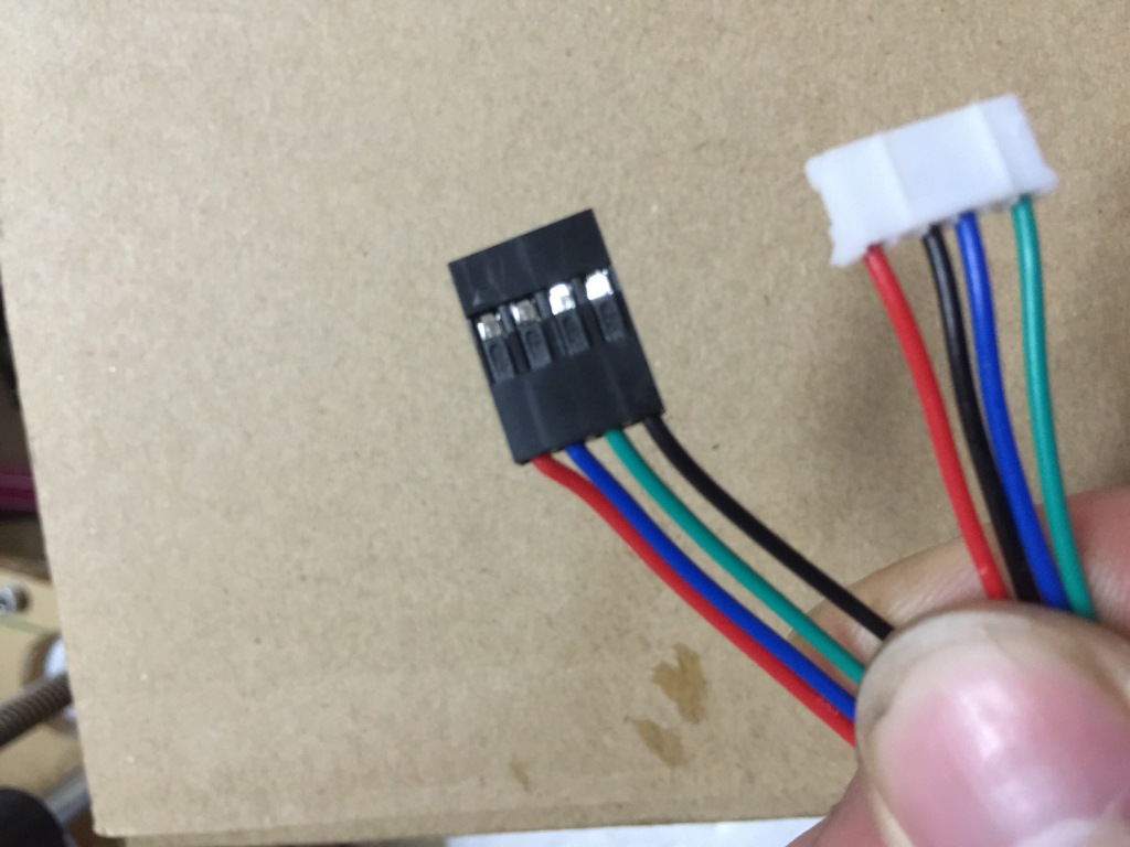
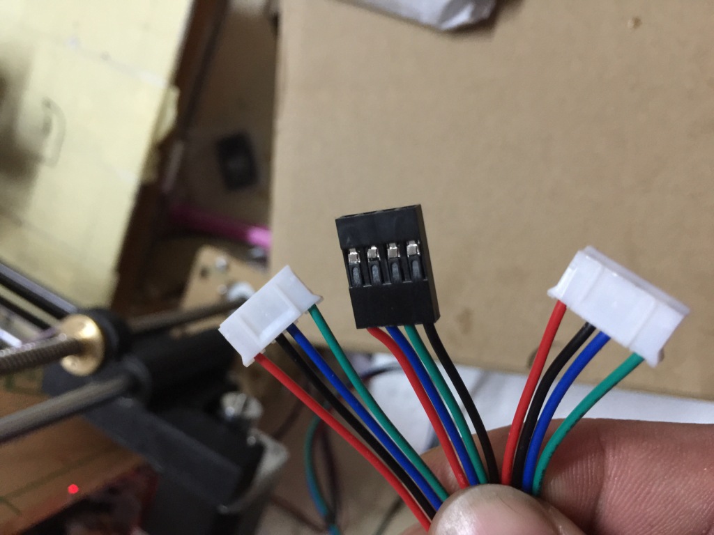
Connecting power to any component reversed WILL DEFINATELY fry something. Red is Positive, Black is Negative. Yellow is Positive.
AC and DC ARE NOT INTERCHANGEABLE. Connecting AC to anything other than L N G on the power supply will fry stuff, and probably cause a small fire.
Check all wire twice, three times even, before putting power on.
1. Stepper motors.
run in wrong direction if wire order is reverse.
rattle, but do not turn if one pair of wires is reversed.
do not turn if wires are not paired correctly, or not connected.
turn in unpredictable direction if one pair is not connected.
2. Endstop limit switches.
Corresponding axis wont move if open, and configured for normally closed in firmware. Reverse is also true.
Connecting power to any component reversed WILL DEFINATELY fry something. Red is Positive, Black is Negative. Yellow is Positive.
AC and DC ARE NOT INTERCHANGEABLE. Connecting AC to anything other than L N G on the power supply will fry stuff, and probably cause a small fire.
Check all wire twice, three times even, before putting power on.
|
Re: Migbot Prusa i3 Unofficial Support Thread May 25, 2015 04:06AM |
Registered: 9 years ago Posts: 112 |
|
Re: Migbot Prusa i3 Unofficial Support Thread May 25, 2015 04:15AM |
Registered: 9 years ago Posts: 112 |
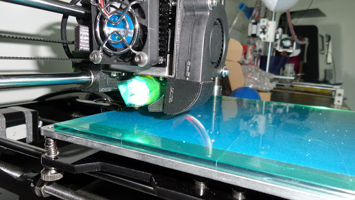
Did anyone run the test run, today first time run test run, as waiting for the tension spring from Leo, till now haven't get, so purchase from other supplier, I notice that, even after doing home and necessary adjustment, while printing the nozzle will go up itself, as the picture, can someone help see with the setting, as I really don't know the program.
|
Re: Migbot Prusa i3 Unofficial Support Thread May 25, 2015 06:38AM |
Registered: 8 years ago Posts: 14 |
Quote
Invictus
I'm assuming your proximity sensor is mounted correctly (the one in the picture is upside down).
The instructions included with the printer that tell you to mount the proximity sensor 2mm higher than the extruder tip don't match the Z probe offset in the firmware. The probe should actually be < 1mm higher than the tip of the extruder.
Here's how I got mine properly setup:
- Do an auto home. The LED on the sensor should be lit.
- Turn off the motors, and position the extruder nozzle over the bed
- Place a sheet of paper under the nozzle and lower the Z axis until you can feel some drag on the paper.
- Loosen the adjustment screws on the probe.
- Fold up your paper or use a thin piece of cardboard (I used a tab off the power supply box) inserted under the sensor so the LED goes off, but comes back on when you apply slight pressure.
- Hold the probe gently against the bed so that it doesn't move, and tighten the screws.
- The LED should be on, and you should be able to remove your spacer with a little drag.
- Check the extruder height again, and do a test print.
The extruder shouldn't gouge the bed anymore. If anything, it might be too high, and your first layer won't stick. If it's too high you can try again so you feel more resistance on the paper in step 1.
Edit: Updated to use LED on the proximity sensor for more consistent results.
Thank you for this! My printer was an engraving machine for my first few test runs. To the point where nozzle got blocked and I had to drill out the filament.
I'm used to leveling nozzles with screws and stop switches on mendels.
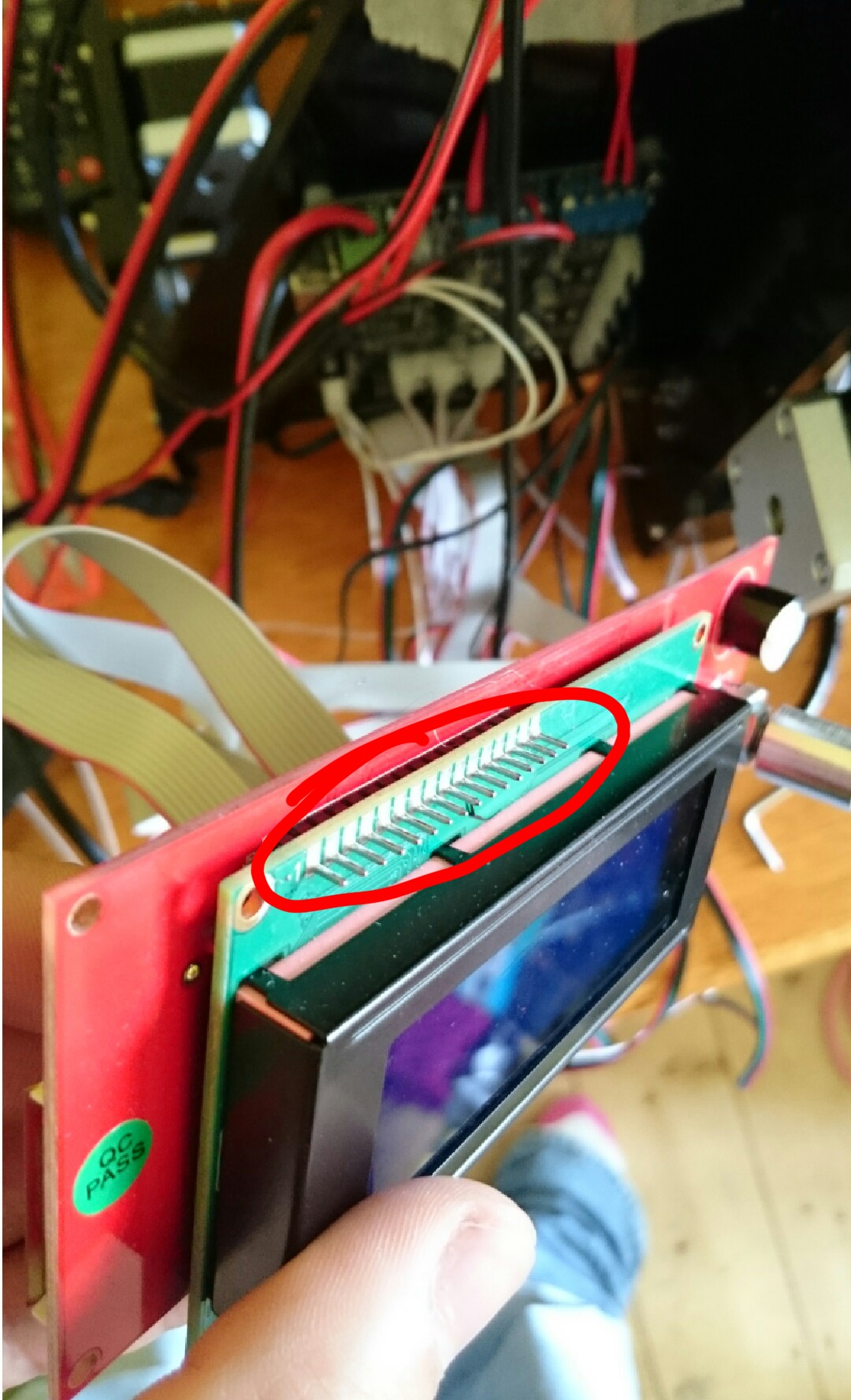
I've got a question about the LCD screen, the *prongs* above the screen are stopping it from fitting into the lazercut frame. Ive attached a photo. I wouldn't say I knew alot about electronics, but would I be able to just snip the excess off so it'll fit snuggly in the frame?
|
Re: Migbot Prusa i3 Unofficial Support Thread May 25, 2015 10:01AM |
Registered: 8 years ago Posts: 16 |
You shouldn't need to trim the leads if you're using the taller PCB spacers that came in the kit.
Snipping the excess leads off the front of the LCD is fine, though. Do it right above the solder joint. Don't try to cut flush with the board or you'll bite into the solder and may damage the joint.
Snipping the excess leads off the front of the LCD is fine, though. Do it right above the solder joint. Don't try to cut flush with the board or you'll bite into the solder and may damage the joint.
|
Re: Migbot Prusa i3 Unofficial Support Thread May 25, 2015 12:23PM |
Registered: 8 years ago Posts: 14 |
Quote
Invictus
You shouldn't need to trim the leads if you're using the taller PCB spacers that came in the kit.
Snipping the excess leads off the front of the LCD is fine, though. Do it right above the solder joint. Don't try to cut flush with the board or you'll bite into the solder and may damage the joint.
I had thought that's why they included those spacers, but then I wasn't provided with long enough bolts so wasn't sure. Okay thank you. Will get some bolts
|
Re: Migbot Prusa i3 Unofficial Support Thread May 25, 2015 02:52PM |
Registered: 8 years ago Posts: 100 |
Quote
jcabrer
The following components will not fry your board if wired incorrectly, but will produce malfunctions.
.....
Connecting power to any component reversed WILL DEFINATELY fry something. Red is Positive, Black is Negative. Yellow is Positive.
AC and DC ARE NOT INTERCHANGEABLE. Connecting AC to anything other than L N G on the power supply will fry stuff, and probably cause a small fire.
Check all wire twice, three times even, before putting power on.
Yeah was checking again today, still not seeing an issue so far. With the 12v psu hooked up ran both hotend and hotbed up to temp with the ramps lcd with no problem. Also tested the steppers with a 9v/multimeter and are working.
In testing the Voltage Regulators what should they be reading? Are they regulating 12v or 5v? I was checking out how to test via [www.learningaboutelectronics.com] These are the regulators I am looking at:

Edited 2 time(s). Last edit at 05/25/2015 02:54PM by gatorNic.
|
Re: Migbot Prusa i3 Unofficial Support Thread May 25, 2015 03:35PM |
Registered: 16 years ago Posts: 824 |
I believe the three smaller ones in green are MOSFETS. These switch on and off (-) really fast, allowing for fast PWM control of the voltage going to the Hot Ends, and Heated Bed.
The stepper motor drivers have a current adjust screw above each one. They only turn about 3/4 turn, so don't force them. Turn them all the way counter clock wise, and they will be at the lowest current. Turn all the way clockwise (don't do it), and you will be at the maximum current setting. It is very unlikely that these screws are set for you by the manufacturer, so they probably need to be adjusted. You should invest in a small flat or phillips plastic or ceramic screw driver for this. If you use a metal one, you'd better have a really steady hand.
The goal in adjusting the current of the motor drivers is that the motors can operate at the lowest setting that does not loose steps during motion, at the fastest speeds you plan on printing at. If your motors run warm, or very hot (careful), you have too much current. If it is painful to hold the motor body for more than three (3) seconds while hot, then it's too much current.
If you look closely at the screw, it has a flat on the edge. At the lowest setting, this flat is at the 7 O'clock position. You want to put it at the 9 O'clock position as a good starting point. You should never need to go beyond 12 O'clock.
The wiring looks fine. You can double-check the thermistors and make sure they are not shorted (Zero Ohms) or open (Inf). If you have a multimeter handy, then you can also check the resistance of the heated bed a,d hot end. The heated bed beds that I am familiar usually have a resistance of around 2 Ohms. The hot ends are around 7 Ohms.
Using the conversion formula
amp = volt / ohm
Hot End Amps
12v / 7 Ohms = 1.7 Amps
Heated Bed Amps
12v / 2 Ohms = 6 Amps
Why is this important? Well, for starters, it tells you how many Amps are left for driving everything else (LED lights, LCD Panel, Stepper Motor Drivers, Fans, and the Electronics).
You can look at the label on your power supply, and there should be an indication of how many Amps it supplies.
|
Re: Migbot Prusa i3 Unofficial Support Thread May 25, 2015 06:23PM |
Registered: 8 years ago Posts: 19 |
|
Re: Migbot Prusa i3 Unofficial Support Thread May 25, 2015 07:36PM |
Registered: 8 years ago Posts: 100 |
|
Re: Migbot Prusa i3 Unofficial Support Thread May 31, 2015 12:14AM |
Registered: 8 years ago Posts: 20 |
Hello all,
New to the forum and 3d printing - purchased the Migbot recently and it arrived on Wednesday. Of course the assembly guide and Cura/etc was on the SD but corrupted. I ended up here while searching for the uncorrupted files and with those I was able to successfully assemble the printer and wire the mobo/power supply. Since then it's been a hell of a frustrating couple of days trying to get it working.
Somethings I've noted on my brief journey with this printer:
1.) My LCD was in Italian; once I uploaded the lastest Marlin firmware (Using Arduino IDE) all was good
2.) Cura that comes with it is in Chinese; downloaded new version and was able to use the settings guide to get it initially set up
3.) I ordered the Autoleveler and had no success with it yet; eventually just installed the endstop for the z-axis for now
4.) X-axis and Y-axis endstop min ports on the mobo were swapped; took me a while to realize this and once that was fixed things started going better
5.) Cura will not center the build on the hotbed without adding G1 code line to move the x/y position initially in the Start G-code section (I think this is expected?)
6.) During all this a few slight gouges on the hotbed happened; extruder seems ok, but could be part of my issues below
7.) Using the supplied masking tape has let me successfully get a good first layer with the PLA that came with it
Now on to the issues I'm still working through - any input here would be appreciated
1.) Printing with an inital layer of .2 and .1 thereafter with 100% fill got me a really nice result for about the first quarter of a 20mm test cube - as it went the layers were not as complete (especially the in fill) and while it printed pretty good overall (no layer seperation but some skipping on the in fill) I know there must be something wrongly configured. I have the hotbed at 65 and the hotend at 220 - I also turned off the extruder fan as I thought it may be because the plastic was hardening too quickly.
I've played with turning down the layer and in fill speed but I haven't hit the sweet spot. I can post my Cura ini if that would help as well
2.) The printed items stick a little too well to the tape and the bottom layer rips parts of the tape off with it when trying to remove it
Thanks in advance!
Edit: I do need to check the stepper motor adjustment screws - pretty sure the X and Y are using to much current
-Chris
Edited 1 time(s). Last edit at 05/31/2015 12:29AM by CAlleman.
|
Re: Migbot Prusa i3 Unofficial Support Thread May 31, 2015 10:05AM |
Registered: 8 years ago Posts: 20 |
Hey Chris looks like you have pushed through your share of issues as well.... My suggestions for printing would be to first make sure everything is level on the bed. Check all four corners, not just the middle. You can adjust out of alignment on the X-axis by a twist to your right Z-axis stepper motor. If you cannot still get things level buy a sheet of glass to go on top. I have had good luck getting PLA to stick to the bed with PVA (about 9 parts water 1 part Elmer's glue all).
You may want to turn down you hot end temp for PLA to about 190-200.
How to PVA
[www.youtube.com]
Tom
Edited 1 time(s). Last edit at 05/31/2015 10:08AM by tkin.
You may want to turn down you hot end temp for PLA to about 190-200.
How to PVA
[www.youtube.com]
Tom
Edited 1 time(s). Last edit at 05/31/2015 10:08AM by tkin.
|
Re: Migbot Prusa i3 Unofficial Support Thread May 31, 2015 12:22PM |
Registered: 16 years ago Posts: 824 |
@Chris
it's not clear of you are printing with ABS or PLA. Either way, your temperatures are wrong.
ABS Hotend ~230°C Bed ~110°C
PLA Hotend ~180°C Bed ~70°C
These are settings I use when printing on bare glass. For PLA, must use a cooling fan. For ABS, the fan must be turned off. These two rules are well established.
I am not familiar with the hot end design on the Migbot, but if you were running PLA at 220°C, it is possible you were getting some backflow, and jamming, due to 3xcessive heat in the cold zone.
|
Re: Migbot Prusa i3 Unofficial Support Thread May 31, 2015 06:00PM |
Registered: 8 years ago Posts: 100 |
|
Re: Migbot Prusa i3 Unofficial Support Thread May 31, 2015 09:33PM |
Registered: 9 years ago Posts: 112 |
Just to update you guys on the mig bot suppliers pla temperature, I know you guys may can't believe, it cannot print at 220 degree, as it should be print at 225-230 depend on the device, as I print at prusa i3 model 230 with glass plate 70 degree, as for aluminium plate sorry it will never stick well with this suppliers one , unless with masking tape or pet tape
|
Re: Migbot Prusa i3 Unofficial Support Thread June 01, 2015 12:44PM |
Registered: 8 years ago Posts: 20 |
Hey guys,
Thanks for the input. The print bed is as level and the correct distance (using the sheet of paper trick) from the hotend all around as I can get it.
I'm printing with the supplied PLA which is a translucent blue (I also have black I can switch to) - I tried lowering the hotend temp but the print came out even worse. I tried evetanlm's suggestion of raising the temp to 225 and actually got some nice results with the hotbed at 30 with masking tape.
The only thing I need to work on is getting my filament in a good feed location and working on calibrating the extruder motor as it seems it's having issues pulling filament from the spool. If I hold the filament upright and apply a slight bit of downward force the infill is perfect and I got a nice test print...obviously I don't want to sit there and do this the whole print so I'm looking at what to change on the extruder and filament placement
Edited 1 time(s). Last edit at 06/01/2015 01:15PM by CAlleman.
|
Re: Migbot Prusa i3 Unofficial Support Thread June 01, 2015 01:21PM |
Registered: 16 years ago Posts: 824 |
Dude, you gotta stick to the correct advice, or you're going to be chasing your tail forever. Calibrate first. Not last. The reason you're having to push is due to the high temperature.
Remember that your goal is to make it print well using the correct parameters, and not the other way around. Stick to the temperature ranges I listed above, and bring everything else in to work with it. Also, don't start with 0.1mm layers. You gotta be perfect for that to work. Start with 0.4, and work you way down later.
Remember that your goal is to make it print well using the correct parameters, and not the other way around. Stick to the temperature ranges I listed above, and bring everything else in to work with it. Also, don't start with 0.1mm layers. You gotta be perfect for that to work. Start with 0.4, and work you way down later.
|
Re: Migbot Prusa i3 Unofficial Support Thread June 02, 2015 03:43AM |
Registered: 9 years ago Posts: 112 |
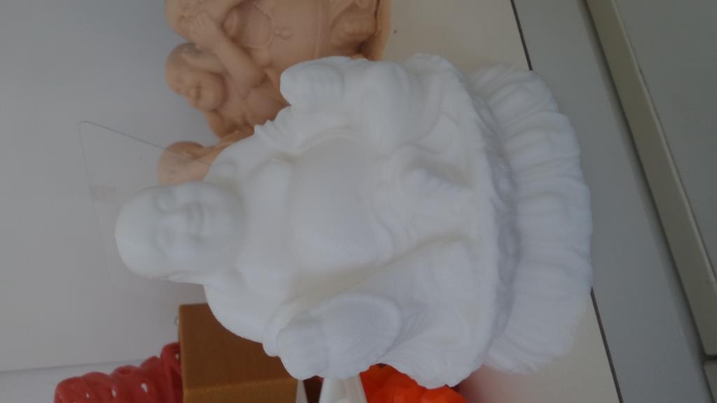
I have try to use the temperature at lower too but there is no output or the nozzle jam, I have check with the other company that are doing filament and they say the filament which migbot given is not pure filament so the temperature have to put high and not low, till now i still haven't really start print on the migbot, all these while i been using other supplier machine, which i'm tired of, as i got migbot around 1 and half month and i didn't get to start it for even one print because alot of parts are all wrong. First software can't be use, Second short tension spring, Third Wiring is wrong in a opp position. Still waiting for time to check the whole device. I'm not saying device not good but i'm just dissapointed with the supplier of all things not full and wrong. worst buy ever. I'm not cheating as attach is the filament which i got from MIgbot and i print with my other machine and it come out wonderful. I print at nozzle 235 and bed 70 with Blue Tape on 3mm glass which my side i can't get 6mm glass.


Sorry, only registered users may post in this forum.