Migbot Prusa i3 Unofficial Support Thread
Posted by jcabrer
|
Re: Migbot Prusa i3 Unofficial Support Thread June 04, 2015 06:30PM |
Registered: 16 years ago Posts: 824 |
|
Re: Migbot Prusa i3 Unofficial Support Thread June 04, 2015 07:25PM |
Registered: 8 years ago Posts: 6 |
Quote
3DST
Hello,
Thank you all so much for all the amazing information you have posted here. We just put together or Migbot Ultra Prusa i3 Diy Kit WITH the AutoLeveling Option (Proximity Sensor) from 3D Printers Online. This is the first time we have ever put together a 3D Printer. It took us roughly 4 hours to put together. It has the "MKS Base v1.3" Motherboard.
In general, everything seems to be working well when we drive it Manually. The movements along X, Y & Z seem to be fine. The Extruder and Heated Bed also heat up perfectly. And we are able to Extrude PLA perfectly. We moved the Print Bed all the way Forward, the Extruder all the way to the Right and relatively leveled to the Bed. And pressed "Set home offsets"
If we use the "Move axis" options, when we turn the dial, the Bed and Extruder move in, what we believe are the right directions. If we rotate the Dial to the Right, the Bed moves backwards till around 200 and when we turn to the Left it returns to the original position at zero. Same goes for the Y and Z. When we turn the Dial to the Right, the Y moves Left to 200 then, when we turn to the left, it goes Right back to zero. Z moves up when we turn Right, then down back to Zero when we turn it Left.
When you rotate "right", to mean in the clockwise motion correct?
I believe that the bed it supposed to move towards you when moving in the positive direction.
Quote
3DST
We calibrated the Auto-Level Proximity Sensor to be 2mm above the print head. However, we have two issues... and they are most probably related;
1. When we select "Auto Home",
a. The print bed goes ALL the way forward and starts grinding the belt teeth.
b. The Extruder moves to the Far Right
c. The Z-Axis moves DOWN... Hits the Limit Switch... but instead of stopping... it pushes the Limit Switch assembly DOWN trying to move past the Print Bed.
2. I tried setting the "Set home offsets"again. But when I try to start a print, it moves the head UP by around 4mm and begins Printing. in the Air.
I had this happen to me several times, make sure that all the switches are connected to the negative connector on the board (x-, y-, z-).
Quote
3DST
3. We received a White Wire with an LED at the end. But have NOT IDEA where to plug it in??? Not sure if this is the LED jcabrer mentioned in one of his posts.
that is not an LED, but an extra thermistor that can go in the heated bed or extruder if one of them fails; I had to replace the one in my extruder as soon as I got it, as it didn't read any signal.
Also, I cannot seem to get my extruder motor to move at all for some reason, which is really frustrating.
Edited 1 time(s). Last edit at 06/04/2015 07:26PM by keitarocos.
|
Re: Migbot Prusa i3 Unofficial Support Thread June 04, 2015 07:36PM |
Registered: 8 years ago Posts: 16 |
Thank you all again. Please forgive my ignorance. Yes, I guess it is a Thermistor, not an LED. ; )
Interestingly enough, when I control the machine manually, the Proximity Sensor LED lights up when it's supposed to. But when I try to print one of our files, it starts way above the Print Bed. However, I have a horrible feeling that my problem is that I am trying to print with x3g files created with Simply3D for a Wanhao Duplicator 4S. Something tell me that the settings are very different.
Does anyone have a functional Simplify3D "Profile" for the Migbot?
Thanks again!
|
Re: Migbot Prusa i3 Unofficial Support Thread June 04, 2015 09:38PM |
Registered: 8 years ago Posts: 3 |
Thanks for the response guys.
I checked the resistance and found that it is at 5 ohms. I read that this is supposed to be between 1 & 1.25 . . . any idea how I deal with that?? Does that mean the board is defective & I should get it replaced?
Looking at the back of the board I notice that both negative wires are connected to circuit 2 and then some solder is run over to circuit 3. See the picture.
That does't seem right to me. Shouldn't one of the negative wires run directly to circuit 3?
Mark
|
Re: Migbot Prusa i3 Unofficial Support Thread June 04, 2015 10:51PM |
Registered: 8 years ago Posts: 6 |
as far as I can tell, and see fromthe 'packing list' they gave, they're using the MK2B heat bed which uses the the following
Since the power supply that they provide is an "s-240-12" (a cheap MeanWell knockoff), providing 240 watt max at 12volts (hopfully), then the wiring is fine.
Since the power supply that they provide is an "s-240-12" (a cheap MeanWell knockoff), providing 240 watt max at 12volts (hopfully), then the wiring is fine.

|
Re: Migbot Prusa i3 Unofficial Support Thread June 05, 2015 05:49AM |
Registered: 8 years ago Posts: 20 |
Quote
3DST
1. When we select "Auto Home",
a. The print bed goes ALL the way forward and starts grinding the belt teeth.
b. The Extruder moves to the Far Right
c. The Z-Axis moves DOWN... Hits the Limit Switch... but instead of stopping... it pushes the Limit Switch assembly DOWN trying to move past the Print Bed.
2. I tried setting the "Set home offsets"again. But when I try to start a print, it moves the head UP by around 4mm and begins Printing. in the Air.
3. We received a White Wire with an LED at the end. But have NOT IDEA where to plug it in??? Not sure if this is the LED jcabrer mentioned in one of his posts.
3DST
1. a&b&c) If you are using Marlin FIRMWARE
 , Check these settings....(Ctrl+F to find)
#define INVERT_X_DIR true // for Mendel set to false, for Orca set to true
#define INVERT_Y_DIR false // for Mendel set to true, for Orca set to false
#define INVERT_Z_DIR true // for Mendel set to false, for Orca set to true
#define INVERT_E0_DIR false // for direct drive extruder v9 set to true, for geared extruder set to false
#define X_HOME_DIR -1
#define Y_HOME_DIR -1
#define Z_HOME_DIR -1
c)Also check
Z_MIN_ENDSTOP_INVERTING = true; // set to true to invert the logic of the endstop.
Check that the Z end stop is plugged into the Z- location.
Raise the extruder, then home the Z axis, and manually engage the z end stop (push with index finger).
If still nothing works, it is probably a bad ends stop, so you can try to switch one end around and try again.....or just peal back the heat shrink, inspect the wire going to the end stop, and resolder ,
2. Don't worry about the printing until you sort out the above, and level the bed.
Edited 1 time(s). Last edit at 06/05/2015 06:11AM by tkin.
|
Re: Migbot Prusa i3 Unofficial Support Thread June 05, 2015 05:56AM |
Registered: 8 years ago Posts: 20 |
@jmkslave
I ordered a new heat bed....but I thought I would try to fix my bad bed while I waited for it to arrive. I am not saying this is a good fix (it is not completely flat, and there is no guarantee it wont just fail somewhere else). I was able to lightly scrape off the outer coating of the heat bed till I seen he shinny copper inside, and then solder it.
Edited 1 time(s). Last edit at 06/05/2015 07:36AM by tkin.
|
Re: Migbot Prusa i3 Unofficial Support Thread June 05, 2015 09:15AM |
Registered: 8 years ago Posts: 3 |
Thanks for your input guys. I'm going to order a new motherboard, as Leo went radio silent on me. I figure that I'm going to be making more printers anyway, and getting mine replaced will take a long time. Which motherboard do you recommend I buy, and where from? I have no soldering equipment, by the way.
|
Re: Migbot Prusa i3 Unofficial Support Thread June 05, 2015 02:11PM |
Registered: 8 years ago Posts: 18 |
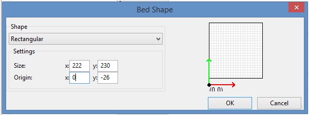
well, i've been so busy making mods and prototyping stuff, i didn't have time until now to try and figure out the bed centering issue. i tried the lines from jcabrer but the printer would auto level and at the point where it pauses ..then starts to print....nothing. i've tried inserting a G1 line corresponding to where i thought the print head should go..but it doesn't go there. if you take the entire heatbed in account (220x220), my x axis center is 95 and y axis is 100. when homed: x axis -5 y axis -55 z axis .8 has anybody soved this problem? on another note, i'll post pics soon of my setup (if anyone is interested) of the mods i've done. btw, printing on glass iz da bomb.
|
Re: Migbot Prusa i3 Unofficial Support Thread June 05, 2015 05:09PM |
Registered: 16 years ago Posts: 824 |
|
Re: Migbot Prusa i3 Unofficial Support Thread June 05, 2015 07:21PM |
Registered: 8 years ago Posts: 80 |
My experience with the Migbot. Thermistor in the hot end was shorted by the allen screw, Took it out, measured resistance and was ok. Put some thermal paste on it and watched the tightening of the screw. Right side Z axis mount was bad. Screw would bind. leveled the screw holder. X,Y and Z axis now run free. Heater bed would not heat up very fast. Voltage dropped to 9 volts when on leading to a very weak power supply. Ordered a 30 amp and a 40 amp to see differences.
|
Re: Migbot Prusa i3 Unofficial Support Thread June 06, 2015 06:13AM |
Registered: 8 years ago Posts: 20 |
Quote
rejaak
.... try and figure out the bed centering issue. ...
I have had similar confusion between Marlin, Pronterface, and Slic3r. Jcaber correct me if my understanding is wrong.
In Marlin you set travel limits: once you hit your end stop how far you can move.
Pronterface: just lets you move freely (that button which which appears to center your extruder just moves +100 X & Y)
Slic3r (or Cura): this is where you set you bed size, and the center of where you print
First you have to get you X & Y motor steps per mm right (Move 100mm in Pronterface, measure how far you actually move, take the measured number divide by 100-=__%) Take __% and multiply by the corresponding axis value in Marlin. Enter new value in Marlin and reflash...check again.
#define DEFAULT_AXIS_STEPS_PER_UNIT {81.7,81.7,404,100} (Values are X,Y,Z,E)
Note: I am not sure how well all this will scale with the Migbot( you might be dead on at 100mm but off at 10mm)
Once your steps per mm are right, in pronterface count how far from you home location to edge of the bed, and total bed size.
Enter into Slic3r. (my values will differ from yours because I am using a glass bed)
Edited 2 time(s). Last edit at 06/06/2015 06:38AM by tkin.
|
Re: Migbot Prusa i3 Unofficial Support Thread June 06, 2015 06:29AM |
Registered: 8 years ago Posts: 20 |
@Putzer,
I don't know if "More Power!" is going to be the best solution. Electricity can be described to flow like water. If you are trying to flow too much through too small of pipes you get back pressure. With water pipes, they rupture, for electricity, things overheat, melt, and catch fire. If you received the same tiny power cable going the PSU that I did, I would first replace it before anything. You may also find the original heat bed wont handle the added amps.
I don't know if "More Power!" is going to be the best solution. Electricity can be described to flow like water. If you are trying to flow too much through too small of pipes you get back pressure. With water pipes, they rupture, for electricity, things overheat, melt, and catch fire. If you received the same tiny power cable going the PSU that I did, I would first replace it before anything. You may also find the original heat bed wont handle the added amps.
|
Re: Migbot Prusa i3 Unofficial Support Thread June 06, 2015 09:24AM |
Registered: 8 years ago Posts: 16 |
Quote
Putzer
Right side Z axis mount was bad. Screw would bind. leveled the screw holder. X,Y and Z axis now run free.
Can you describe in more detail how you resloved the binding? My right-side lead screw binds too. If I remove the lead screw from the coupler it turns freely in the bushing. The motor is also working. I've tried loosening different parts, and making sure everything is leveled and aligned, but every time I tighten it back up it'll move about a few mm then start binding again.
|
Re: Migbot Prusa i3 Unofficial Support Thread June 06, 2015 10:36AM |
Registered: 8 years ago Posts: 80 |
@tkin My printer came with heavy wires. Am well aware of current draw working with electronics all the time.
@ Invictus Take the screws that hold the bushing out. Make sure all rods are equal distance. look and see that the lead screws in the top are centered. You should see how much to shim bottom of bushing when you tighten up the screws holding the bushing. Had to file mount to make it flat. Works for me. The bushing was on an angle. By shimming one side makes the lead screw travel freely.
Edited 1 time(s). Last edit at 06/06/2015 10:36AM by Putzer.
|
Re: Migbot Prusa i3 Unofficial Support Thread June 06, 2015 11:20AM |
Registered: 8 years ago Posts: 20 |
@Putzer & Invictus
I had to loosen the brass bushing, to get things moving till I could print new parts....earlier in the thread someone posted the Migbot .stl files
However, I still think there is another issue. I am waiting on a new set of calipers to know for sure, but i am thinking the distance between the smooth rod and threaded rod vary between the printed parts and laser cut parts. You notice things on the z-axis bind worse when you get close to the bottom.
|
Re: Migbot Prusa i3 Unofficial Support Thread June 06, 2015 11:03PM |
Registered: 8 years ago Posts: 80 |
My Migbot update.
On windows 8.1 I can make a gcode file from stl. Can't connect to printer because Windows 8.1 don't like the drivers furnished with the Migbot.
On Windows 7 home I can install the drivers but slicer don't work in Cura. I still can't connect to the printer.
Loading the gcode onto the sd card I can run a test print. I have to unplug and plug it in again for printer to recognize the card.
I need to connect to the printer to be able to change the firmware to enable auto leveling.
Using Repetier_Host it says I am connected but can't print.
Any suggestion would be welcome.
|
Re: Migbot Prusa i3 Unofficial Support Thread June 07, 2015 03:35AM |
Registered: 8 years ago Posts: 12 |
Got a copy of the latest MigBot/Marlin fw.
MigBot firmware Marlin 1.0.2 Large Bed
Edited 1 time(s). Last edit at 06/07/2015 04:20PM by magiske.
MigBot firmware Marlin 1.0.2 Large Bed
Edited 1 time(s). Last edit at 06/07/2015 04:20PM by magiske.
|
Re: Migbot Prusa i3 Unofficial Support Thread June 07, 2015 03:41AM |
Registered: 8 years ago Posts: 19 |
Many thanks for posting this! I'm almost at the stage where I need the firmware and this will save me a lot of time. Cheers, M.
|
Re: Migbot Prusa i3 Unofficial Support Thread June 07, 2015 01:02PM |
Registered: 8 years ago Posts: 14 |
Anyone know where I can get hold of the hot end used for the migbot? the nozzle, block and threaded tube, please?
Hi MigMic,
what are the advantages of using this latest version? there a list of changes anywhere I can read?
Zurking
Quote
MigMic
Got a copy of the latest MigBot/Marlin fw.
MigBot firmware Marlin 1.0.2 Standard Bed
Hi MigMic,
what are the advantages of using this latest version? there a list of changes anywhere I can read?
Zurking
|
Re: Migbot Prusa i3 Unofficial Support Thread June 07, 2015 01:29PM |
Registered: 8 years ago Posts: 33 |
I've just put one of these Migbots together, although not fully, as there was no extruder on my package!
How do I extract the current installed code from the MKS Base v1.3 board. I want to keep a copy of the original code just in case.
I think I have all the required softwares etc, but in Arduino IDE, I can't see the installed config h etc
I have the auto levelling version
Edited 1 time(s). Last edit at 06/07/2015 01:30PM by Ukemaxxer.
|
Re: Migbot Prusa i3 Unofficial Support Thread June 07, 2015 02:03PM |
Registered: 8 years ago Posts: 80 |
Ran into a new problem. Loaded configuration.h into Arduino. Uploaded. It seem to upload alright since I had blue lights flashing for a second and it reported upload complete. Now I have two lines of squares the screen and lost display control. Reflashed several times with no luck. All I wanted is to enable auto leveling. Should left it alone since SD card worked. Any help?
|
Re: Migbot Prusa i3 Unofficial Support Thread June 07, 2015 02:13PM |
Registered: 16 years ago Posts: 824 |
Let me address a few points, only for those of you with little or no previous experience with hobby 3D printers. This information will help orient you regarding the RepRap-type 3D printers in general, and some of the Migbot choices made by the manufacturer that may or may not be mainstream.
THE SOFTWARE PIPELINE
This includes Host Software for controlling the printer, Slicer for generating g-code from STL files, and Firmware, which gives the printer electronics its brains.
HOST SOFTWARE
Migbot Prusa i3 is bundled with a Chinese language version of Cura. Cura is both a Host and Slicer in one. It is specifically developed for the Ultimaker printers, but since Ultimaker is an Open Source Hardware/Software company, their software can be used with any 3D printer that uses reprap style electronics. These include all printers that run Marlin, Repetier, and Sprinter firmware and variants.
In the larger view, Cura is not the most common choice for 3D printers other than Ultimaker and clones. PrintRun, and Repetier Host probably have the broadest use among different printers, and thus the best support base on these forums. I only mention this in order to provide a point to orient yourself from as you set out. Cura is great software, on par with other great offerings, and perfectly fine for use with any printer. Understanding where it comes from will help you set your expectations, when searching other areas of support that may not be Migbot/Prusa i3 specific.
SLICER SOFTWARE
As mentioned above, Cura is also the slicer. It is available as Cura Engine, separately, for use in other Host software like Repetier. The slicer does two things. First, it converts the STL shape into a set fo g-code commands that ultimately produce the 3D shape on your printer. Second, the slicer sets up the printer prior to the print, handles any extra control of the printer during the print, and handles what happens when the print is completed. Here are some examples for each of the three:
Start G-Code
Set the printer to work in mm units, Home the printer. Set the bed temperature. Set the Hot End temperature. Extrude a bit of plastic to prime the nozzle.
During Print G-Code (not common)
Change color. Send trigger to camera at the begining of each layer, for timelapse movies.
End G-Code
Lift the nozzle off the part. Move to the Dump Area. Turn off Extruder and Bed. Move the bed to the front, for easy part removal.
The Slicer CAN do these things, and the Host usually has similar functuionality, so one has to choose where that should reside. Understanding that it is a choice you need to make is important.
FIRMWARE
In the beginning, choosing firmware was a bit confusing, because features were constantly being developed, and various electronics were out there that worked better with some firmware, and not others. Today, Marlin and Repetier Firmware are the most popular, and feature-rich offerings. They both support all of the electronics out there, and accesories like LCD displays, SD card readers, and auto leveling sensors. They also produce the smoothest moves, and are able to keep up the communications at high print speeds.
Migbot choose Marlin for its printer, and provides a precompiled image of marlin on its electronics, know as MKS Base. More on electronics later. The official firmware posted higher up in this thread has the configuration settings that Migbot intended to be used as a starting point for their printers. The more you deviate from the standard settings, the more you will need to rely on these forums for support, since it will become more difficult for the manufacturer to follow changes. This is normal. People don't sell 3D printers because they like providing support. They sell to profit.
For those that want to push their machines further, the Prusa i3 design is very popular, and there is quite a bit of general support help on these forums for the design. When looking for assistance, it will be important to first discern if the issue to be addressed is general enough to be addressed in any i3 forum, or if it is Migbot specific.
ELECTRONICS
The MKS Base electronics that is supplied with the Migbot is not open source, so you cannot just download the files, and start making your own boards, like you can with others. The schematic is based on RAMPS 1.4, which is open source. They do this for two reasons: 1. It is less likely that someone will copy the design, and compete at a lower price. It is already very inexpensive. 2. Since it is RAMPS compatible, and firmware configuration that works on RAMPS, will also work on MKS Base. In this way, they get all the benefits of open source firmware, while giving nothing back. Yes, it's kinda shitty, but there it is.
The Prusa i3 printer design is also open source, but I doubt that Migbot supplies any source files for their printers, which contain some modification improvements. If this were the case, this would be a violation of the GPL license that the original source files were released under. Again, kinda shitty.
So a bit of a rant there, but there is a purpose behind it. These forums are full of people who will simply not be helpful to those who are running non-opensource hardware. There are many more that will be more than happy to help, so take it with a grain of salt if you run up on someone that seems a bit too rude. Don't feed the trolls.
That being said, you got a good deal on the printer, but there is no reason why you cannot upgrade to other electronics, better power supplies, and other accessories, when you are ready.
Happy printing.
|
Re: Migbot Prusa i3 Unofficial Support Thread June 07, 2015 02:32PM |
Registered: 8 years ago Posts: 14 |

|
Re: Migbot Prusa i3 Unofficial Support Thread June 07, 2015 04:01PM |
Registered: 8 years ago Posts: 80 |
|
Re: Migbot Prusa i3 Unofficial Support Thread June 07, 2015 04:07PM |
Registered: 8 years ago Posts: 33 |
Quote
Putzer
Ran into a new problem. Loaded configuration.h into Arduino. Uploaded. It seem to upload alright since I had blue lights flashing for a second and it reported upload complete. Now I have two lines of squares the screen and lost display control. Reflashed several times with no luck. All I wanted is to enable auto leveling. Should left it alone since SD card worked. Any help?
The guys at 3dprinteronlinestore just emailed me both firmwares for standard and large beds. I used the settings attached for auto leveling setup
|
Re: Migbot Prusa i3 Unofficial Support Thread June 07, 2015 04:19PM |
Registered: 8 years ago Posts: 12 |
|
Re: Migbot Prusa i3 Unofficial Support Thread June 07, 2015 04:54PM |
Registered: 8 years ago Posts: 12 |
@jcabrer It's do not really mater whether the MKS boards are open source or not. It's just normal Marlin fw. As you say, you can even exchange the board with a Ramps 1.4+ Mega. So I guess the MKS is simply to make it cheaper for them. Nothing that really breaks the opensource part of it.
And also, I have gotten fw &parts files from them. Only thing I have not seen is frame. But thats pretty much just basic Prusa I3. So have not seen anything that indicate they are not opensource compliant.
Not saying they are, but so fare they have been a pleasure to deal with. Even awesome support via skype.
Edited 2 time(s). Last edit at 06/07/2015 05:15PM by magiske.
|
Re: Migbot Prusa i3 Unofficial Support Thread June 07, 2015 05:38PM |
Registered: 8 years ago Posts: 16 |
Quote
Ukemaxxer
How do I extract the current installed code from the MKS Base v1.3 board. I want to keep a copy of the original code just in case.
I think I have all the required softwares etc, but in Arduino IDE, I can't see the installed config h etc
You will not be able to see the code that's flashed on your board, but you can back it up in case you want to restore the firmware to what was shipped with your printer.
To read the contents of flash you need an AVR in-system programmer connected to the 6-pin ICSP header next to the micro. AVRDUDE is installed with the Arduino IDE under hardware\tools\avr\bin, but you'll have to run it from the command line.
I use a USBtinyISP, so I backed mine up to a file named migbot-flash.hex with the following command:
avrdude.exe -C ..\etc\avrdude.conf -c usbtiny -P usb -p m2560 -U flash:r:migbot-flash.hex:i
To restore:
avrdude.exe -C ..\etc\avrdude.conf -c usbtiny -P usb -p m2560 -U flash:w:migbot-flash.hex
If you use a different programmer, you'll have to change -c & -P to suit your configuration. Ladyada has a good tutorial on AVRDUDE which lists all of the programmers.
|
Re: Migbot Prusa i3 Unofficial Support Thread June 07, 2015 07:06PM |
Registered: 8 years ago Posts: 33 |
Quote
Invictus
Quote
Ukemaxxer
How do I extract the current installed code from the MKS Base v1.3 board. I want to keep a copy of the original code just in case.
I think I have all the required softwares etc, but in Arduino IDE, I can't see the installed config h etc
You will not be able to see the code that's flashed on your board, but you can back it up in case you want to restore the firmware to what was shipped with your printer.
To read the contents of flash you need an AVR in-system programmer connected to the 6-pin ICSP header next to the micro. AVRDUDE is installed with the Arduino IDE under hardware\tools\avr\bin, but you'll have to run it from the command line.
I use a USBtinyISP, so I backed mine up to a file named migbot-flash.hex with the following command:
avrdude.exe -C ..\etc\avrdude.conf -c usbtiny -P usb -p m2560 -U flash:r:migbot-flash.hex:i
To restore:
avrdude.exe -C ..\etc\avrdude.conf -c usbtiny -P usb -p m2560 -U flash:w:migbot-flash.hex
If you use a different programmer, you'll have to change -c & -P to suit your configuration. Ladyada has a good tutorial on AVRDUDE which lists all of the programmers.
Thanks Invuctus. I think I had a programmer from some other project years ago, no idea where it ended up. May need to look into getting one at some point.
A Migbot contact in Canada has emailed me both codes for standard and large build bed now though, so my question is probably redundant.


Sorry, only registered users may post in this forum.