Migbot Prusa i3 Unofficial Support Thread
Posted by jcabrer
|
Re: Migbot Prusa i3 Unofficial Support Thread August 03, 2015 02:44PM |
Registered: 8 years ago Posts: 100 |
Quote
veaceonee
Appreciate the feedback but, I cant print anything right now because the printer is broke (awaiting parts). That was something I found, that was unrelated to the initial problem. I need to get the printer repaired before I can make anything.
Go pick up some high psi plastic epoxy. Think you could probably repair it for the time being. ABS cement might work too, not sure how strong it is though
|
Re: Migbot Prusa i3 Unofficial Support Thread August 04, 2015 03:00AM |
Registered: 8 years ago Posts: 16 |

|
Re: Migbot Prusa i3 Unofficial Support Thread August 04, 2015 07:39AM |
Registered: 8 years ago Posts: 31 |
I ordered the one from your first link ($13.98). It will work but you'll have to tweak a few things on the metal carriage that came with your machine. Also, the aluminum handle used to compress the spring, hits the front fan/metal carriage, it will need to get cut off. And, the spring mechanism isn't great, probably need a longer spring. I ended up not using it, got parts ready to roll for a belt driven Greg Wade extruder instead.
Josh
Josh
|
Re: Migbot Prusa i3 Unofficial Support Thread August 04, 2015 10:27AM |
Registered: 8 years ago Posts: 17 |
It appears I have taken two giant steps back from having the Migbot print a test cube with a fully functional LCD panel to a comatose printer with an LCD Screen with 2 lines of 16 squares and no readout after having attempted to reload an edited H file that was initially posted as Migbot/Marlin100% valid.
And things were going so well!
I Would first ask the question can I use the M502 command from the direct serial comm to recall/reload the original default factory Firmware? and then the M500 to save it. Second is there a Link to step by step instructions for Arduino IDE to load the H file into the Arduino? I thought I had pulled down and read all I needed. But clearly I missed a critical step or misconstrued the recommended steps.
Clearly I have stabbed the unit and it now is non responsive. I will say that the MKS BASE V1.2 blue lights did flash when the edited file was loaded and it appears that the comm is still capable if one believes the flashing blue light when data is sent. However If I have killed the Firmware I need to know if I can take a step back to its original config? If not what is the recommended recovery procedure?
Any help will be appreciated
Thanks!
prntrguruh
|
Re: Migbot Prusa i3 Unofficial Support Thread August 04, 2015 03:17PM |
Registered: 8 years ago Posts: 111 |
Quote
steaneb
Quote
veaceonee
Does anyone know the thread size of the throats?
m6 x 30mm ....make sure you get 300m length. the 26mm is too short....I found that out after getting half a dozen
These are the throats I purchased:
[www.amazon.com]
The stock throat is 26mm-ish long. It would be nice to have a longer throat for more adjustability.
I am talking to a local machine shop about getting the extruder stepper frame part machined using Migbot's STL file. Shouldn't be to expensive, I hope.
|
Re: Migbot Prusa i3 Unofficial Support Thread August 04, 2015 05:44PM |
Registered: 8 years ago Posts: 33 |
Quote
printrguruh
It appears I have taken two giant steps back from having the Migbot print a test cube with a fully functional LCD panel to a comatose printer with an LCD Screen with 2 lines of 16 squares and no readout after having attempted to reload an edited H file that was initially posted as Migbot/Marlin100% valid.
And things were going so well!
I Would first ask the question can I use the M502 command from the direct serial comm to recall/reload the original default factory Firmware? and then the M500 to save it. Second is there a Link to step by step instructions for Arduino IDE to load the H file into the Arduino? I thought I had pulled down and read all I needed. But clearly I missed a critical step or misconstrued the recommended steps.
Clearly I have stabbed the unit and it now is non responsive. I will say that the MKS BASE V1.2 blue lights did flash when the edited file was loaded and it appears that the comm is still capable if one believes the flashing blue light when data is sent. However If I have killed the Firmware I need to know if I can take a step back to its original config? If not what is the recommended recovery procedure?
Any help will be appreciated
Thanks!
prntrguruh
Which migbot do you have? Earlier in the thread (halfway down on page 6), I posted firmware for both small and large bed versions.
They might not work fully with the multi filament version though. Mine is the earlier large bed.
I can vouch for the code I posted, as I have re flashed mine a few times.
I'm no expert, but if you have a printer that unresponsive, I wouldn't bother with M502 etc, I would get the factory code back on again first.
Do you get the flashing blue led when you first plug the USB in.
If you open the marlin.ino file with ArduineIDE, then send that to the printer, it should work ok.
The files I uploaded are not edited in any way, so they should get you a working printer again
Edited 2 time(s). Last edit at 08/04/2015 06:03PM by Ukemaxxer.
|
Re: Migbot Prusa i3 Unofficial Support Thread August 04, 2015 09:53PM |
Registered: 8 years ago Posts: 6 |
Hey guys,
I posted a while back about not being able to get the driver installed. Between moving and a new baby, I had to postpone getting it to work. Now that I am back trying to get it going I am still having the same issue with the driver. Could it be a bad board? Since it looks like they have since went out of business I am going to have to rely on you guys. If it is the board, will something like this work? Any help is greatly appreciated.
[www.amazon.com]
|
Re: Migbot Prusa i3 Unofficial Support Thread August 04, 2015 10:54PM |
Registered: 9 years ago Posts: 112 |
You can consider getting this: [www.geeetech.com]
and also [www.geeetech.com]
just person feel these should be able to work, if your LCD not spoilt why should change? just change the motherboard, I would love somethings simple and easy, so i would vote this motherboard. but it's own preference i would say.
and also [www.geeetech.com]
just person feel these should be able to work, if your LCD not spoilt why should change? just change the motherboard, I would love somethings simple and easy, so i would vote this motherboard. but it's own preference i would say.
|
Re: Migbot Prusa i3 Unofficial Support Thread August 05, 2015 02:10AM |
Registered: 9 years ago Posts: 112 |
HI josh,
can i know what type of Greg Wade did you print for the MIgbot? as have final decision to change the extruder, as print one time jam one time. enough of the extruder, anyone try Migbot with J head or E3Dv6 with the print parts, will appreciate you guys share it, as need to change!
can i know what type of Greg Wade did you print for the MIgbot? as have final decision to change the extruder, as print one time jam one time. enough of the extruder, anyone try Migbot with J head or E3Dv6 with the print parts, will appreciate you guys share it, as need to change!
|
Re: Migbot Prusa i3 Unofficial Support Thread August 05, 2015 10:26AM |
Registered: 8 years ago Posts: 31 |
Quote
evetanlm
HI josh,
can i know what type of Greg Wade did you print for the MIgbot? as have final decision to change the extruder, as print one time jam one time. enough of the extruder, anyone try Migbot with J head or E3Dv6 with the print parts, will appreciate you guys share it, as need to change!
"I must admit that I purchased this Wades Reloaded extruder off fleabay: [:RTQ:US:1123" target="_blank" rel="nofollow">www.ebay.com] ... I will say it was the fastest shipping I've ever had on anything purchased online, ordered 8/1 and received 8/3!! Why did I purchase instead of printing? Well, I had my machine printing real well, then, everything went haywire all at the same time. One of the upper bearings of the Z axis carriage failed in the middle of a print, leaving behind a large gouge in the upper linear rail. I didn't get to the power button fast enough, the stepper was trying to move which seemed to twist the entire Z axis...can't print anything right now.
I have new linear rails and bearings for the Z axis ordered. Also, I ordered an all metal J head hot end along with the Wades extruder : [www.ebay.com] .
I'm not sure if this will all work with this machine but I'm going to give it a go, I'll keep you posted once all the parts arrive and I get it printing again."
|
Re: Migbot Prusa i3 Unofficial Support Thread August 05, 2015 10:34AM |
Registered: 8 years ago Posts: 17 |
UKEMAXXER,
Thank you for your reply!.. Although there was nothing in the Carton and I had to get the info from Migbot's support person, who is now no longer available, the bed default value was 200X200. And, it did have optional support for multiple extruders. Yes... regarding the flashing blue lights when connection is made and when I send to the printer..... I did not see an .ino file in anything I downloaded or received. I will try the small bed load again as I am almost certain that is what I used.to modify the needed changes to enable EEPROM controls and the E Steps value to start the calibration process. Clearly I missed a point and induced a problem with the procedure I followed.
Do you have a link for or a procedure to use IDE with the Migbot's MKS Base V1.2. I have downloaded and read all related info from Arduino,cc . other than MEGA 2560. I didn't discern an apparent criteria that indicated I should Import the " Zip" file "Library" and let IDE do the file set up. I was confused by this as the RAR File sent by MigBot's tech support contained no detail other than CURA the drivers and assembly docs.
If, I ever get all documented and functional again, I will take the time to do a user guide write up. There are tons of users with differing levels of experience and knowledge. Likewise, there are almost as many 3d printer variants. While the Prusa I3 is a type or class, there are numerous variants having differing controllers and configurations within the class. Support groups resource indicate there seems to be much that is already understood, implied or expected.. Which is OK. But if experience level is low on the technology, the interrelationship and use of vitally included files and what IDE requires to properly access and upload the needed stream to the controller are somewhat disconnected and seemingly unclear. The very fact that nothing came in the "Box" and required research and multiple emails to receive, attests to the lack of clarity. Fantastic that there are helpful users that are willing to share information. Fact is the kit is not bad at all considering its cost. It is a learning experience on a fantastic technology. Frustrating at times for sure. But I expected some of what has been encountered. Like any web search for a specific piece of information, you have to be sure you are asking the right question in the correct language to get the sought answer. Otherwise, generality and incompleteness are to be expected. The forums are invaluable. But in many cases, the needed clarity must be gleaned from the chaff.
I grasp and understand the hardware and firmware functionality. And, I can grasp the use of an IDE tool to develop, change, compile and send the revised firmware to the controller to be used as the operating system and menu setup. The cloudy area seems to be the critical step by step and detailed procedure and files being sought to ensure what you are doing with IDE is correct. It is a learning curve. Much about the Config_H file is everywhere. And I get that importance as that is the configuration menu/setup of how the specific model printer and its included options/accessory components are to function together. Invariably, there is always a core piece in the operating firmware that drives/controls the controller within the parameters of the configuration setup. As the data stream is received and acted upon by the controller and is firmware operating system, outputs are driven and sensors' inputs are monitored while the print communication language is being received and interpreted. But so far there Is more needed on what is implied rather than defined. The Forums help, but it is truly a matter of finding the needed response
The reference to IDE handling the files in the "Zipped" file and the .ino are most helpful.
Again I am most grateful for the insight and guidance..
Thanks!
|
Re: Migbot Prusa i3 Unofficial Support Thread August 05, 2015 10:54AM |
Registered: 8 years ago Posts: 20 |
I'm looking to re-run the wires for the stepper/hotend/fan/leveler as I noticed that during a print with some height to it that the current wire run sagged a bit and actually ran into the build (thankfully I caught it before it ruined the print) when the extruder head was close to the left side of the print bed.
I had to take up some of the slack and tape the wires a bit, however this isnt a good fix as a new print would not be able to move the whole way across the bed at lower z height.
Currently the wires are all bundled together with the platice wire wrap that came with the printer and are run through the small oval opening towards the top of the left side. Obviously this is the problem, so how do you guys have yours run to prevent this from happening? I thought about adding a spring loaded retractable tether to the wire bundle with just enough tension in it to raise and lower the wires without impeding the extruder but I'm probably over thinking/engineering it.
|
Re: Migbot Prusa i3 Unofficial Support Thread August 05, 2015 11:39AM |
Registered: 8 years ago Posts: 17 |
I have temporarily used Tyraps to route and arrange the harness "loom" to make sure routing and clearances are good then I have used traditional spiral vinyl wire wrapping that is inexpensive, comes in several sizes and lengths to wrap the harness segments. It remains flexible and protects the harness. Make sure you check full functionality is satisfactory before you begin the wrap process. Once wrapped or "as you wrap, you can remove the Tyraps. The Tyraps that come in the kit are really not very substantial and may break while being applied.
[www.amazon.com]
I had several remnants from other projects and still have much remaining. Neatens things up and protects the harness.
[www.amazon.com]
I had several remnants from other projects and still have much remaining. Neatens things up and protects the harness.
|
Re: Migbot Prusa i3 Unofficial Support Thread August 05, 2015 12:14PM |
Registered: 8 years ago Posts: 20 |
Quote
printrguruh
I have temporarily used Tyraps to route and arrange the harness "loom" to make sure routing and clearances are good then I have used traditional spiral vinyl wire wrapping that is inexpensive, comes in several sizes and lengths to wrap the harness segments. It remains flexible and protects the harness. Make sure you check full functionality is satisfactory before you begin the wrap process. Once wrapped or "as you wrap, you can remove the Tyraps. The Tyraps that come in the kit are really not very substantial and may break while being applied.
[www.amazon.com]
I had several remnants from other projects and still have much remaining. Neatens things up and protects the harness.
My printer did ship with the spiral vinyl wire wrap and that is what I'm currently using - where do you have the harness routed on your printer? Over the top from the front?
|
Re: Migbot Prusa i3 Unofficial Support Thread August 05, 2015 02:22PM |
Registered: 8 years ago Posts: 17 |
As the Power supply is on the right rear, the Controller is on the left rear, the extruder is mounted above the work table, I have the following:
Power is routed below the table from Right to left and is attached to the controller card. The wiring from the extruder, (including the proximity sensor cable) come over the top to the left rear. The limit sensor wires are routed for shortest distance and appropriate flexibility. The heat bed and temp sensor with limit switch is pulled to the rear while leaving the table at the forward most position of travel. The LCD Panel cables are melded with the extruder harness behind the top of the of the LCD Panel with adequate movement slack to the extruder harness. They are affixed by heavy Tyrap to the back of the LCD panel mounting screw..
All connections are made to the MKS BASE V1.2 controller and kept clear of its surface. At that point all wiring is tied/bundled carefully while being routed towards the left rear such that as it traverses under the controller card at the left rear vertical panel all can be neatly held in place so that if any connections needing to be removed or tested, there is adequate slack to do so. The idea is to ensure adequate flexibility with the extruder cable and the hot bed harness.. They should be such that movement can not cause chafing or wear yet the connector ends are free to be disconnected or reconnected without having to undo the wrapped harness.
I could have used the fishing line bundling method but since I had the spiral wrap in several sizes. The spiral wrap is more durable and easier.
Don't have a picture but it looks relatively clean and neat and should prove to be reliable in production.. And, the connection points are serviceable when needed. I should tie the hot bed harness to one of the mounting adjustment screws when I get things configured properly and fully functional.
|
Re: Migbot Prusa i3 Unofficial Support Thread August 05, 2015 06:32PM |
Registered: 8 years ago Posts: 33 |
Quote
printrguruh
UKEMAXXER,
Thank you for your reply!.. Although there was nothing in the Carton and I had to get the info from Migbot's support person, who is now no longer available, the bed default value was 200X200. And, it did have optional support for multiple extruders. Yes... regarding the flashing blue lights when connection is made and when I send to the printer..... I did not see an .ino file in anything I downloaded or received. I will try the small bed load again as I am almost certain that is what I used.to modify the needed changes to enable EEPROM controls and the E Steps value to start the calibration process. Clearly I missed a point and induced a problem with the procedure I followed.
Do you have a link for or a procedure to use IDE with the Migbot's MKS Base V1.2. I have downloaded and read all related info from Arduino,cc . other than MEGA 2560. I didn't discern an apparent criteria that indicated I should Import the " Zip" file "Library" and let IDE do the file set up. I was confused by this as the RAR File sent by MigBot's tech support contained no detail other than CURA the drivers and assembly docs.
If, I ever get all documented and functional again, I will take the time to do a user guide write up. There are tons of users with differing levels of experience and knowledge. Likewise, there are almost as many 3d printer variants. While the Prusa I3 is a type or class, there are numerous variants having differing controllers and configurations within the class. Support groups resource indicate there seems to be much that is already understood, implied or expected.. Which is OK. But if experience level is low on the technology, the interrelationship and use of vitally included files and what IDE requires to properly access and upload the needed stream to the controller are somewhat disconnected and seemingly unclear. The very fact that nothing came in the "Box" and required research and multiple emails to receive, attests to the lack of clarity. Fantastic that there are helpful users that are willing to share information. Fact is the kit is not bad at all considering its cost. It is a learning experience on a fantastic technology. Frustrating at times for sure. But I expected some of what has been encountered. Like any web search for a specific piece of information, you have to be sure you are asking the right question in the correct language to get the sought answer. Otherwise, generality and incompleteness are to be expected. The forums are invaluable. But in many cases, the needed clarity must be gleaned from the chaff.
I grasp and understand the hardware and firmware functionality. And, I can grasp the use of an IDE tool to develop, change, compile and send the revised firmware to the controller to be used as the operating system and menu setup. The cloudy area seems to be the critical step by step and detailed procedure and files being sought to ensure what you are doing with IDE is correct. It is a learning curve. Much about the Config_H file is everywhere. And I get that importance as that is the configuration menu/setup of how the specific model printer and its included options/accessory components are to function together. Invariably, there is always a core piece in the operating firmware that drives/controls the controller within the parameters of the configuration setup. As the data stream is received and acted upon by the controller and is firmware operating system, outputs are driven and sensors' inputs are monitored while the print communication language is being received and interpreted. But so far there Is more needed on what is implied rather than defined. The Forums help, but it is truly a matter of finding the needed response
The reference to IDE handling the files in the "Zipped" file and the .ino are most helpful.
Again I am most grateful for the insight and guidance..
Thanks!
It sounds like you have the later version than mine. I have the MKS v1.3 board on mine, but I did notice that on the later version just before they removed it from the website, they had reverted back to the 1.2 board, and also swapped the Z axis leadscrews to standard threaded rod.
Have you downloaded the files from my drive Google drive
The standard bed one should work with your printer, the board should still be a Mega 2560 compatible board.
I don't have a procedure as such, just the various threads on here to work it out. I have a head start though as I'm a printer engineer by trade, so firmware is just an everyday task for me.
If it helps, I'll go through a simulated firmware upload on mine at the weekend, and do some screenshots of the procedure for you.
It's dead easy though. Download the files in my link above, in the standard bed file you will see the Marlin folder.
In that folder, open marlin.ino with your arduino program.
Make sure to configure Arduino to connect the correct com port, and board type set to the Mega2560.
You should see some of the tabs open, such as configuration h etc. You can't see them all, but don't worry about that, they are all there
Don't alter anything for now in config h, just hit the upload button top left.
Should only take a minute or so to complete, then the printer should reboot and hopefully you will get the display back.
Let us know what happens.
|
Re: Migbot Prusa i3 Unofficial Support Thread August 05, 2015 08:11PM |
Registered: 8 years ago Posts: 17 |
Ukemaxxer,
Thank you for getting back.. All detail is important and will be absorbed.. I did down load and put on CD the indicated file(s) and come to find out that it seems the Zip title and size matches the one I pulled down the other evening when I also pulled in and re digested all from Arduino.cc again. Screenshots would be the golden ticket for sure.
You mentioned being a printer engineer. May I ask with whom. I ask because I have been in the printer industry for a very long time in a wide variety of positions. It is not impossible that our paths may have crossed at some point. Regardless, this technology is new and explosive and evolving quickly. Important to learn and play....I've been involved with printers and IT technology since Mainframes, bit slice and 4004 microprocessors. I built some of the early CPM and DOS based development systems, Did engineering work on emulation compatible controllers and was fluent in machine coding at one time. Have done mechanical engineering and design for merging of printer technologies and a variety of other application specific projects. Before all that worked with some of the early companies involved with systems and peripherals. Anyway, this is new, a challenge and is growing as it evolves.
Will follow your very much appreciated insight and guidance for sure. THANK YOU!
Was going to get into it tonight again but we lost power last night in our development and had the generator up until 3:3AM so I thought I would take a break and get to it tomorrow evening after work. The frustrating thing in all of this is that I had gotten the printer to the point of printing the test cubes properly. Once I found the issue with the extruder's Esteps /mm issue I was spitting plastic. There is more to it I'm sure but at the least it was alive and print quality, except for the first couple of layers, was not bad at all for a start. It was obvious I could make manual changes but I couldn't store the changes as EEPROM settings did not appear in the menu except for the restore function. I had read enough to know that without these functions I really couldn't store the needed changes to properly calibrate the machine. So I had to pull in and learn the IDE. Clearly I missed a few key steps in the procedure and sent it something it did not care for and I took two giant steps backward. Rather than continue to play and possibly make things worse, It was appropriate to do more research, revisit Arduino.cc and the IDE details and ask some questions.. As all is open technology, there really isn't a single user guide that ties all together to help through all setup and provide the necessary steps to breathe life into the base machine and then tweak it to proper output quality..
It's rare that things like this work out of the box and that was expected. I would have been truly shocked if it had. I must be honest and say all did but the extruder did not extrude. So the community has been most helpful. The information is out there. Just a matter of finding it and gleaning the applicable detail from the chaff.
But I do sincerely appreciate the assistance. Thank you! Will get back as things progress.. When I do get it up and running I will take the time to screw the guide together for the community to draw on and edit.
|
Re: Migbot Prusa i3 Unofficial Support Thread August 05, 2015 10:20PM |
Registered: 8 years ago Posts: 80 |
Have a weird problem. Gradually the bed would go out of level. After changing the bad right x axis mount It still done the same thing. Measured the right axis mount vs the left, there were not the same. Set them the same by moving one of the axis acme screws. Leveled the bed and prints were good again.They gradually went out again. Notice when auto level, the value of the front left increased in value from the right front. The nozzle started to hit the bed. I think I boiled it down to a bad z axis stepper motor. When I disconnect the right motor and move the left axis to match the right height and plug the right back in everything is fine again. The left and right front values are within .05mm. Then it would gradually go out again. How can I tell which motor is at fault?
|
Re: Migbot Prusa i3 Unofficial Support Thread August 06, 2015 08:51AM |
Registered: 8 years ago Posts: 31 |
Putzer,
My Migbot does the same thing. I'm not an expert on these thing, but, I'd say it's mostly due to vibration and movement in the design. I've researched this and it seems that the dual Z axis steppers, each with a lead screw, will always be difficult to keep level unless some sort of backlash nut is employed on each screw. Attached is a photo of where your backlash is, Google it and you'll find lots of info on backlash and how to attempt to eliminate it. One thing that is easy to do (I'm in the process now) is to eliminate vibration in your printer by adding material between your stepper motors and the frame, I'm using cork sheet from Hobby Lobby. I'm sure there are several areas where vibration occurs that I haven't even looked at yet. Also, make sure to tighten every screw/nut to eliminate any frame movement. IMHO...
Josh
|
Re: Migbot Prusa i3 Unofficial Support Thread August 06, 2015 10:08AM |
Registered: 8 years ago Posts: 17 |
Make sure the threaded rods are identical to rule them out of the equation.. The quality of the components is not always as good as they should be. Also double check the Couplings between the Stepper shaft and the screw rod to ensure the lock down screws are tight and there is no slippage on the shafts. Allowing for tolerance on the steppers Zaxis has a single (tied) output to both Stepper motors so they should perform equally unless there is binding on one of the shafts. They should move equally. I know when I initially set mine up, there were issues with excess friction. In essence the shafts didn't seem to turn as freely as I thought they should.
The brass threaded inserts that came attached to the left and right Axis mounts were mounted on the top of these Axis mounts. After having fiddled with them for a bit, I took them off and mounted on the bottom of the axis mounts and this resolved the problem and it provided a much larger sweet spot for vertical alignment of left and right X axis mounts. If the left and right are not on a horizontal plane, you have a problem. Apparently, the axis mounts being mounted as they came (on top), caused excess friction on the vertical threaded rods when they were engaged with rotating thread.. This meant the mounts were warped just enough to cause the problem of slightly twisting the brass " flange nuts" on the threads of the threaded rods inducing extra friction. The right was worse than the left. Remounting the Brass flange nuts on the bottom of each of the X axis brackets resolved the problem. You may also find that having all 4 retaining screws exacerbates the problem. use two screws on opposing sides or even one screw just to get to a point where you can reprint the bracket.
As I said, After the change it afforded more of a sweet, friction free tolerance on both the left and right when comparing left to right and right to left height variance.. Once complete, the X axis left and right height measurements taken from the table top (on which the printer was sitting) to the mounts was identical, both stepper motor shaft assemblies were very easy to turn with limited friction. This mechanical assessment should really be done prior to the electrical move testing on the stepper motors. Based on my kit, the printed plastic parts can be made to work well enough to make new ones. We aren't dealing with NASA tolerances here.
Once homed, measure the height of both left and right X brackets from the table top. Then make a simple Manual move Z axis entry value of sufficient dimension through the LCD Menu and then measure to the table top would tell you. Again, I think it is important to measure from the flat table top on which the printer is sitting for a good reference point. You already know the value you entered and that is the amount of movement it should make. If the left is long or short and the right is correct, then the left is problematic. Likewise if the right is long or short and the left is correct then the right is problematic. Home and run it again (several times if necessary) to make sure of your finding. Providing the mechanicals are good, these two exercises should isolate where the issue is and allow you to take the appropriate action to cure the problem.
The logic is that if one side either has more friction or the stepper motor or the stepper motor is out of tolerance and it probably won't perform the same as the stepper in tolerance with less friction to overcome. All you have to do is determine what is causing the variance in performance.. These tests should allow you to determine that.
Once resolved, go through the bed alignment and all should be good to go.
|
Re: Migbot Prusa i3 Unofficial Support Thread August 06, 2015 02:10PM |
Registered: 8 years ago Posts: 33 |
Quote
printrguruh
Ukemaxxer,
Thank you for getting back.. All detail is important and will be absorbed.. I did down load and put on CD the indicated file(s) and come to find out that it seems the Zip title and size matches the one I pulled down the other evening when I also pulled in and re digested all from Arduino.cc again. Screenshots would be the golden ticket for sure.
You mentioned being a printer engineer. May I ask with whom. I ask because I have been in the printer industry for a very long time in a wide variety of positions. It is not impossible that our paths may have crossed at some point. Regardless, this technology is new and explosive and evolving quickly. Important to learn and play....I've been involved with printers and IT technology since Mainframes, bit slice and 4004 microprocessors. I built some of the early CPM and DOS based development systems, Did engineering work on emulation compatible controllers and was fluent in machine coding at one time. Have done mechanical engineering and design for merging of printer technologies and a variety of other application specific projects. Before all that worked with some of the early companies involved with systems and peripherals. Anyway, this is new, a challenge and is growing as it evolves.
Will follow your very much appreciated insight and guidance for sure. THANK YOU!
Was going to get into it tonight again but we lost power last night in our development and had the generator up until 3:3AM so I thought I would take a break and get to it tomorrow evening after work. The frustrating thing in all of this is that I had gotten the printer to the point of printing the test cubes properly. Once I found the issue with the extruder's Esteps /mm issue I was spitting plastic. There is more to it I'm sure but at the least it was alive and print quality, except for the first couple of layers, was not bad at all for a start. It was obvious I could make manual changes but I couldn't store the changes as EEPROM settings did not appear in the menu except for the restore function. I had read enough to know that without these functions I really couldn't store the needed changes to properly calibrate the machine. So I had to pull in and learn the IDE. Clearly I missed a few key steps in the procedure and sent it something it did not care for and I took two giant steps backward. Rather than continue to play and possibly make things worse, It was appropriate to do more research, revisit Arduino.cc and the IDE details and ask some questions.. As all is open technology, there really isn't a single user guide that ties all together to help through all setup and provide the necessary steps to breathe life into the base machine and then tweak it to proper output quality..
It's rare that things like this work out of the box and that was expected. I would have been truly shocked if it had. I must be honest and say all did but the extruder did not extrude. So the community has been most helpful. The information is out there. Just a matter of finding it and gleaning the applicable detail from the chaff.
But I do sincerely appreciate the assistance. Thank you! Will get back as things progress.. When I do get it up and running I will take the time to screw the guide together for the community to draw on and edit.
I worked for Océ for 23 years, now we are owned by Canon.
I'll do some screenshots at the weekend when I next fire my printer up. We should be able to get it working.
As long as your MKS board isn't blown, don't think it will be, it should take the code ok.
|
Re: Migbot Prusa i3 Unofficial Support Thread August 06, 2015 02:43PM |
Registered: 8 years ago Posts: 17 |
Ukemaxxer,
They made a good series of printers. We sold the Bull/ NIPSON printers for a few years. Magnetography with flash fusion is a different thought process and does have some advantages in specific applications. Most of the issues we had were that clients had $8.00 an hour shift operators on $250,000 to $1,000,000 machines when they really should have qualified press operators running and operating them. I likened it to owning a formula one Ferrari then having an $8.00 an hour mechanic... Stuff you just shouldn't do with your investment mission critical equipment.... It was a very soft and flexible series of print engines. Configurable for each type of job. Unfortunately with an $8.00 operator, they rarely did proper care and setup for each job change.
We are still involved with almost all the major IT printer manufacturers and IT related equipment manufacturers.
Anyway I appreciate the help a great deal.. I will try the reload this evening and let you know how it turns out. Look forward to the screen shots.
Thanks again!
|
Re: Migbot Prusa i3 Unofficial Support Thread August 06, 2015 05:56PM |
Registered: 8 years ago Posts: 111 |
|
Re: Migbot Prusa i3 Unofficial Support Thread August 07, 2015 07:01AM |
Registered: 8 years ago Posts: 5 |
hello all
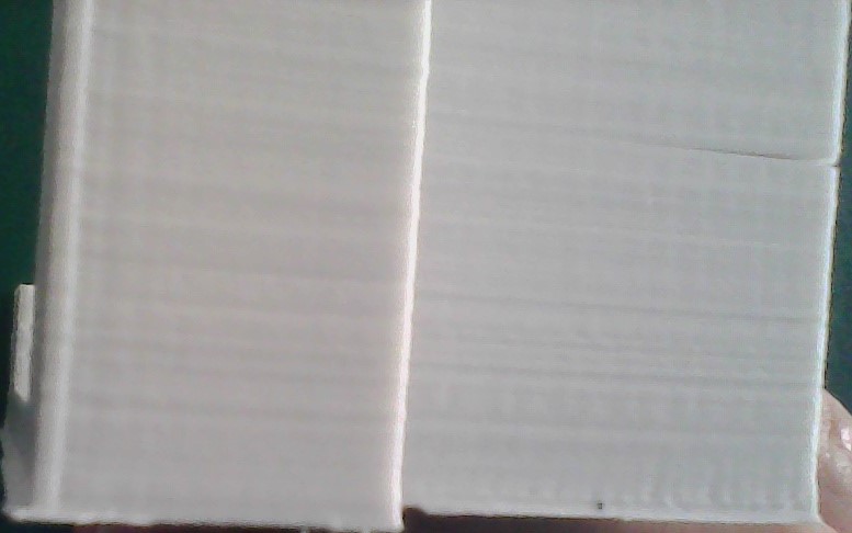
I got my Migbot about a month ago and have been printing with PLA which worked fine. I tried abs the other day and have issues with layers not sticking. The layer height is set to 0.2, Heatbed on 110 and extruder on 230. I read that i should have the fan off so for this print it was off the whole time.
Small flat parts print fine, but as soon as i try to print something with a little height the cracks form. Any help please?
Attached is a picture of the part.
|
Re: Migbot Prusa i3 Unofficial Support Thread August 07, 2015 09:32PM |
Registered: 8 years ago Posts: 18 |
in my case, i run the cooling fan for the printed layers with ABS. when i didn't, the print would go all limp and quickly separate from the glass bed. i run 230-110 btw. on another note, i've noticed talk about the migbot frame being somewhat "not rigid" and i totally agree. i can grab the y axis frame and move it side to side ..easily. all my bolts, screws and nuts are tight..very tight. i am printing good right now..tweaked and running well, but, i pulled the trigger just moments ago for a P3steel frame kit at Orballoprinting.com. i like the way its put together and i think it will be a solid base for my printer components not to mention getting a 200x200x200 print envelope. unfortunately, this place is in Spain and i don't know how long it will take for delivery. i just received an E3d hotend (chinese) and that took 3 weeks from Aliexpress. happy printing guys!
Edited 1 time(s). Last edit at 08/07/2015 09:34PM by rejaak.
Edited 1 time(s). Last edit at 08/07/2015 09:34PM by rejaak.
|
Re: Migbot Prusa i3 Unofficial Support Thread August 08, 2015 08:52AM |
Registered: 8 years ago Posts: 33 |
Quote
rejaak
in my case, i run the cooling fan for the printed layers with ABS. when i didn't, the print would go all limp and quickly separate from the glass bed. i run 230-110 btw. on another note, i've noticed talk about the migbot frame being somewhat "not rigid" and i totally agree. i can grab the y axis frame and move it side to side ..easily. all my bolts, screws and nuts are tight..very tight. i am printing good right now..tweaked and running well, but, i pulled the trigger just moments ago for a P3steel frame kit at Orballoprinting.com. i like the way its put together and i think it will be a solid base for my printer components not to mention getting a 200x200x200 print envelope. unfortunately, this place is in Spain and i don't know how long it will take for delivery. i just received an E3d hotend (chinese) and that took 3 weeks from Aliexpress. happy printing guys!
I have the Orballo frame, but haven't built it yet as it's not just a straight swap over of parts from the migbot.
The Z axis rods, which are offset on the Migbot, are in-line on the Orballo. These Orballo printed parts are the printed parts I used. I wanted to retain the leadscrews rather than going with their threaded rod. And this one for the Y axis belt Y belt clamp
|
Re: Migbot Prusa i3 Unofficial Support Thread August 08, 2015 04:18PM |
Registered: 8 years ago Posts: 18 |
i was wondering about the differences . and i just printed new right and left x mounts in abs too. drat! what about the y axis pulley? pictures show it as larger than what is on the migbot. i planned to design a tensioner for this.are the x axis smooth rods the same distance from each other so i can use the same print carriage? because i just did a redesign for one that holds my new v6 hotend and an adjustable z sensor AND printed it.
|
Re: Migbot Prusa i3 Unofficial Support Thread August 08, 2015 10:22PM |
Registered: 8 years ago Posts: 31 |
|
Re: Migbot Prusa i3 Unofficial Support Thread August 08, 2015 11:39PM |
Registered: 8 years ago Posts: 100 |
Quote
jbehan
Anyone have their acrylic Y axis carriage warp from heat while printing ABS? I did tonight, son-of-a...just found the sweet spot too. Thoughts on a replacement?
I haven't started printing with ABS yet. Was just about to. Was it a long print?
Think I remember somebody on this thread buying this one:
Amazon
but if you don't need the bearings, etc I think this one might work and its US:
Ebay
|
Re: Migbot Prusa i3 Unofficial Support Thread August 09, 2015 04:11AM |
Registered: 8 years ago Posts: 33 |
Quote
rejaak
i was wondering about the differences . and i just printed new right and left x mounts in abs too. drat! what about the y axis pulley? pictures show it as larger than what is on the migbot. i planned to design a tensioner for this.are the x axis smooth rods the same distance from each other so i can use the same print carriage? because i just did a redesign for one that holds my new v6 hotend and an adjustable z sensor AND printed it.
I printed one of the adjustable Y pulley holders. If you search thingiverse for p3steel, there are a few that show up.
The X axis parts I linked to are the same as the current migbot ones, so the x carriage should be ok. I haven't got as far as the rods yet, I'm hoping all the migbot ones are going to work ok, as the Orballo ones were a waste of money
I'm not printing in abs yet, so I'm hoping the pla parts will be durable at least for a short time. We will see once it starts printing!


Sorry, only registered users may post in this forum.