Migbot Prusa i3 Unofficial Support Thread
Posted by jcabrer
|
Re: Migbot Prusa i3 Unofficial Support Thread October 18, 2015 11:12PM |
Registered: 8 years ago Posts: 269 |
Currently in the midst of converting one of my Migbots to use a Direct Drive E3D v6 Lite. I'm trying to use as many existing parts with only a little tweaking, so I've come up with these: [www.thingiverse.com], I'm not fussed about losing about 20mm on the Z axis as I rarely print anything tall and I have a bastardised CTC to do that. Basically, both mounts (layer fan and Sensor) have been extended by 20mm which should be enough. I'll get back to you once I have them printed out.
|
Re: Migbot Prusa i3 Unofficial Support Thread October 19, 2015 12:53PM |
Registered: 8 years ago Posts: 9 |
OK, problem solved, it was a bad connection at the extruder, it just happened to work when i would move the motor, then quit working when i replaced it.
Quote
gatorNic
I suppose its possible it could be firmware, but honestly I don't think firmware just stops working unless the whole board gave out. Since it works on the x-axis we know the motor works. It's possible the E0 stepper on the board gave out (a fuse possibly, or something else). The mks board has a second extruder stepper connection for dual extruders. I would try plugging in the extruder motor to the E1 connection. Then, I believe, all you have to do is change the settings in the slicer to use the 2nd extuder. See if that works to help with the trouble shooting.
Quote
kissfan4
I have had this printer for roughly 5-6 months, and it has worked pretty well since i got it, until yesterday.
So yesterday i started a print before i left for work, when i got home i had a mess, somewhere along the print something went wrong and the print had shifted to the rear by quite a bit (20-30mm) but the print continued and finished.
I tried printing something last night, and when the print starts you can hear the extruder motor "clicking" i pulled the motor out and clicked extrude, and the motor just clicks, i plugged that motor into the wiring for the "x axis" and it worked fine.
Switched everything back to the way it should be, tried another print, it started fine, then i got a jumbled mess on the lcd display, and the motor started clicking again. i started to eliminate potential problems so i tried 2 versions of Slic3r, pronterface, and Cura. all with the same results, could this be a problem in the firmware? This issues just popped up, i have been printing without issues for 5-6 months.
. If you think it could be a firmware issue, does anyone know where i could find detailed instructions on how to upload new firmware to the printer? I have no experience with this, i do have the Arduino software, but have never really gotten to play with it.
|
Re: Migbot Prusa i3 Unofficial Support Thread October 19, 2015 11:50PM |
Registered: 9 years ago Posts: 112 |
|
Re: Migbot Prusa i3 Unofficial Support Thread October 20, 2015 05:43AM |
Registered: 8 years ago Posts: 152 |
Quote
evetanlm
Hi,
can anyone tell me how to change the code? my prusa have one issue whenever it extrude filament it restart, anyone know anythings to change the code?
Can you run Pronterface and start a print job? Then post the error lines associated with the reset. Pronterface shows all commands and replies as they occur so you should have a record of the reset.
|
Re: Migbot Prusa i3 Unofficial Support Thread October 20, 2015 02:49PM |
Registered: 8 years ago Posts: 16 |
So I just installed an automatic bed leveling sensor. Now the printer does not start printing at the midpoint anymore.
This leads the printer to go outside the printbed when printing large objects.
The printer does probe the bed at the correct corners, so th problem only seems to appear when printing and not probing.
I'm using a lj12a3-4-z/BX sensor.
Here is an exerpt from my config.h :
Edited 1 time(s). Last edit at 10/20/2015 02:49PM by kaffemustasj.
This leads the printer to go outside the printbed when printing large objects.
The printer does probe the bed at the correct corners, so th problem only seems to appear when printing and not probing.
I'm using a lj12a3-4-z/BX sensor.
Here is an exerpt from my config.h :
// Travel limits after homing
#define X_MAX_POS 200
#define X_MIN_POS -15 // 0
#define Y_MAX_POS 200
#define Y_MIN_POS -45 // 0
#define Z_MAX_POS 180
#define Z_MIN_POS 0


    // set the rectangle in which to probe
    #define LEFT_PROBE_BED_POSITION 15   //0
    #define RIGHT_PROBE_BED_POSITION 190  //180
    #define BACK_PROBE_BED_POSITION 190   //120
    #define FRONT_PROBE_BED_POSITION 15  //-40
Edited 1 time(s). Last edit at 10/20/2015 02:49PM by kaffemustasj.
|
Re: Migbot Prusa i3 Unofficial Support Thread October 20, 2015 02:56PM |
Registered: 8 years ago Posts: 269 |
Quote
kaffemustasj
So I just installed an automatic bed leveling sensor. Now the printer does not start printing at the midpoint anymore.
This leads the printer to go outside the printbed when printing large objects.
The printer does probe the bed at the correct corners, so th problem only seems to appear when printing and not probing.
I'm using a lj12a3-4-z/BX sensor.
Here is an exerpt from my config.h :
// Travel limits after homing
#define X_MAX_POS 200
#define X_MIN_POS -15 // 0
#define Y_MAX_POS 200
#define Y_MIN_POS -45 // 0
#define Z_MAX_POS 180
#define Z_MIN_POS 0


    // set the rectangle in which to probe
    #define LEFT_PROBE_BED_POSITION 15   //0
    #define RIGHT_PROBE_BED_POSITION 190  //180
    #define BACK_PROBE_BED_POSITION 190   //120
    #define FRONT_PROBE_BED_POSITION 15  //-40
Check your probe offsets. I know with one of mine (I've not set the other up yet to auto level) that the firmware settings and the actual offsets are completely different. You want to be looking at this:
  #define X_PROBE_OFFSET_FROM_EXTRUDER 12
  #define Y_PROBE_OFFSET_FROM_EXTRUDER 60
  #define Z_PROBE_OFFSET_FROM_EXTRUDER -0.8
Specifically the X and Y to get it to print in the centre, you'll probably need to fiddle with it to get it centred. The actual values and the ones that are in my firmware are totally different. The above, by the way, is from the base Migbot firmware.
Edited 2 time(s). Last edit at 10/20/2015 03:00PM by Ax.
|
Re: Migbot Prusa i3 Unofficial Support Thread October 20, 2015 03:23PM |
Registered: 8 years ago Posts: 16 |
|
Re: Migbot Prusa i3 Unofficial Support Thread October 20, 2015 03:28PM |
Registered: 8 years ago Posts: 9 |
i am somewhat of a newbie still to 3d printing so i have to ask, when you guys are talking about your config file, how are you accessing it? I have the Arduino IDE but how do you find out what your settings are on your printer? When my printer is hooked up, and i open Arduino, i select the board, but have no idea how to see what the settings are. I would like to be able to edit them, because like many, my printer does not print in the center of the bed. Any help would be greatly appreciated.
|
Re: Migbot Prusa i3 Unofficial Support Thread October 20, 2015 03:28PM |
Registered: 8 years ago Posts: 269 |
Quote
kaffemustasj
Thanks. I had no idea that the offsets where the values I had to fiddle around with.
No worries, Tom's Guide for this is pretty much a go to for this - [www.youtube.com]
|
Re: Migbot Prusa i3 Unofficial Support Thread October 20, 2015 03:32PM |
Registered: 8 years ago Posts: 269 |
Quote
kissfan4
i am somewhat of a newbie still to 3d printing so i have to ask, when you guys are talking about your config file, how are you accessing it? I have the Arduino IDE but how do you find out what your settings are on your printer? When my printer is hooked up, and i open Arduino, i select the board, but have no idea how to see what the settings are. I would like to be able to edit them, because like many, my printer does not print in the center of the bed. Any help would be greatly appreciated.
You need to have the firmware files. Arduino IDE is just a program to edit the actual firmware files and upload it. I've just bought another recently and the firmware and all the files needed for setup are now on github here
Edited 1 time(s). Last edit at 10/20/2015 03:36PM by Ax.
|
Re: Migbot Prusa i3 Unofficial Support Thread October 21, 2015 09:28PM |
Registered: 9 years ago Posts: 1 |
Hi guys,
a friend purchased 3 weeks ago a MigBot Prusa i3 (not from 3dprintersonline.com). He is a newbie and ecnountered several issues. I helped him, re-flashing Marlin on the MKS Base v1.2 ( I used as template the file posted in the first page of this thread, and I only edited the X and Y soft endstops, and commented the Auto Bed Levelling because there isn't a probe yet).
Now the printer works fine but he told me that if he tries to change the bed temperature during printing, the display flashes (and maybe appears something) and then he must reboot. He couldn't provide me further explanations (he's a 100% beginner).
I can't understand what's happening.
Also, the bed needs up to half an hour to get hot (room temp about 25°C, target temp about 100°C.....).
However I will read all the 11 pages of this thread if there's something.
|
Re: Migbot Prusa i3 Unofficial Support Thread October 21, 2015 09:34PM |
Registered: 9 years ago Posts: 112 |
|
Re: Migbot Prusa i3 Unofficial Support Thread October 21, 2015 09:34PM |
Registered: 9 years ago Posts: 112 |
|
Re: Migbot Prusa i3 Unofficial Support Thread October 23, 2015 02:35AM |
Registered: 8 years ago Posts: 8 |
Is there a way to connect the extruder fan to the board so that I can control it according to the hotend temperature?
I hate turning the printer off all the time, and the constantly running extruder fan bothers me even more, since the printer sits next to my computer.
I was thinking of adding a timer switch to it and connect the fan to the hotend heater: The fan would start when the hotend gets power, and continue to run a few minutes after the heater turns off. Then I figured, that it would be better if the extruder fan could use the thermistor information as a sort of thermostat - the fan runs if the hotend temp is higher than lets say 40 degrees and stops when it's lower than that.
|
Re: Migbot Prusa i3 Unofficial Support Thread October 23, 2015 03:23AM |
Registered: 8 years ago Posts: 269 |
Quote
cmaet
Is there a way to connect the extruder fan to the board so that I can control it according to the hotend temperature?
I hate turning the printer off all the time, and the constantly running extruder fan bothers me even more, since the printer sits next to my computer.
I was thinking of adding a timer switch to it and connect the fan to the hotend heater: The fan would start when the hotend gets power, and continue to run a few minutes after the heater turns off. Then I figured, that it would be better if the extruder fan could use the thermistor information as a sort of thermostat - the fan runs if the hotend temp is higher than lets say 40 degrees and stops when it's lower than that.
There's a header on the board for the layer fan, labelled fan. You could in theory, hook the cooling fan up to this as well, but you'd need to have them both on from the start of the print.
|
Re: Migbot Prusa i3 Unofficial Support Thread October 23, 2015 08:10PM |
Registered: 8 years ago Posts: 111 |
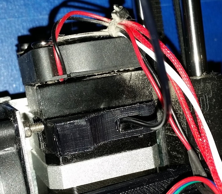
Printed out my modified filament feeder. Loading filament is SO much easier now, even towards the bottom of the spool where the winding is really tight. I reinforced the area around the bearing with some epoxy, just for added strength. Printed at 75% infill.
What do you think?
What do you think?
|
Re: Migbot Prusa i3 Unofficial Support Thread October 24, 2015 08:07AM |
Registered: 8 years ago Posts: 16 |
So I've just installed and calibrated a auto leveling sensor, however I'm getting some strange behavior.
When I print from the SD card, and the printer runs through the G29 command the Z axis only rises, without lowering.
This means the Z axis never triggers, and it gets higher and higher every time it tries to probe or home.
What can I do about this?
When I print from the SD card, and the printer runs through the G29 command the Z axis only rises, without lowering.
This means the Z axis never triggers, and it gets higher and higher every time it tries to probe or home.
What can I do about this?
|
Re: Migbot Prusa i3 Unofficial Support Thread October 25, 2015 05:53AM |
Registered: 8 years ago Posts: 152 |
Quote
kaffemustasj
So I've just installed and calibrated a auto leveling sensor, however I'm getting some strange behavior.
When I print from the SD card, and the printer runs through the G29 command the Z axis only rises, without lowering.
This means the Z axis never triggers, and it gets higher and higher every time it tries to probe or home.
What can I do about this?
From Pronterface, Repeiter, etc issue the M119 command. The printer will tell you the status of each endstop. This will give you troubleshooting information. My first thought is that the Z-Min is triggered. Marlin firmware (by default) raises the head 5mm before each probe so it keeps going up and up each time you issue the G29 command.
|
Re: Migbot Prusa i3 Unofficial Support Thread October 25, 2015 10:32AM |
Registered: 8 years ago Posts: 16 |
Quote
gwc2795
Quote
kaffemustasj
So I've just installed and calibrated a auto leveling sensor, however I'm getting some strange behavior.
When I print from the SD card, and the printer runs through the G29 command the Z axis only rises, without lowering.
This means the Z axis never triggers, and it gets higher and higher every time it tries to probe or home.
What can I do about this?
From Pronterface, Repeiter, etc issue the M119 command. The printer will tell you the status of each endstop. This will give you troubleshooting information. My first thought is that the Z-Min is triggered. Marlin firmware (by default) raises the head 5mm before each probe so it keeps going up and up each time you issue the G29 command.
Thanks man. The probe has a LED which lights up when it's triggered, and the LED does not show as triggered at some corners of the bed when probing.
Could this issue come because I'm stepping down the voltage with a LM7805 instead of using resistors in a voltage divider?
|
Re: Migbot Prusa i3 Unofficial Support Thread October 25, 2015 10:59AM |
Registered: 8 years ago Posts: 269 |
Quote
kaffemustasj
Quote
gwc2795
Quote
kaffemustasj
So I've just installed and calibrated a auto leveling sensor, however I'm getting some strange behavior.
When I print from the SD card, and the printer runs through the G29 command the Z axis only rises, without lowering.
This means the Z axis never triggers, and it gets higher and higher every time it tries to probe or home.
What can I do about this?
From Pronterface, Repeiter, etc issue the M119 command. The printer will tell you the status of each endstop. This will give you troubleshooting information. My first thought is that the Z-Min is triggered. Marlin firmware (by default) raises the head 5mm before each probe so it keeps going up and up each time you issue the G29 command.
Thanks man. The probe has a LED which lights up when it's triggered, and the LED does not show as triggered at some corners of the bed when probing.
Could this issue come because I'm stepping down the voltage with a LM7805 instead of using resistors in a voltage divider?
I had a similar issue with the stock Sensor on my first Migbot. The back right corner of the bed just wouldn't seem to trigger properly, and it just ended crashing the sensor into the bed. I had some copper tape lying around and stuck that to it as a test, triggered every time. I'm now on glass with sensor points made out of the same copper tape. Works a charm on both my Migbots, I'm actually almost at 4mm sensing distance due to this too. May be worth finding something metal, thin with a decent iron content and sticking it to the bed to see what happens.
In my limited understanding a Step-Down board would not fluctuate much below 5v. You should be able to test that with a Multimeter.
|
Re: Migbot Prusa i3 Unofficial Support Thread October 25, 2015 11:16AM |
Registered: 8 years ago Posts: 16 |
Quote
Ax
Quote
kaffemustasj
Quote
gwc2795
Quote
kaffemustasj
So I've just installed and calibrated a auto leveling sensor, however I'm getting some strange behavior.
When I print from the SD card, and the printer runs through the G29 command the Z axis only rises, without lowering.
This means the Z axis never triggers, and it gets higher and higher every time it tries to probe or home.
What can I do about this?
From Pronterface, Repeiter, etc issue the M119 command. The printer will tell you the status of each endstop. This will give you troubleshooting information. My first thought is that the Z-Min is triggered. Marlin firmware (by default) raises the head 5mm before each probe so it keeps going up and up each time you issue the G29 command.
Thanks man. The probe has a LED which lights up when it's triggered, and the LED does not show as triggered at some corners of the bed when probing.
Could this issue come because I'm stepping down the voltage with a LM7805 instead of using resistors in a voltage divider?
I had a similar issue with the stock Sensor on my first Migbot. The back right corner of the bed just wouldn't seem to trigger properly, and it just ended crashing the sensor into the bed. I had some copper tape lying around and stuck that to it as a test, triggered every time. I'm now on glass with sensor points made out of the same copper tape. Works a charm on both my Migbots, I'm actually almost at 4mm sensing distance due to this too. May be worth finding something metal, thin with a decent iron content and sticking it to the bed to see what happens.
In my limited understanding a Step-Down board would not fluctuate much below 5v. You should be able to test that with a Multimeter.
I'll look for something metal I can use. I'm currently using the aluminum print bed, so I didn't think there should be any problem with that.
Yea, the voltage shouldn't drop below 5V. I'm wondering if that might be a problem?
Do you know if the sensor is supposed to give off an on/off signal, or a variable signal which varies with the height of the probe?
|
Re: Migbot Prusa i3 Unofficial Support Thread October 25, 2015 11:19AM |
Registered: 8 years ago Posts: 152 |
Quote
kaffemustasj
Quote
gwc2795
Quote
kaffemustasj
So I've just installed and calibrated a auto leveling sensor, however I'm getting some strange behavior.
When I print from the SD card, and the printer runs through the G29 command the Z axis only rises, without lowering.
This means the Z axis never triggers, and it gets higher and higher every time it tries to probe or home.
What can I do about this?
From Pronterface, Repeiter, etc issue the M119 command. The printer will tell you the status of each endstop. This will give you troubleshooting information. My first thought is that the Z-Min is triggered. Marlin firmware (by default) raises the head 5mm before each probe so it keeps going up and up each time you issue the G29 command.
Thanks man. The probe has a LED which lights up when it's triggered, and the LED does not show as triggered at some corners of the bed when probing.
Could this issue come because I'm stepping down the voltage with a LM7805 instead of using resistors in a voltage divider?
I used a voltage divider on mine and had a similar problem until I could sink the voltage on the Z- min pin. I would suggest that you change the firmware to not place 5V on the Z- MIN pin. That way your 5V source would dependably trigger it. I ended up having to use 680 ohm and 1K ohm resistors in the voltage divider to get mine working. I am not sure what to google to find the change you need to make in Marlin. You have an all metal bed so you will not need the tape. Also if your Z axis has missed steps and is not level with the Y axis rods you can have problems.
Edited 1 time(s). Last edit at 10/25/2015 11:23AM by gwc2795.
|
Re: Migbot Prusa i3 Unofficial Support Thread October 25, 2015 11:29AM |
Registered: 8 years ago Posts: 269 |
Quote
kaffemustasj
Yea, the voltage shouldn't drop below 5V. I'm wondering if that might be a problem?
Do you know if the sensor is supposed to give off an on/off signal, or a variable signal which varies with the height of the probe?
Not sure if it's on/off or variable. If it's triggering reliably with something metal held to it, and the firmware is detecting it, it can only leave the bed. Remember these sensors are designed to sense Iron, hence having to lower the sensor from 4mm to 2mm. If the composition of the Aluminium bed is not uniform, then this could cause the issues you're seeing. Having 2 of these, both with the stock sensors (no voltage dividers needed, 2nd was bought without and then added to later), the beds aren't overly high quality, hence me using glass and Copper Tape to level on.
|
Re: Migbot Prusa i3 Unofficial Support Thread October 25, 2015 12:45PM |
Registered: 8 years ago Posts: 16 |
So I measured the voltage coming of the voltage regulator and it was 2.33V, this was no good, so I changed it out with a voltage divider. The sensor now reads 3.2V.
However, how I've ran into another problem.
When I try to home the Z axis, the sensor lights up and triggers, but the Z axis keeps on lowering. This means the sensor and printhead slams into the printbed and keeps on trying to lower.
So I've tested with M119. The problem is that the sensor is always open, it never shows as triggered. This is although the voltage drops from 3.3V to 0 when a metal object is placed under the probe.
Edited 1 time(s). Last edit at 10/25/2015 01:55PM by kaffemustasj.
|
Re: Migbot Prusa i3 Unofficial Support Thread October 25, 2015 03:09PM |
Registered: 8 years ago Posts: 269 |
|
Re: Migbot Prusa i3 Unofficial Support Thread October 25, 2015 03:43PM |
Registered: 8 years ago Posts: 152 |
Quote
kaffemustasj
So I measured the voltage coming of the voltage regulator and it was 2.33V, this was no good, so I changed it out with a voltage divider. The sensor now reads 3.2V.
However, how I've ran into another problem.
When I try to home the Z axis, the sensor lights up and triggers, but the Z axis keeps on lowering. This means the sensor and printhead slams into the printbed and keeps on trying to lower.
So I've tested with M119. The problem is that the sensor is always open, it never shows as triggered. This is although the voltage drops from 3.3V to 0 when a metal object is placed under the probe.
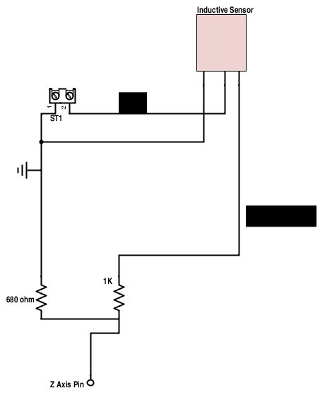
I had the exact problem when I added the sensor to my Migbot. I disconnected the sensor from the pin and measured the pin voltage on the pin the sensor connects to and found it was supplying 5V. I tested various resistance values to find one that took the pin voltage to <0.2V when I connected it to ground. In my case that value was 680 ohm. I used that as the resistor that connects to the pin and ground in the voltage divider. A 1K resistor allows the voltage to rise to ~4V from the output of the sensor. The sensor I have is normally closed and opens when the bed is sensed. Before the changes to the voltage divider resistance values mine tried to go through the bed.
|
Re: Migbot Prusa i3 Unofficial Support Thread October 25, 2015 05:27PM |
Registered: 8 years ago Posts: 16 |
Quote
gwc2795
Quote
kaffemustasj
So I measured the voltage coming of the voltage regulator and it was 2.33V, this was no good, so I changed it out with a voltage divider. The sensor now reads 3.2V.
However, how I've ran into another problem.
When I try to home the Z axis, the sensor lights up and triggers, but the Z axis keeps on lowering. This means the sensor and printhead slams into the printbed and keeps on trying to lower.
So I've tested with M119. The problem is that the sensor is always open, it never shows as triggered. This is although the voltage drops from 3.3V to 0 when a metal object is placed under the probe.
I had the exact problem when I added the sensor to my Migbot. I disconnected the sensor from the pin and measured the pin voltage on the pin the sensor connects to and found it was supplying 5V. I tested various resistance values to find one that took the pin voltage to <0.2V when I connected it to ground. In my case that value was 680 ohm. I used that as the resistor that connects to the pin and ground in the voltage divider. A 1K resistor allows the voltage to rise to ~4V from the output of the sensor. The sensor I have is normally closed and opens when the bed is sensed. Before the changes to the voltage divider resistance values mine tried to go through the bed.
Yeah, I'm guessing that's my problem. I measured 5V coming from the motherboard pins without the sensor connected.
When the sensor is connected to the board I'm reading 4.7V with a drop to 2.3V when the probe is triggered.
I've used a 15k ohm and a 10k ohm resistor in the voltage divider.
Could you draw your circuit in paint or whatever, so I'm sure I understand how to duplicate your connections?
|
Re: Migbot Prusa i3 Unofficial Support Thread October 25, 2015 08:21PM |
Registered: 8 years ago Posts: 152 |
Quote
kaffemustasj
Quote
gwc2795
Quote
kaffemustasj
So I measured the voltage coming of the voltage regulator and it was 2.33V, this was no good, so I changed it out with a voltage divider. The sensor now reads 3.2V.
However, how I've ran into another problem.
When I try to home the Z axis, the sensor lights up and triggers, but the Z axis keeps on lowering. This means the sensor and printhead slams into the printbed and keeps on trying to lower.
So I've tested with M119. The problem is that the sensor is always open, it never shows as triggered. This is although the voltage drops from 3.3V to 0 when a metal object is placed under the probe.
I had the exact problem when I added the sensor to my Migbot. I disconnected the sensor from the pin and measured the pin voltage on the pin the sensor connects to and found it was supplying 5V. I tested various resistance values to find one that took the pin voltage to <0.2V when I connected it to ground. In my case that value was 680 ohm. I used that as the resistor that connects to the pin and ground in the voltage divider. A 1K resistor allows the voltage to rise to ~4V from the output of the sensor. The sensor I have is normally closed and opens when the bed is sensed. Before the changes to the voltage divider resistance values mine tried to go through the bed.
Yeah, I'm guessing that's my problem. I measured 5V coming from the motherboard pins without the sensor connected.
When the sensor is connected to the board I'm reading 4.7V with a drop to 2.3V when the probe is triggered.
I've used a 15k ohm and a 10k ohm resistor in the voltage divider.
Could you draw your circuit in paint or whatever, so I'm sure I understand how to duplicate your connections?
Best I can draw. Hope it helps
|
Re: Migbot Prusa i3 Unofficial Support Thread October 25, 2015 11:47PM |
Registered: 8 years ago Posts: 34 |
I'm having an issue as well with my Auto leveling in almost the same way as above, I have my sensor hooked to 12V and a V divider so the signal wire outputs about 4.5V, it is Normally closed so outputs 4.5V when NOT triggered. I have the endstop inverted in the firmware pullup disabled and all that. My issue is that when hooked up does nothing triggered or not it always reads as open. Power is hooked direct to 12V and Negative is direct to ground, 4.5V signal is hooked to the pin on the board that is not outputting 5V, hooked back up old endstop and everything is working fine there so it is something to do with the proximity sensor. Please help.
Oh for reference this is my sensor [www.amazon.com]
Oh for reference this is my sensor [www.amazon.com]
|
Re: Migbot Prusa i3 Unofficial Support Thread October 26, 2015 06:00AM |
Registered: 8 years ago Posts: 152 |
Quote
CrackinX
I'm having an issue as well with my Auto leveling in almost the same way as above, I have my sensor hooked to 12V and a V divider so the signal wire outputs about 4.5V, it is Normally closed so outputs 4.5V when NOT triggered. I have the endstop inverted in the firmware pullup disabled and all that. My issue is that when hooked up does nothing triggered or not it always reads as open. Power is hooked direct to 12V and Negative is direct to ground, 4.5V signal is hooked to the pin on the board that is not outputting 5V, hooked back up old endstop and everything is working fine there so it is something to do with the proximity sensor. Please help.
Oh for reference this is my sensor [www.amazon.com]
Measure the voltage from the shell of the USB connector and the output of the sensor when you trigger the sensor. The voltage is going to read about 12V if the sensor is working.


Sorry, only registered users may post in this forum.