Migbot Prusa i3 Unofficial Support Thread
Posted by jcabrer
|
Re: Migbot Prusa i3 Unofficial Support Thread November 08, 2015 08:26PM |
Registered: 8 years ago Posts: 152 |
Quote
veaceonee
Quick question,
What do you guys do to prevents the bearings from coming out of the X-carriage during a print? mine slide out when it is moving.
I printed bearing holders for both the X and Z axis.
Use Migbot Bearing Retainer X-axis Top.stl and Migbot Bearing Retainer X-axis Bottom.stl if you have a brace on the top of the extruder, otherwise use 2 of the Migbot Bearing Retainer X-axis Bottom.stl.
The bearing retainers are lightweight and therefore can be fragile. When you clean out the built in support bars, make sure you get the support structures cleaned out, or they will be too tight when clipped onto the smooth rods. Take a sharp knife, etc to make sure the braces slide easily when pressed onto the smooth rods, so as not to offer resistance to the stepper motors.
Print without support.
|
Re: Migbot Prusa i3 Unofficial Support Thread November 08, 2015 09:28PM |
Registered: 8 years ago Posts: 111 |
|
Re: Migbot Prusa i3 Unofficial Support Thread November 09, 2015 06:45PM |
Registered: 8 years ago Posts: 34 |
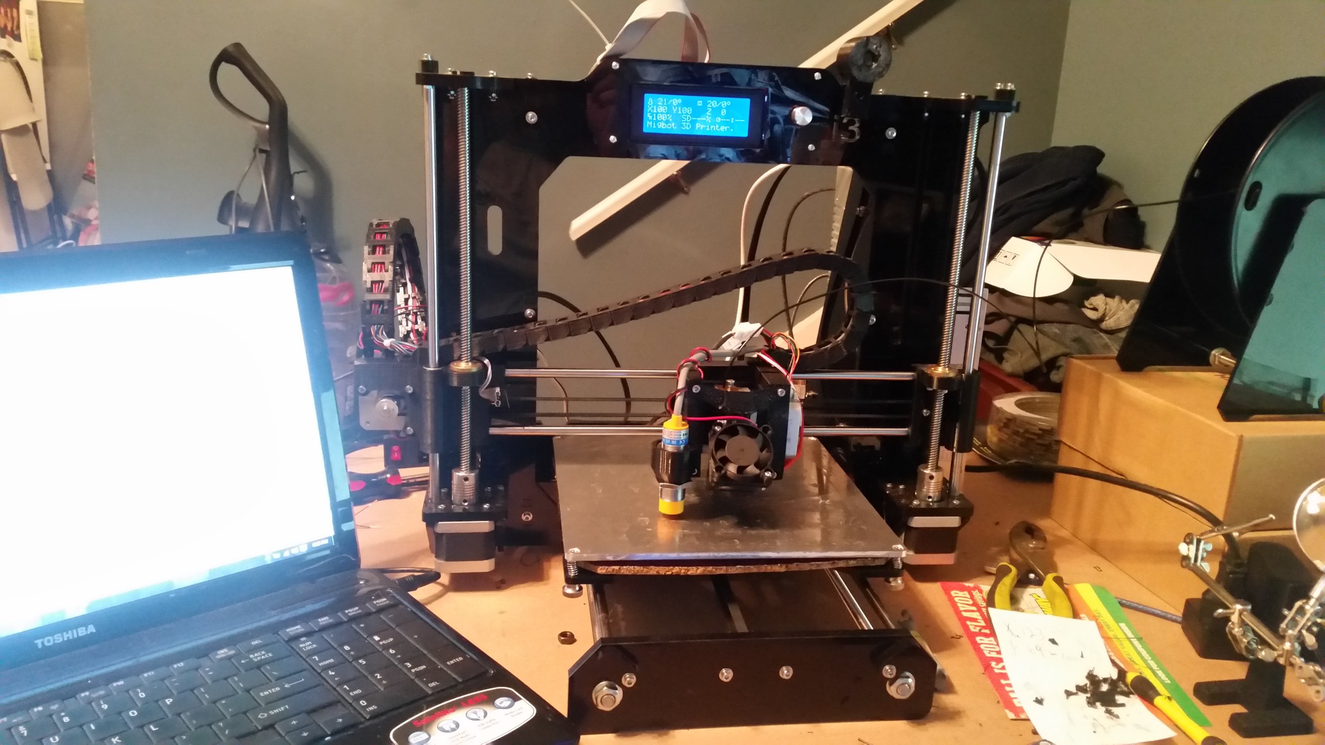
Well here is my Migbot rework thus far, still a few more items to make to get the rats nest of wires sorted out but I have included all the STL files I have made/reworked for it.
[drive.google.com]
there are 28 wire chain bits on the x axis, 17 on the Z.
Also I think I'm going to try and make the 18MM bed sensor mount a bit shorter as it is too far away from the nozzle to get a 16 point auto level.
Most of these I can not take credit for as they came from Thingverse and are re-works to fit the migbot.
Any questions please feel free to ask
Edited 1 time(s). Last edit at 11/09/2015 07:25PM by CrackinX.
|
Re: Migbot Prusa i3 Unofficial Support Thread November 09, 2015 07:06PM |
Registered: 8 years ago Posts: 100 |
Quote
CrackinX
Also I think I'm going to try and make the 18MM bed sensor mount a bit as it is too far away from the nozzle to get a 16 point auto level.
Any questions please feel free to ask
The only reason to do a 16 point autolevel is if you have a warped metal bed. I had one, it was painful. Even 16 point wasn't working all that well. Save yourself the agony and get a quality glass plate and just do a 4 point. The flatness of the glass with save you pain and a 4 point level is way faster. Only downside is you either need a different sensor that can sense greater than 4mm so it can go through glass, or what I did with the default sensor was just put 4 little corners of aluminum foil.
Its so easy to print on the glass with ABS. Just put some purple elmers glue down, super easy no adhesion issues. PLA you can still continue to use painters tape, but I should actually try PLA with the glue as well.
Also ofcourse added the adjustable sensor bracket with is a huge timesaver to get minute changes.
Edited 2 time(s). Last edit at 11/09/2015 07:08PM by gatorNic.
|
Re: Migbot Prusa i3 Unofficial Support Thread November 09, 2015 07:20PM |
Registered: 8 years ago Posts: 34 |
Quote
gatorNic
Quote
CrackinX
Also I think I'm going to try and make the 18MM bed sensor mount a bit as it is too far away from the nozzle to get a 16 point auto level.
Any questions please feel free to ask
The only reason to do a 16 point autolevel is if you have a warped metal bed. I had one, it was painful. Even 16 point wasn't working all that well. Save yourself the agony and get a quality glass plate and just do a 4 point. The flatness of the glass with save you pain and a 4 point level is way faster. Only downside is you either need a different sensor that can sense greater than 4mm so it can go through glass, or what I did with the default sensor was just put 4 little corners of aluminum foil.
Its so easy to print on the glass with ABS. Just put some purple elmers glue down, super easy no adhesion issues. PLA you can still continue to use painters tape, but I should actually try PLA with the glue as well.
Also ofcourse added the adjustable sensor bracket with is a huge timesaver to get minute changes.
The sensor I have is an 8MM type, I have a glass plate but I'm not sure if the sensor will detect the aluminum even through the 3mm glass, I'm thinking of picking up some sheet metal as an underlayment, which should sense just fine. My plate is not THAT warped so I have been getting along ok with a 9 point autolevel.
|
Re: Migbot Prusa i3 Unofficial Support Thread November 09, 2015 07:50PM |
Registered: 8 years ago Posts: 100 |
Quote
CrackinX
The sensor I have is an 8MM type, I have a glass plate but I'm not sure if the sensor will detect the aluminum even through the 3mm glass, I'm thinking of picking up some sheet metal as an underlayment, which should sense just fine. My plate is not THAT warped so I have been getting along ok with a 9 point autolevel.
Well then I think 16point would be a bit overkill.
Yeah you really would need something that could conform to the glass plate. Because say you have a warped plate under the glass, it would still have the same problems no matter how flat the glass. So yeah maybe some sheet metal would work or even just a whole sheet of aluminum foil attached tightly on the underside. It doesn't take much for the sensor.
|
Re: Migbot Prusa i3 Unofficial Support Thread November 10, 2015 11:55AM |
Registered: 8 years ago Posts: 34 |
Quote
gatorNic
Quote
CrackinX
The sensor I have is an 8MM type, I have a glass plate but I'm not sure if the sensor will detect the aluminum even through the 3mm glass, I'm thinking of picking up some sheet metal as an underlayment, which should sense just fine. My plate is not THAT warped so I have been getting along ok with a 9 point autolevel.
Well then I think 16point would be a bit overkill.
Yeah you really would need something that could conform to the glass plate. Because say you have a warped plate under the glass, it would still have the same problems no matter how flat the glass. So yeah maybe some sheet metal would work or even just a whole sheet of aluminum foil attached tightly on the underside. It doesn't take much for the sensor.
I actually just broke down and ordered an mk3 bed I'm going to swap over to the 3 point leveling, run the 12v line off a dedicated 24v supply with an ssr, and put the glass on top. The new bed being an integrated aluminum plate will solve the sensor issue as well.
|
Re: Migbot Prusa i3 Unofficial Support Thread November 10, 2015 12:23PM |
Registered: 8 years ago Posts: 100 |
Quote
CrackinX
I actually just broke down and ordered an mk3 bed I'm going to swap over to the 3 point leveling, run the 12v line off a dedicated 24v supply with an ssr, and put the glass on top. The new bed being an integrated aluminum plate will solve the sensor issue as well.
cool. good luck!
|
Re: Migbot Prusa i3 Unofficial Support Thread November 10, 2015 04:18PM |
Registered: 8 years ago Posts: 269 |
OK, so I've finally got around to desiging a proper mount for the E3D Lite6s (will also work for the v6) I run on my Migbots - [www.thingiverse.com]
There's 3 iterations, one was a screw up as I designed around a smaller stepper motor, but may come in handy, the 2nd was designed around the correct size motor, but I soon discovered that it was no good for the large bed as you lose about 30mm on the back of the bed with the motor facing out, however it may work with the standard bed, and the final version which is on both my Migbots which is a side on mount. I may go for one last iteration as I can't get the firmware to go totally central with the firmware, it's off to the right, so I'll probably shunt it over a little. I've also included my very extended sensor mount, which needs a little work as it needs toughening up due to the extended length and can break easily (from experience) if it catches anything on the bed. It's all designed to drop in and bolt on using the existing Y Axis and extruder assembly.
Anyways, Enjoy.
|
Re: Migbot Prusa i3 Unofficial Support Thread November 11, 2015 09:49PM |
Registered: 8 years ago Posts: 34 |
Quote
gatorNic
Quote
CrackinX
I actually just broke down and ordered an mk3 bed I'm going to swap over to the 3 point leveling, run the 12v line off a dedicated 24v supply with an ssr, and put the glass on top. The new bed being an integrated aluminum plate will solve the sensor issue as well.
cool. good luck!
Well Epic fail on the SSR, MK3 bed heated up in about 2 minutes to 100 and then just kept going all the way to thermal limit in about 4 minutes. The SSR failed open almost immediately, guess I'll be sending that back to amazon...
|
Re: Migbot Prusa i3 Unofficial Support Thread November 12, 2015 05:28AM |
Registered: 8 years ago Posts: 152 |
Quote
CrackinX
Quote
gatorNic
Quote
CrackinX
I actually just broke down and ordered an mk3 bed I'm going to swap over to the 3 point leveling, run the 12v line off a dedicated 24v supply with an ssr, and put the glass on top. The new bed being an integrated aluminum plate will solve the sensor issue as well.
cool. good luck!
Well Epic fail on the SSR, MK3 bed heated up in about 2 minutes to 100 and then just kept going all the way to thermal limit in about 4 minutes. The SSR failed open almost immediately, guess I'll be sending that back to amazon...
What was the model number of the SSR?
You need an SSR that ends in DD to control DC current, example SSR-25DD will control the heated bed or extruder. SSR-??AA or SSR-??DA will not work. The SSR-??DA would do exactly what you describe The DA series uses a triac to switch the device on/off and it can only switch off when the voltage reaches zero (with AC). The DD uses a FET and can turn the current on/off without it being at zero.
Make sure you get a SSR-??DD.
Edited 1 time(s). Last edit at 11/12/2015 05:29AM by gwc2795.
|
Re: Migbot Prusa i3 Unofficial Support Thread November 12, 2015 06:22AM |
Registered: 8 years ago Posts: 111 |
|
Re: Migbot Prusa i3 Unofficial Support Thread November 12, 2015 07:34AM |
Registered: 8 years ago Posts: 34 |
Quote
gwc2795
Quote
CrackinX
Quote
gatorNic
Quote
CrackinX
I actually just broke down and ordered an mk3 bed I'm going to swap over to the 3 point leveling, run the 12v line off a dedicated 24v supply with an ssr, and put the glass on top. The new bed being an integrated aluminum plate will solve the sensor issue as well.
cool. good luck!
Well Epic fail on the SSR, MK3 bed heated up in about 2 minutes to 100 and then just kept going all the way to thermal limit in about 4 minutes. The SSR failed open almost immediately, guess I'll be sending that back to amazon...
What was the model number of the SSR?
You need an SSR that ends in DD to control DC current, example SSR-25DD will control the heated bed or extruder. SSR-??AA or SSR-??DA will not work. The SSR-??DA would do exactly what you describe The DA series uses a triac to switch the device on/off and it can only switch off when the voltage reaches zero (with AC). The DD uses a FET and can turn the current on/off without it being at zero.
Make sure you get a SSR-??DD.
[www.amazon.com]
That's the one, has a DD at the end. I ordered a replacement and I think this time I'm going to work out some active cooling.
|
Re: Migbot Prusa i3 Unofficial Support Thread November 12, 2015 12:57PM |
Registered: 8 years ago Posts: 14 |
Hi Everyone !!!
I am brandnew to this Forum - and a brandnew owner of the same printer ;-) Read yesterday the whole 26 pages and found a lot and usefull information !
Let me indrodue:
Bought via EBay one of these - my first 3D printer - from China TL Maker or something. Nice contact to the guy from EBay and nice contact to the seller in China. TILL - ich gave a positive evaluation on EBay for the seller and the product - since then - nothing - no respond do emails, questions what so ever :-/
While the buying process - email came back fast as lighning - now - nothing. Thats proabably the lacking "support" what was mentionend so often.
Anyway - the printer - I thought it would be much worse as for a chines product, but I must say - nice tolerances, everything there , all parts OK and working. Even the printed parts are not toooooo bad.
To make a long story shorter: Its assembled and the first test print after "calibraing" (what I could find for doing so) was horrible - no big deal - Ill get into that. Heatbed upgrade I guess, proper settings, heats, adhesion, etc - Ill get to that step by step.
But - Guys - my main question for my start is about Firmware. The vendor couldn supply his orginial - what I think is anyway just basic - the Menue of the printer itsself is very limitied. I read a bit about Marlin and found also here in this post a few who thankfully supply them. Very good. Started to read and tweak a few things - working on a Mac - installed the FTDI driver for Arduiono and also uploaded it.
I think it took the values I tweaked - but dindt "upgrade" the Menue for the LCD.
In the one Firmware - there was a PDF for the LCD Tree Menue structure - but after flashing the firmawar - Menue looks the same.
Did I miss something in the firmware file to activate ?
Missing also a basic "leveling" in the menue - not to mention the often talked about Auto-Bed-Level with the sensor - which I also have ;-) Didnt try yet to get this topic going - will take it step by step.
So anyone helfpfull hints how to properly flash the firmware (Marlin) with a Mac ?
Im very thankfull that I found this forum and thread and maybe hopefully can also contribute something sometimes
So long - Cheers - and a nice welcome
Marty
|
Re: Migbot Prusa i3 Unofficial Support Thread November 12, 2015 04:36PM |
Registered: 8 years ago Posts: 152 |
|
Re: Migbot Prusa i3 Unofficial Support Thread November 12, 2015 04:40PM |
Registered: 8 years ago Posts: 269 |
Quote
Marty77
Hi Everyone !!!
I am brandnew to this Forum - and a brandnew owner of the same printer ;-) Read yesterday the whole 26 pages and found a lot and usefull information !
Let me indrodue:
Bought via EBay one of these - my first 3D printer - from China TL Maker or something. Nice contact to the guy from EBay and nice contact to the seller in China. TILL - ich gave a positive evaluation on EBay for the seller and the product - since then - nothing - no respond do emails, questions what so ever :-/
While the buying process - email came back fast as lighning - now - nothing. Thats proabably the lacking "support" what was mentionend so often.
Anyway - the printer - I thought it would be much worse as for a chines product, but I must say - nice tolerances, everything there , all parts OK and working. Even the printed parts are not toooooo bad.
To make a long story shorter: Its assembled and the first test print after "calibraing" (what I could find for doing so) was horrible - no big deal - Ill get into that. Heatbed upgrade I guess, proper settings, heats, adhesion, etc - Ill get to that step by step.
But - Guys - my main question for my start is about Firmware. The vendor couldn supply his orginial - what I think is anyway just basic - the Menue of the printer itsself is very limitied. I read a bit about Marlin and found also here in this post a few who thankfully supply them. Very good. Started to read and tweak a few things - working on a Mac - installed the FTDI driver for Arduiono and also uploaded it.
I think it took the values I tweaked - but dindt "upgrade" the Menue for the LCD.
In the one Firmware - there was a PDF for the LCD Tree Menue structure - but after flashing the firmawar - Menue looks the same.
Did I miss something in the firmware file to activate ?
Missing also a basic "leveling" in the menue - not to mention the often talked about Auto-Bed-Level with the sensor - which I also have ;-) Didnt try yet to get this topic going - will take it step by step.
So anyone helfpfull hints how to properly flash the firmware (Marlin) with a Mac ?
Im very thankfull that I found this forum and thread and maybe hopefully can also contribute something sometimes
So long - Cheers - and a nice welcome
Marty
Marty - Flashing the Firmware is as with any other OS - Arduino IDE
|
Re: Migbot Prusa i3 Unofficial Support Thread November 12, 2015 04:50PM |
Registered: 8 years ago Posts: 14 |
yes - so is it right that even flashing it with the FW that shows that "extended" menue structure - it doesnt update that one - still the same poor old litte menues ??
or did anyone fiind an idea of getting the "full" menue on the LCD ??
Found the proper FTDI driver - deaktivated the Apple original one - should work ;-) but as I said - not the full LCD
next question if I may ask:
still having problem with the auto-level-bed sensor: I use that one instead of the normal Z endstop switch - works good - shows red led in reach of the alu bed
measured it - but then wenn it starts to print - the nozzle touches the bed and the sensor also nearly !
Is the Z hight then in the G-Code and overrides the sensor ?
|
Re: Migbot Prusa i3 Unofficial Support Thread November 12, 2015 05:29PM |
Registered: 8 years ago Posts: 269 |
Ok, your Z offset sounds incorrect. Run the following in sequence through pronterface/repetierhost/Octoprint or any other program that allows you to send G Code to the printer:
Jog the Nozzle down so you can slide a piece of paper with a little resistance under the nozzle, now loosen your Z probe and find something that's around 2mm, the SD card usually suffices, and put that under the probe, lower it to it and tighten it up. Now run the above code again. This time we're going to get your offset.
Jog the nozzle down again so it's just touching the paper and you have a slight drag subtract the number the nozzle is at from 10 and that's your offset. It'll generally be between 0.5 and 1, although I've had it all over the place and it still works (anything from 0.4 to 1.8). Head into Marlin and find the following section in configuration.h:
Stick your Z offset in there as a negative number (negative is down, positive is up) and upload, that should sort you.
G28
G29
G1 X200 Y200
G92 Z10
Jog the Nozzle down so you can slide a piece of paper with a little resistance under the nozzle, now loosen your Z probe and find something that's around 2mm, the SD card usually suffices, and put that under the probe, lower it to it and tighten it up. Now run the above code again. This time we're going to get your offset.
Jog the nozzle down again so it's just touching the paper and you have a slight drag subtract the number the nozzle is at from 10 and that's your offset. It'll generally be between 0.5 and 1, although I've had it all over the place and it still works (anything from 0.4 to 1.8). Head into Marlin and find the following section in configuration.h:
  // these are the offsets to the probe relative to the extruder tip (Hotend - Probe)
  // X and Y offsets must be integers
  #define X_PROBE_OFFSET_FROM_EXTRUDER -20
  #define Y_PROBE_OFFSET_FROM_EXTRUDER -30
  #define Z_PROBE_OFFSET_FROM_EXTRUDER -0.7
Stick your Z offset in there as a negative number (negative is down, positive is up) and upload, that should sort you.
|
Re: Migbot Prusa i3 Unofficial Support Thread November 12, 2015 11:54PM |
Registered: 8 years ago Posts: 34 |
EDIT: Scratch that, I found the issue. Had a intermittent broken wire.
OK, having another issue, I can heat my hotend up just fine when pre heating, but if i try to print something it starts and then i get a min temp error. Thermistor tests ok, Will sit at 200 rock solid if just heating from pronterface.... I'm confused.
I want to check if it is the board, can someone tell me how I can switch it to the other open thermistor plug for if I had a second extruder?
Edited 2 time(s). Last edit at 11/13/2015 12:42AM by CrackinX.
|
Re: Migbot Prusa i3 Unofficial Support Thread November 13, 2015 04:56AM |
Registered: 8 years ago Posts: 14 |
@ Ax: thanks - leveling went pretty smooth according to your good instructions - but same problem - startetd printing and again ran into the bed.
Original Z Offset was 0.8 - new one with instructions came to 1.1 - set it up in FW and flashed it - but like I said - without good result.
Could it be that the wrong values are implemented in the G-Code while slicing - I print from the SD card - got a Testcube there sliced and stored ??
Or how is your normal workflow from you guys ? I still dont know whether I should go with Repetier & Slic3r or via Cura (doesnt unfortunately have manual printer controll of axis - therefore use than Pronterface) ?
|
Re: Migbot Prusa i3 Unofficial Support Thread November 13, 2015 05:23AM |
Registered: 8 years ago Posts: 152 |
Quote
CrackinX
EDIT: Scratch that, I found the issue. Had a intermittent broken wire.
OK, having another issue, I can heat my hotend up just fine when pre heating, but if i try to print something it starts and then i get a min temp error. Thermistor tests ok, Will sit at 200 rock solid if just heating from pronterface.... I'm confused.
I want to check if it is the board, can someone tell me how I can switch it to the other open thermistor plug for if I had a second extruder?
Post the first 25 lines of gcode that is doing this.
It sounds like a slicer configuration issue.
|
Re: Migbot Prusa i3 Unofficial Support Thread November 13, 2015 05:43AM |
Registered: 8 years ago Posts: 14 |
@ gwc2795 - did you mean by chance me ? ;-)
In case of - my G-Code beginning of that file: I guess I messed something up in there - I guess I have to dial the right values in the Slicer Software - also for the Z Offset ?
M190 S70.000000
M109 S210.000000
;Sliced at: Thu 12-11-2015 15:56:05
;Basic settings: Layer height: 0.1 Walls: 1.2 Fill: 20
;Print time: 27 minutes
;Filament used: 0.635m 1.0g
;Filament cost: None
;M190 S70 ;Uncomment to add your own bed temperature line
;M109 S210 ;Uncomment to add your own temperature line
G21 ;metric values
G90 ;absolute positioning
M82 ;set extruder to absolute mode
M107 ;start with the fan off
G28 X0 Y0 ;move X/Y to min endstops
G28 Z0 ;move Z to min endstops
G1 Z15.0 F6000 ;move the platform down 15mm
G92 E0 ;zero the extruded length
G1 F200 E3 ;extrude 3mm of feed stock
G92 E0 ;zero the extruded length again
G1 F6000
;Put printing message on LCD screen
M117 Printing...
;Layer count: 118
;LAYER:0
M107
G0 F6000 X86.400 Y86.400 Z0.300
;TYPE KIRT
KIRT
G1 F1200 X113.600 Y86.400 E1.35701
G1 X113.600 Y113.600 E2.71403
In case of - my G-Code beginning of that file: I guess I messed something up in there - I guess I have to dial the right values in the Slicer Software - also for the Z Offset ?
M190 S70.000000
M109 S210.000000
;Sliced at: Thu 12-11-2015 15:56:05
;Basic settings: Layer height: 0.1 Walls: 1.2 Fill: 20
;Print time: 27 minutes
;Filament used: 0.635m 1.0g
;Filament cost: None
;M190 S70 ;Uncomment to add your own bed temperature line
;M109 S210 ;Uncomment to add your own temperature line
G21 ;metric values
G90 ;absolute positioning
M82 ;set extruder to absolute mode
M107 ;start with the fan off
G28 X0 Y0 ;move X/Y to min endstops
G28 Z0 ;move Z to min endstops
G1 Z15.0 F6000 ;move the platform down 15mm
G92 E0 ;zero the extruded length
G1 F200 E3 ;extrude 3mm of feed stock
G92 E0 ;zero the extruded length again
G1 F6000
;Put printing message on LCD screen
M117 Printing...
;Layer count: 118
;LAYER:0
M107
G0 F6000 X86.400 Y86.400 Z0.300
;TYPE
KIRTG1 F1200 X113.600 Y86.400 E1.35701
G1 X113.600 Y113.600 E2.71403
|
Re: Migbot Prusa i3 Unofficial Support Thread November 13, 2015 01:37PM |
Registered: 8 years ago Posts: 269 |
Quote
Marty77
@ gwc2795 - did you mean by chance me ? ;-)
In case of - my G-Code beginning of that file: I guess I messed something up in there - I guess I have to dial the right values in the Slicer Software - also for the Z Offset ?
M190 S70.000000
M109 S210.000000
;Sliced at: Thu 12-11-2015 15:56:05
;Basic settings: Layer height: 0.1 Walls: 1.2 Fill: 20
;Print time: 27 minutes
;Filament used: 0.635m 1.0g
;Filament cost: None
;M190 S70 ;Uncomment to add your own bed temperature line
;M109 S210 ;Uncomment to add your own temperature line
G21 ;metric values
G90 ;absolute positioning
M82 ;set extruder to absolute mode
M107 ;start with the fan off
G28 X0 Y0 ;move X/Y to min endstops
G28 Z0 ;move Z to min endstops
G1 Z15.0 F6000 ;move the platform down 15mm
G92 E0 ;zero the extruded length
G1 F200 E3 ;extrude 3mm of feed stock
G92 E0 ;zero the extruded length again
G1 F6000
;Put printing message on LCD screen
M117 Printing...
;Layer count: 118
;LAYER:0
M107
G0 F6000 X86.400 Y86.400 Z0.300
;TYPE
G1 F1200 X113.600 Y86.400 E1.35701
G1 X113.600 Y113.600 E2.71403
OK, it's your start GCode, you're missing the G29 to run the auto level process. This is what I use as my start GCode:
G21 ; mm
G90; Absolute Pos
M107; Fan off
M190 S[first_layer_bed_temperature]; Set Bed Temp
M109 S[first_layer_temperature_0] T0; set nozzle heater to first layer temperature
G28; home all
G29; auto level
G92 E0 ; Zero Extruder
G1 Z0.3 ; move z to 0.3mm to avoid scraping bed
G1 X100 Y5 F4000 ; move half way along the front edge
G1 Z0.01 ; move nozzle close to bed
G1 E10 F90; extrude 10 mm of filament - prime nozzle
G1 X30 F12000 ; move 70 mm towards the origin as fast as firmware permits - wipe nozzle
G1 Z1 ; lift nozzle to 1 mm ready to begin main sequence
G92 E0 ; zero extruder length
;Put printing message on LCD screen
M117 Printing...
If you change it to the above, then it should work without issue. Note: you may need to comment out the M190 & M109 depending on the slicer, this is what I use with Slic3r, and should also work with Cura, however, Simplify3D doesn't like the temps set as above. If you need a hand, drop me a message. I'm free all evening.
Edited 2 time(s). Last edit at 11/13/2015 01:40PM by Ax.
|
Re: Migbot Prusa i3 Unofficial Support Thread November 13, 2015 03:39PM |
Registered: 8 years ago Posts: 14 |
|
Re: Migbot Prusa i3 Unofficial Support Thread November 14, 2015 12:29AM |
Registered: 8 years ago Posts: 4 |
Hi all,
I have had the Migbot Prusa i3 for a week now and all had seemed well. I only just found out when printing a size specific part that the z axis has been 1 mm shorter for all my prints. I had loaded the auto bed levelling firmware on the board from a GitHub repository I found (containing the build instructions and software) and all seemed to work well. Bed levelling was working, X and Y are perfectly calibrated but Z it cutting all builds by 1mm. It isn't just a 1mm off the top, but it seems that the entire object has been shrunk. I have tried using different slicers without success. I have used Astroprint (as a primary running Slic3r) and the migbot software (cura) but they don't work. I'm about to try Cura on astroprint and will report is any success. When I manually move the z axis (from within astroprint) it aligns perfectly but when in a print all seems squished. I have aligned the print bed and extruder mulipul times (I will make it higher to see if that fixes it).
Meanwhile if anyone knows what the problem may be please help.
Jed
|
Re: Migbot Prusa i3 Unofficial Support Thread November 14, 2015 05:04AM |
Registered: 8 years ago Posts: 8 |
Hi fellow Migbot users.
I just installed an optical levellig sensor from Pibot. Bed leveling works great, detects glass surface, Using a screwdriver detecting distance can be set from cca 1mm to more than 10mm.
The problem is that if I enable auto bed leveling (by adding a G29 command in my starting script), printer starts printing off center for the distance, that the auto bed leveling probe is set from the extruder - basically the sensor is moving in the position that the nozzle should be. If I delete the G29 command, the nozzle position is OK. Seems that if the Auto bed levelling command with its nozzle to levelling probe positioning overrides the nozzle to bed positioning
I assume that i am missing something from my starting script to tell the printer to start printing from zero after bed levelling???
I am using Simplify3D and my starting script only includes two lines: "G28 ; home all axes", which was there by default and worked fine and the "G29 ; Auto bed leveling" that I added to enable auto bed levelling and seems to be causing the problem.
How can I fix this?
|
Re: Migbot Prusa i3 Unofficial Support Thread November 14, 2015 05:19AM |
Registered: 8 years ago Posts: 269 |
Quote
jedhodson
Hi all,
I have had the Migbot Prusa i3 for a week now and all had seemed well. I only just found out when printing a size specific part that the z axis has been 1 mm shorter for all my prints. I had loaded the auto bed levelling firmware on the board from a GitHub repository I found (containing the build instructions and software) and all seemed to work well. Bed levelling was working, X and Y are perfectly calibrated but Z it cutting all builds by 1mm. It isn't just a 1mm off the top, but it seems that the entire object has been shrunk. I have tried using different slicers without success. I have used Astroprint (as a primary running Slic3r) and the migbot software (cura) but they don't work. I'm about to try Cura on astroprint and will report is any success. When I manually move the z axis (from within astroprint) it aligns perfectly but when in a print all seems squished. I have aligned the print bed and extruder mulipul times (I will make it higher to see if that fixes it).
Meanwhile if anyone knows what the problem may be please help.
Jed
Sounds like the steps per mm for Z are off. I'm not sure of the pitch of the Acme screw, so I can't work out what it should be. However, these are the default Steps per MM from my firmware copy :
#define DEFAULT_AXIS_STEPS_PER_UNIT {80,80,398.269957,94.4962144}
|
Re: Migbot Prusa i3 Unofficial Support Thread November 14, 2015 05:23AM |
Registered: 8 years ago Posts: 269 |
Quote
cmaet
Hi fellow Migbot users.
I just installed an optical levellig sensor from Pibot. Bed leveling works great, detects glass surface, Using a screwdriver detecting distance can be set from cca 1mm to more than 10mm.
The problem is that if I enable auto bed leveling (by adding a G29 command in my starting script), printer starts printing off center for the distance, that the auto bed leveling probe is set from the extruder - basically the sensor is moving in the position that the nozzle should be. If I delete the G29 command, the nozzle position is OK. Seems that if the Auto bed levelling command with its nozzle to levelling probe positioning overrides the nozzle to bed positioning
I assume that i am missing something from my starting script to tell the printer to start printing from zero after bed levelling???
I am using Simplify3D and my starting script only includes two lines: "G28 ; home all axes", which was there by default and worked fine and the "G29 ; Auto bed leveling" that I added to enable auto bed levelling and seems to be causing the problem.
How can I fix this?
Answered this one a few times on this thread.. Probe offsets for X & Y are wrong. Check your X & Y offsets, they may not end up being the true values though for it to work. Mine are 0 for Y and -30 for X.
Edited 1 time(s). Last edit at 11/14/2015 05:23AM by Ax.
|
Re: Migbot Prusa i3 Unofficial Support Thread November 14, 2015 12:16PM |
Registered: 8 years ago Posts: 8 |
Quote
Ax
Quote
cmaet
Hi fellow Migbot users.
I just installed an optical levellig sensor from Pibot. Bed leveling works great, detects glass surface, Using a screwdriver detecting distance can be set from cca 1mm to more than 10mm.
The problem is that if I enable auto bed leveling (by adding a G29 command in my starting script), printer starts printing off center for the distance, that the auto bed leveling probe is set from the extruder - basically the sensor is moving in the position that the nozzle should be. If I delete the G29 command, the nozzle position is OK. Seems that if the Auto bed levelling command with its nozzle to levelling probe positioning overrides the nozzle to bed positioning
I assume that i am missing something from my starting script to tell the printer to start printing from zero after bed levelling???
I am using Simplify3D and my starting script only includes two lines: "G28 ; home all axes", which was there by default and worked fine and the "G29 ; Auto bed leveling" that I added to enable auto bed levelling and seems to be causing the problem.
How can I fix this?
Answered this one a few times on this thread.. Probe offsets for X & Y are wrong. Check your X & Y offsets, they may not end up being the true values though for it to work. Mine are 0 for Y and -30 for X.
@Ax: the probe offset is fine, it prints at the correct position, until I turn on the auto bed levelling.
Figured it out anyway: After the G29 command (auto bed levelling), it needs a G28 (home all axis), so it starts from the home position, otherwise it starts printing from the probe offset position. Works great now.
Edited 1 time(s). Last edit at 11/14/2015 12:17PM by cmaet.
|
Re: Migbot Prusa i3 Unofficial Support Thread November 14, 2015 01:34PM |
Registered: 8 years ago Posts: 269 |
Quote
cmaet
Quote
Ax
Quote
cmaet
Hi fellow Migbot users.
I just installed an optical levellig sensor from Pibot. Bed leveling works great, detects glass surface, Using a screwdriver detecting distance can be set from cca 1mm to more than 10mm.
The problem is that if I enable auto bed leveling (by adding a G29 command in my starting script), printer starts printing off center for the distance, that the auto bed leveling probe is set from the extruder - basically the sensor is moving in the position that the nozzle should be. If I delete the G29 command, the nozzle position is OK. Seems that if the Auto bed levelling command with its nozzle to levelling probe positioning overrides the nozzle to bed positioning
I assume that i am missing something from my starting script to tell the printer to start printing from zero after bed levelling???
I am using Simplify3D and my starting script only includes two lines: "G28 ; home all axes", which was there by default and worked fine and the "G29 ; Auto bed leveling" that I added to enable auto bed levelling and seems to be causing the problem.
How can I fix this?
Answered this one a few times on this thread.. Probe offsets for X & Y are wrong. Check your X & Y offsets, they may not end up being the true values though for it to work. Mine are 0 for Y and -30 for X.
@Ax: the probe offset is fine, it prints at the correct position, until I turn on the auto bed levelling.
Figured it out anyway: After the G29 command (auto bed levelling), it needs a G28 (home all axis), so it starts from the home position, otherwise it starts printing from the probe offset position. Works great now.
It's the way the compsation works, it takes from the offsets set in the firmware under the auto levelvelling section,If these are not set correctly, after the G29,it reads the probe offset, then adds that to the GCode. Just give it a shot. You'll see what I mean.


Sorry, only registered users may post in this forum.