Migbot Prusa i3 Unofficial Support Thread
Posted by jcabrer
|
Re: Migbot Prusa i3 Unofficial Support Thread August 09, 2016 05:09AM |
Registered: 8 years ago Posts: 17 |
Quote
AccidentalWisdom
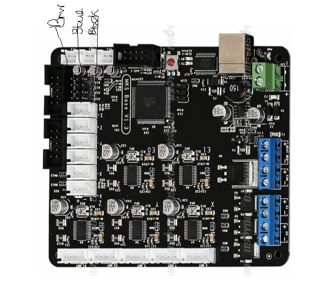
I received a solid answer on this outside the forum. The order of the SN04-N wires on the MKS Base v1.2 board from top to bottom should be Black, Blue, Brown. The sensor is wired in this way on my Migbot and the sensor is running correctly (though still working on getting the position right!).
In answer to my other question about running the four wires of two 40mm fans into a single red and single black wire, this is also fine. I was told it isn't necessary to up the wire gauge, but since I had only 20 and 24 AWG, I went with the 24 AWG.
Hope this helps others.
Thank you so much for sharing this, spent ages looking for the correct wiering for SN04-N, got the light on my sensor today, so hopefully it will be working.
Edited 1 time(s). Last edit at 08/09/2016 05:09AM by Taisiya.
|
Re: Migbot Prusa i3 Unofficial Support Thread August 19, 2016 09:48AM |
Registered: 8 years ago Posts: 17 |
Quote
AccidentalWisdom
I received a solid answer on this outside the forum. The order of the SN04-N wires on the MKS Base v1.2 board from top to bottom should be Black, Blue, Brown. The sensor is wired in this way on my Migbot and the sensor is running correctly (though still working on getting the position right!).
Hi, Are you sure about this order to wire the sensor, I feel like my sensor is working in opposit order, when it touched the plate it lights off and lights on any other case, does anybody know how to fix this?
Many thanks
|
Re: Migbot Prusa i3 Unofficial Support Thread August 19, 2016 02:30PM |
Registered: 13 years ago Posts: 50 |
|
Re: Migbot Prusa i3 Unofficial Support Thread August 19, 2016 02:36PM |
Registered: 8 years ago Posts: 269 |
Quote
Taisiya
Quote
AccidentalWisdom
I received a solid answer on this outside the forum. The order of the SN04-N wires on the MKS Base v1.2 board from top to bottom should be Black, Blue, Brown. The sensor is wired in this way on my Migbot and the sensor is running correctly (though still working on getting the position right!).
Hi, Are you sure about this order to wire the sensor, I feel like my sensor is working in opposit order, when it touched the plate it lights off and lights on any other case, does anybody know how to fix this?
Many thanks
You've wired it incorrectly. Check http://reprap.org/wiki/Migbot_Prusa_i3 for the wiring. It sounds like you have the signal wire mixed up with +5v or GND
Edited 1 time(s). Last edit at 08/19/2016 02:38PM by Ax.
|
Re: Migbot Prusa i3 Unofficial Support Thread August 19, 2016 03:57PM |
Registered: 8 years ago Posts: 17 |
Quote
Ax
You've wired it incorrectly. Check http://reprap.org/wiki/Migbot_Prusa_i3 for the wiring. It sounds like you have the signal wire mixed up with +5v or GND
OK, so I have double checked I have Black, Blue, Brown from top to buttom plugged into negative pole z-
SN04-N2 sensor with following markig
BK LOAD,NPN signal
BU 0V-NC 300mA -
BN 6-36V +
So shall I try to change it to brown, blue, black?
or I have found pic for NPN NC sensors showing diagram
Brown +
Black
Blue -
many thanks
Edited 1 time(s). Last edit at 08/19/2016 04:02PM by Taisiya.
|
Re: Migbot Prusa i3 Unofficial Support Thread August 19, 2016 04:25PM |
Registered: 8 years ago Posts: 269 |
Quote
Taisiya
Quote
Ax
You've wired it incorrectly. Check http://reprap.org/wiki/Migbot_Prusa_i3 for the wiring. It sounds like you have the signal wire mixed up with +5v or GND
OK, so I have double checked I have Black, Blue, Brown from top to buttom plugged into negative pole z-
SN04-N2 sensor with following markig
BK LOAD,NPN signal
BU 0V-NC 300mA -
BN 6-36V +
So shall I try to change it to brown, blue, black?
or I have found pic for NPN NC sensors showing diagram
Brown +
Black
Blue -
many thanks
The way the board works is that the top pin (closest to the USB and 12-24v in) is signal, middle pin is 0v, bottom pin is +5v. So it looks like you have +5v and signal swapped, try flipping the plug 180 degrees
|
Re: Migbot Prusa i3 Unofficial Support Thread August 20, 2016 01:02AM |
Registered: 8 years ago Posts: 111 |
Here is an interesting goody that I came across just browsing around.
It looks like a purpose built SSR-ish thing made specifically for 3D printer heat beds. thoughts?
SSR replacement
Edit- just ordered one. Will try it out when it arrives.
Edited 1 time(s). Last edit at 08/20/2016 01:18AM by veaceonee.
It looks like a purpose built SSR-ish thing made specifically for 3D printer heat beds. thoughts?
SSR replacement
Edit- just ordered one. Will try it out when it arrives.
Edited 1 time(s). Last edit at 08/20/2016 01:18AM by veaceonee.
|
Re: Migbot Prusa i3 Unofficial Support Thread August 20, 2016 03:56AM |
Registered: 8 years ago Posts: 17 |
Quote
Ax
The way the board works is that the top pin (closest to the USB and 12-24v in) is signal, middle pin is 0v, bottom pin is +5v. So it looks like you have +5v and signal swapped, try flipping the plug 180 degrees
Hi guys,
sorry for so many questons, but I am thinking now that either my sensor is faulty or the software of the base I got MK base 1.4
so far I have tried the following combinations, see attached pic as the originally advised, in this sensor lights off when touching any metal part and steady light all other time.
BK LOAD,NPN signal
BU 0V-NC 300mA -
BN 6-36V +
I have also tried to plug it in positive z pole and the result is the same.
tried to change the order to, however in this case the sensor doesn't light up at all as I think the signal should be at the top, as marked on the base
BN 6-36V +
BU 0V-NC 300mA -
BK LOAD,NPN signal
also tried to change the order to below when in negative z pole, however in this case the sensor doesn't light up as well
BK LOAD,NPN signal
BN 6-36V +
BU 0V-NC 300mA -
so are there any other sugestions?
many thanks.
Edited 2 time(s). Last edit at 08/20/2016 03:58AM by Taisiya.
|
Re: Migbot Prusa i3 Unofficial Support Thread August 20, 2016 04:20AM |
Registered: 8 years ago Posts: 17 |
Quote
kareem613
I just upgraded mine to a 24V power supply. I did the PID autotune and that looks all setup right.
Here's my issue. The Z-Probe is permanently reporting triggered. The light is on no matter how far away it is from the bed.
The label on it says it's good for 24V. Any ideas on what might be wrong?
Is there something to adjust on the board or the in the firmware?
Hi,did you solve the issue above with your sensor? please share the solution if you found it, as it looks that I have the same issue,
I think I am on 24V as well.
Many thanks.
|
Re: Migbot Prusa i3 Unofficial Support Thread August 24, 2016 07:47PM |
Registered: 8 years ago Posts: 111 |
Quote
veaceonee
Here is an interesting goody that I came across just browsing around.
It looks like a purpose built SSR-ish thing made specifically for 3D printer heat beds. thoughts?
SSR replacement
Edit- just ordered one. Will try it out when it arrives.
It came in today. Got it mounted, but not hooked up yet. Quick Q, will I need to PID the hotbed after it gets hooked up? How important is an accurate PID on a hotbed?

Edited 1 time(s). Last edit at 08/24/2016 07:48PM by veaceonee.
|
Re: Migbot Prusa i3 Unofficial Support Thread August 24, 2016 07:58PM |
Registered: 8 years ago Posts: 269 |
Quote
veaceonee
Quote
veaceonee
Here is an interesting goody that I came across just browsing around.
It looks like a purpose built SSR-ish thing made specifically for 3D printer heat beds. thoughts?
SSR replacement
Edit- just ordered one. Will try it out when it arrives.
It came in today. Got it mounted, but not hooked up yet. Quick Q, will I need to PID the hotbed after it gets hooked up? How important is an accurate PID on a hotbed?
Personally, I always PID the bed as it's more stable, but to answer your question, no you don't have to.
|
Re: Migbot Prusa i3 Unofficial Support Thread September 04, 2016 01:32AM |
Registered: 7 years ago Posts: 2 |
Hi All,
I have just finished reading all 46 pages of this topic with interest.
I brought my Migbot about 2 years ago from Ebay and it was shipped from china. I find it very handy that I can draw somthing up in Freecad, Export it and load it up in Cura. Save the g file to a SD card and print the part out. usb can not be relied on to keep going without an error for the time it takes to print things.
My printer arrived without any instructions at all on how to put it together. Contacted the seller and got no response from there either.
Slowly built it by looking at what photos I could find on the internet. (Where I was living at the time internet access was almost not available (via satellite only)) I worked it out afterwards that it took me 24hours (over about about a week and a half) of playing with and figuring it out from when I opened the box until I started my first print.
Have never really had any issues with it since.
The biggest problem that I have had with it was that I got it with a roll of filament and that roll was thinner and thicker all down its length. This caused a lot of problems with the extruder. (also a good way to convince the other half to let me buy another roll of a different color)
I have only ever printed with PLA on it. Want to try PET.
It arrived here with an all metal extruder and X-carriage which I just thought was standard. I was real surprised when I started reading here as I did not have any of the problems that I have been reading about.
I am looking at updating the the firmware (still got what it came with on it) and going over it for a good over haul as it gets used at least 2 to 3 times a week and it just keeps on going. Looking into just what I should do to it while I am giving it a good service and properly add a few upgrades while I am at it.
Sounds like checking the power supply and the cable to the main board would be a good first move.
The perspex Y-carriage has bowed a bit over time so it will need looking at.
I do not like the way it drags the cable for the bed on the Y-axis so I am slowly printing out a cable chain for this at the moment.
Maybe a cooling fan for the main board.
Power supply fan makes some sounds when I first power up but comes good after about a bit so it could do with a bit of a looking at.
Bed seems to be taking longer than it used to to warm up to 60deg so I should have a look into this.
I thought about adding auto level but sounds like it causes more problems than it fixes. I check the bed level and adjust about once a month and it does not give me any problems.
Just got a couple of questions,
1. How do I go about checking and adjusting the output from the main board to the motors?
2. Has anyone got any other ideas on what I should check?
B.T.W. standard bed, not large.
Dave W...
Queensland
Australia.
|
Re: Migbot Prusa i3 Unofficial Support Thread September 05, 2016 09:54AM |
Registered: 8 years ago Posts: 269 |
Quote
Dave_W
Hi All,
I have just finished reading all 46 pages of this topic with interest.
I brought my Migbot about 2 years ago from Ebay and it was shipped from china. I find it very handy that I can draw somthing up in Freecad, Export it and load it up in Cura. Save the g file to a SD card and print the part out. usb can not be relied on to keep going without an error for the time it takes to print things.
My printer arrived without any instructions at all on how to put it together. Contacted the seller and got no response from there either.
Slowly built it by looking at what photos I could find on the internet. (Where I was living at the time internet access was almost not available (via satellite only)) I worked it out afterwards that it took me 24hours (over about about a week and a half) of playing with and figuring it out from when I opened the box until I started my first print.
Have never really had any issues with it since.
The biggest problem that I have had with it was that I got it with a roll of filament and that roll was thinner and thicker all down its length. This caused a lot of problems with the extruder. (also a good way to convince the other half to let me buy another roll of a different color)
I have only ever printed with PLA on it. Want to try PET.
It arrived here with an all metal extruder and X-carriage which I just thought was standard. I was real surprised when I started reading here as I did not have any of the problems that I have been reading about.
I am looking at updating the the firmware (still got what it came with on it) and going over it for a good over haul as it gets used at least 2 to 3 times a week and it just keeps on going. Looking into just what I should do to it while I am giving it a good service and properly add a few upgrades while I am at it.
Sounds like checking the power supply and the cable to the main board would be a good first move.
The perspex Y-carriage has bowed a bit over time so it will need looking at.
I do not like the way it drags the cable for the bed on the Y-axis so I am slowly printing out a cable chain for this at the moment.
Maybe a cooling fan for the main board.
Power supply fan makes some sounds when I first power up but comes good after about a bit so it could do with a bit of a looking at.
Bed seems to be taking longer than it used to to warm up to 60deg so I should have a look into this.
I thought about adding auto level but sounds like it causes more problems than it fixes. I check the bed level and adjust about once a month and it does not give me any problems.
Just got a couple of questions,
1. How do I go about checking and adjusting the output from the main board to the motors?
2. Has anyone got any other ideas on what I should check?
B.T.W. standard bed, not large.
Stepper VREFS can be checked from the Pots next to the driver chips (positive probe) and to the top of the USB socket (negative probe)
I will always recommend using good 14 AWG Siilcone RC wire from the Board to the PSU and the same type of 16AWG wire from the Board to bed and junking any existing heavy current carrying wire on the printer, it's grossly under-sized and could cause a fire. Automotive ring Crimps on the AC wires to the PSU and on the 14 AWG wire from the PSU to the board also helps a lot, especially with temp stability. If you have auto levelling, junk the springs and print out 4 spacers for the bed these need to be in either PETG or ABS, this should negate the warp on the Acrylic.
I will also always recommend getting rid of the MK8 extruder setup and putting in an E3D Lite6 (£21 + shipping outside of the EU) you will notice the difference.
Firmware-wise, junk the existing configuration, and take mine. I have an RC7 version in the works, but I need to work out a decent way to get the probe offset. If you're not using Auto Levelling, use the mesh levelling and junk the springs again with my firmware, it's all then done in software and compensates for any bowing, however slight, you have on the bed.
Links for everything can be found on the wiki - [reprap.org]
|
Re: Migbot Prusa i3 Unofficial Support Thread September 10, 2016 08:16AM |
Registered: 8 years ago Posts: 16 |
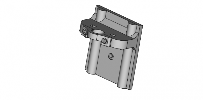
I believe I've encountered a difficult problem. I've bought and sold this kit before and I recently received my third kit which I wanted to keep for myself.
The aluminum block on the extruder assembly has misaligned screw holes with the extruder motor.
What are my options for fixing this? 3dprintersonlinestore.com is refusing to help with this problem.
[imgur.com]
[imgur.com]
Edited 2 time(s). Last edit at 09/10/2016 08:18AM by kaffemustasj.
The aluminum block on the extruder assembly has misaligned screw holes with the extruder motor.
What are my options for fixing this? 3dprintersonlinestore.com is refusing to help with this problem.

[imgur.com]

[imgur.com]
Edited 2 time(s). Last edit at 09/10/2016 08:18AM by kaffemustasj.
|
Re: Migbot Prusa i3 Unofficial Support Thread September 10, 2016 01:34PM |
Registered: 8 years ago Posts: 269 |
Quote
kaffemustasj
I believe I've encountered a difficult problem. I've bought and sold this kit before and I recently received my third kit which I wanted to keep for myself.
The aluminum block on the extruder assembly has misaligned screw holes with the extruder motor.
What are my options for fixing this? 3dprintersonlinestore.com is refusing to help with this problem.
[imgur.com]
[imgur.com]
2 options -
1) Swap for an E3D if you can print a mount
2) I have spares (due to using E3D Lite6s on my 3) so if you're willing to pay postage I can send you one if you want to keep the MK8, (which frankly are horrid imo).
|
Re: Migbot Prusa i3 Unofficial Support Thread September 10, 2016 06:20PM |
Registered: 8 years ago Posts: 16 |
|
Re: Migbot Prusa i3 Unofficial Support Thread September 11, 2016 09:08AM |
Registered: 8 years ago Posts: 269 |
Quote
kaffemustasj
Wouldn't it be hard to switch to E3D and bowden when I'll have a semi difficult time getting printed parts, or can it be done?
Thanks! Did you mean you have spare E3D mounts or spares of the MK8 aluminum block?
I'll definitely look into shipping and postage! What state do you live in?
I'm in the UK, although untracked postage to the US is cheap, for a block it'll be around £5.
E3D Doesn't need to be Bowden. You can get someone else to print the mount for you or you can use 3D Hubs.
|
Re: Migbot Prusa i3 Unofficial Support Thread September 11, 2016 10:08AM |
Registered: 8 years ago Posts: 16 |
Quote
Ax
I'm in the UK, although untracked postage to the US is cheap, for a block it'll be around £5.
E3D Doesn't need to be Bowden. You can get someone else to print the mount for you or you can use 3D Hubs.
Thanks mate you're a life saver!
I live in norway so postage should be pretty cheap and fast as well!
Let's do the details over PM?
|
Re: Migbot Prusa i3 Unofficial Support Thread September 24, 2016 01:10PM |
Registered: 8 years ago Posts: 269 |
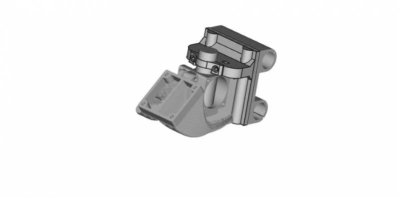
So, I've been busy, my print queues have been huge and I've not had time to really give my Migbots much love. As I've got a small bit of down time I've sat down and redesigned the mount for the E3D Lite6s on them. Historically, I was always anti-bowden extruder on the Migbot however, with the knowledge I have now of this set up and further use of the Migbots, unless you print a lot of flexibles, then bowden is probably the best option for these printers to reduce moving mass on the X axis to avoid torsional stresses if moving over 60mm/s. So, I've come up with this:
This cannot be used with the stock firmware, nor my RC6 firmware as offsets will be way off. It's also designed to be used with my FB2020 CoreXY layer fan, as shown above. The X Axis Bearing carrier has also been modified to remove the endstop tab (not shown) to allow the hot end to be put in the middle of the mount, it will not be possible to use this without the SN04 sensor, yet, as the mount is a lot higher than standard, so the standard endstop mount will not work as it brings the whole carriage assembly lower to the bed increasing Z movement by 5-10mm. I'll be uploading correct firmware, STLs and other parts as soon as I've got it all tested.
With regards to my firmware, I have a working Marlin RC7 large bed version which is printing extremely well, and has produced some of the best results I've had on a Migbot. I'll be pushing it to Github soon.
|
Re: Migbot Prusa i3 Unofficial Support Thread September 25, 2016 12:07PM |
Registered: 8 years ago Posts: 269 |
[www.thingiverse.com] - mount uploaded, untested as yet, but thrown to the crowd to test.
|
Re: Migbot Prusa i3 Unofficial Support Thread September 25, 2016 01:24PM |
Registered: 13 years ago Posts: 50 |
|
Re: Migbot Prusa i3 Unofficial Support Thread September 25, 2016 01:30PM |
Registered: 8 years ago Posts: 269 |
|
Re: Migbot Prusa i3 Unofficial Support Thread September 29, 2016 06:18PM |
Registered: 8 years ago Posts: 111 |
|
Re: Migbot Prusa i3 Unofficial Support Thread October 07, 2016 02:46AM |
Registered: 8 years ago Posts: 26 |
Sorry if this has been covered before but does anyone know if it is possible to extend the range of the proximity sensor for bed detection?
I have just covered the bed with a sheet of PEI and now that the sensor has to read beyond the print surface to the aluminium it literally has to touch the PEI to get the correct print height for the first layer. Now the sensor has to sit lower than the nozzle so other than scraping across the PEI it will now crash into the print.
Is there something in the firmware that can be changed or another sensor that will detect at a further distance?
|
Re: Migbot Prusa i3 Unofficial Support Thread October 11, 2016 06:59AM |
Registered: 8 years ago Posts: 111 |
|
Re: Migbot Prusa i3 Unofficial Support Thread October 16, 2016 07:14AM |
Registered: 8 years ago Posts: 26 |
Thanks veaceonee. I have ordered a 5mm sensor to replace the standard item. Hopefully it will do the trick.
The next thing I'd like to upgrade is the heat bed. Having the large bed has anyone found a suitable silicone heat mat that is the correct size? I'm having trouble finding something in the right size and power that will give quick heat up times.
The next thing I'd like to upgrade is the heat bed. Having the large bed has anyone found a suitable silicone heat mat that is the correct size? I'm having trouble finding something in the right size and power that will give quick heat up times.
|
Re: Migbot Prusa i3 Unofficial Support Thread October 16, 2016 08:00AM |
Registered: 8 years ago Posts: 269 |
Quote
veaceonee
Excitement!! My E3D Lite6 just came in today. Now to find time to install it. Question, is there any Firmware mods I need to do to get it to run good? Anyone using the little silicone heater cover that comes with it?
On my FB2020s I use it and it makes a hell of a difference. Just need to find the cash for 3 blocks and socks, well worth it. Firmware depends on the mount you use.
Quote
IBaz
Thanks veaceonee. I have ordered a 5mm sensor to replace the standard item. Hopefully it will do the trick.
The next thing I'd like to upgrade is the heat bed. Having the large bed has anyone found a suitable silicone heat mat that is the correct size? I'm having trouble finding something in the right size and power that will give quick heat up times.
Hit up Aliexpress. Contact a vendor/manufacturer there, they'll be able to make one to the correct size. Go for a Mains 240v and an SSR (SSR-25DA), heat up times will be about 2-3 mins to 150 and will prob allow you to hit 200 on the bed (!).
Edited 1 time(s). Last edit at 10/16/2016 08:17AM by Ax.
|
Re: Migbot Prusa i3 Unofficial Support Thread October 16, 2016 08:16AM |
Registered: 8 years ago Posts: 269 |
Quick note. I have all 3 of my Migbots converted to Bowden now, this has made a hell of a difference. Firmware-wise, I have Marlin 1.1 RC7 set up for the large bed ( it's a quick change for the standard bed) on these, if you want to use my Bowden set up, drop me a message, I'll sling you the firmware. Extruder-wise, I'm using the Schlotzz extruder on all my machines. I need to mount them correctly, for now they're mounted off the middle bolt of the left Z top acrylic piece.
Top tip for setting the sensor with Marlin 1.1 RC7 (may work for the standard MK8 and Marlin 1.1 RC6 too, can't say, as not tested) - Move the head to the middle of the bed, drop it so you've just got a piece of paper's width with a slight drag between the nozzle and the bed. Loosen off the sensor, now move it so the LED just lights up. Setting the offset is a little trial and error, but start at -0.3, you should be dead on or within about +/-0.2mm of the correct offset from my experience.
Top tip for setting the sensor with Marlin 1.1 RC7 (may work for the standard MK8 and Marlin 1.1 RC6 too, can't say, as not tested) - Move the head to the middle of the bed, drop it so you've just got a piece of paper's width with a slight drag between the nozzle and the bed. Loosen off the sensor, now move it so the LED just lights up. Setting the offset is a little trial and error, but start at -0.3, you should be dead on or within about +/-0.2mm of the correct offset from my experience.
|
Re: Migbot Prusa i3 Unofficial Support Thread October 16, 2016 05:51PM |
Registered: 8 years ago Posts: 111 |
Quote
Ax
On my FB2020s I use it and it makes a hell of a difference. Just need to find the cash for 3 blocks and socks, well worth it. Firmware depends on the mount you use.
I am using your mount you have on Thingiverse (the one with a fan on each side). It is impressive looking. (Note: I wasn't done wiring when the pic was taken, and the large fan goes on the side to cool the board)
I adjusted the reference voltages on the steppers to 1.45V, as I have read in another article, on each stepper. Is that to much? What is the optimal voltage if that is wrong? They are a lot louder than before (considering they were running at less than a volt), when I just move them around via software.
Did a test on the hotbed controller I have mentioned above, what a difference. Bed got to 50C in under a minute. Needs a re-PID but it is better than when it was stock.
|
Re: Migbot Prusa i3 Unofficial Support Thread October 16, 2016 06:32PM |
Registered: 8 years ago Posts: 269 |
Quote
veaceonee
Quote
Ax
On my FB2020s I use it and it makes a hell of a difference. Just need to find the cash for 3 blocks and socks, well worth it. Firmware depends on the mount you use.
I am using your mount you have on Thingiverse (the one with a fan on each side). It is impressive looking. (Note: I wasn't done wiring when the pic was taken, and the large fan goes on the side to cool the board)
I adjusted the reference voltages on the steppers to 1.45V, as I have read in another article, on each stepper. Is that to much? What is the optimal voltage if that is wrong? They are a lot louder than before (considering they were running at less than a volt), when I just move them around via software.
Did a test on the hotbed controller I have mentioned above, what a difference. Bed got to 50C in under a minute. Needs a re-PID but it is better than when it was stock.
Yikes, 1.45v is far too much.. 0.7-0.8v is plenty, hence them being noisy you'll probably find that the motors get damn hot too. Ah, the DD mount, that worked for me for ages until I converted them all to Bowden for less inertial mass on X. Looking at that pic, you may wanna clean your leadscrews and lubricate them


Sorry, only registered users may post in this forum.