Folger Tech 2020 i3 Printer Kit (Official Thread)
Posted by Dan_FolgerTech
|
Re: thermistor location? power cable connections? August 07, 2015 09:06AM |
Registered: 8 years ago Posts: 135 |
Quote
therippa
Quote
Steve_in_NJ
Quote
wderoxas
Quote
Steve_in_NJ
Greetings all,
Here's my first msg here. I have gone through a lot of the thread - tons of great info!
I have two questions, both related to my build which is 90% complete.
1) The tape holding the thermistor to the heatbed let go so I need to re-do it. While I am at it I should ask - where precisely should the bulb-tip be placed? I had it right in the hole in the middle of the heatbed, essentially filling it level with the surface. Is that best?
Yes, it should be inside the hole. Its best if you can make the bulb-tip to be in contact with whatever build plate your going to use on top of the heated bed (glass or aluminum bed).
Uh, WHAT build plate on top of the heated bed? I didn't know there needed to be another plate on top of the red bed. What is appropriate/typical? Can one not print directly on the red bed?
You can, but you probably won't be happy with the results. The Folgertech website tells you you will need a 8x8 piece of glass ( [folgertech.com] ), you can get them on Amazon for ~$13 [www.amazon.com]
lolwut, you can get the same thing not tempered at lowes for $2...... I have been using the same piece of glass since I built my printer and have never had an issue or broken piece of glass.... and I print primarily in ABS with the bed at 100C
My creations/2020 aluminum parts/FolgerTech i3 upgrades [www.thingiverse.com]
|
Re: Folger Tech 2020 i3 Printer Kit (Official Thread) August 07, 2015 10:12AM |
Registered: 9 years ago Posts: 44 |
So here is my first problem that I have received in a while except for some user error with printing. I went to click start on my print via the SD card and my screen blacked out then came back on like this. Now everytime I turn off my printer and turn it back on it comes back when I turn the dial. [imgur.com]
|
Re: Folger Tech 2020 i3 Printer Kit (Official Thread) August 07, 2015 10:57AM |
Registered: 8 years ago Posts: 14 |
|
Re: thermistor location? power cable connections? August 07, 2015 11:41AM |
Registered: 8 years ago Posts: 95 |
Quote
mel0n
Quote
therippa
Quote
Steve_in_NJ
Quote
wderoxas
Quote
Steve_in_NJ
Greetings all,
Here's my first msg here. I have gone through a lot of the thread - tons of great info!
I have two questions, both related to my build which is 90% complete.
1) The tape holding the thermistor to the heatbed let go so I need to re-do it. While I am at it I should ask - where precisely should the bulb-tip be placed? I had it right in the hole in the middle of the heatbed, essentially filling it level with the surface. Is that best?
Yes, it should be inside the hole. Its best if you can make the bulb-tip to be in contact with whatever build plate your going to use on top of the heated bed (glass or aluminum bed).
Uh, WHAT build plate on top of the heated bed? I didn't know there needed to be another plate on top of the red bed. What is appropriate/typical? Can one not print directly on the red bed?
You can, but you probably won't be happy with the results. The Folgertech website tells you you will need a 8x8 piece of glass ( [folgertech.com] ), you can get them on Amazon for ~$13 [www.amazon.com]
lolwut, you can get the same thing not tempered at lowes for $2...... I have been using the same piece of glass since I built my printer and have never had an issue or broken piece of glass.... and I print primarily in ABS with the bed at 100C
What he said.. you can use just about any glass... I sourced mine from an old copier and cut it to size ..
|
Re: Folger Tech 2020 i3 Printer Kit (Official Thread) August 07, 2015 11:46AM |
Registered: 8 years ago Posts: 16 |
|
Re: Folger Tech 2020 i3 Printer Kit (Official Thread) August 07, 2015 12:01PM |
Registered: 8 years ago Posts: 19 |
Quote
Blackbird
My X, Y and Z are colliding with my endstops but they keep moving. The led is triggering on the endstops. I'm using Repetier-Host.
Is there a way to see if my endstops are functioning properly? I'm 100% new to any of this.
Hi Blackbird,
In repetier-host, click on the manual tab and where is shows G-Code. Enter M119 then click send.
If your extruder is away from the end stops (ie: center of the table) none of the end stops should be triggered.
Next hold down with your hand one of the end stops and use M119 command again, It should now show that end stop triggered.
Continue to test each end stop that way. If one or none of them seem to work check the wire for the end stop and connector to the board. There has been issues with poor quality connection between the wire and wire connectors. Also be sure you have plugged them into the correct spot on the ramps board. Each end stop has two position settings on the board (min, max) and the values in the firmware should match. Otherwise the Arduino board has no idea where the start and stop points are for each axis (x, y, z)
I hope that helps
Rick
|
Re: Folger Tech 2020 i3 Printer Kit (Official Thread) August 07, 2015 01:38PM |
Registered: 8 years ago Posts: 135 |
Quote
TimJC
Before I place an order with FT, are there any spare/extra parts that you guys would recommend adding to the order? I already have the graphical LCD coming from BangGood, so I am thinking more along the lined of stuff like extra nozzles, thermistor, heater cartridges, fans, etc.
I would say hot end and extruder parts, though, it makes more sense to just upgrade when yours breaks to one with better tolerances and materials.
So I would say outside the LCD, no, not really. Any parts your going to replace should be upgrade/better parts. The point of the kit is to get a working 3D Printer, I would say from there to replace anything that breaks with upgrade parts.
Edited 2 time(s). Last edit at 08/07/2015 01:40PM by mel0n.
My creations/2020 aluminum parts/FolgerTech i3 upgrades [www.thingiverse.com]
|
Re: Folger Tech 2020 i3 Printer Kit (Official Thread) August 07, 2015 01:54PM |
Registered: 11 years ago Posts: 18 |
Mark,
As far as glass was concerned I went to lowes and purchased one piece of 24" x 26" 3/32" thickness clear replacement glass for $8.36. I had them cut it into 8x8x8 squares and ended up with nine pieces. They charge for cuts after the first two but the cost is minimal something like 20₵ per cut. It took three cuts and cost less than $9 for nine pieces (not counting taxes). There was two inches of waste but they threw it in their recycle bin and wrapped my nine pieces. I did it this way so I did not have to clean the glass immediately before printing again.
The cut pattern Looks like this:
Red represents the cuts made.
As far as glass was concerned I went to lowes and purchased one piece of 24" x 26" 3/32" thickness clear replacement glass for $8.36. I had them cut it into 8x8x8 squares and ended up with nine pieces. They charge for cuts after the first two but the cost is minimal something like 20₵ per cut. It took three cuts and cost less than $9 for nine pieces (not counting taxes). There was two inches of waste but they threw it in their recycle bin and wrapped my nine pieces. I did it this way so I did not have to clean the glass immediately before printing again.
The cut pattern Looks like this:

Red represents the cuts made.
|
Re: Folger Tech 2020 i3 Printer Kit (Official Thread) August 07, 2015 03:12PM |
Registered: 8 years ago Posts: 35 |
Quote
TimJC
Before I place an order with FT, are there any spare/extra parts that you guys would recommend adding to the order? I already have the graphical LCD coming from BangGood, so I am thinking more along the lined of stuff like extra nozzles, thermistor, heater cartridges, fans, etc.
Heat break tubes with PTFE - the one they ship seems to wear and jam really quickly. I'm not even sure its actually PTFE in their tube, it seemed to melt away pretty quick. I bought some third party ones from ebay and I'm still on my first new one and have printed more with it than with the one included in the kit.
|
Re: Folger Tech 2020 i3 Printer Kit (Official Thread) August 07, 2015 03:15PM |
Registered: 8 years ago Posts: 35 |
Quote
Nargousias
Mark,
As far as glass was concerned I went to lowes and purchased one piece of 24" x 26" 3/32" thickness clear replacement glass for $8.36. I had them cut it into 8x8x8 squares and ended up with nine pieces. They charge for cuts after the first two but the cost is minimal something like 20₵ per cut. It took three cuts and cost less than $9 for nine pieces (not counting taxes). There was two inches of waste but they threw it in their recycle bin and wrapped my nine pieces. I did it this way so I did not have to clean the glass immediately before printing again.
The cut pattern Looks like this:
Red represents the cuts made.
I did something similar. Its so cheap and convenient to have a couple sheets lined up with blue tape PLA, and a couple with glue stick for ABS. Just grab the sheet you want, load the filament, level the bed, and go.
|
Re: Folger Tech 2020 i3 Printer Kit (Official Thread) August 07, 2015 10:21PM |
Registered: 8 years ago Posts: 14 |
It does help! A lot! Thanks!Quote
rrowan327
Quote
Blackbird
My X, Y and Z are colliding with my endstops but they keep moving. The led is triggering on the endstops. I'm using Repetier-Host.
Is there a way to see if my endstops are functioning properly? I'm 100% new to any of this.
Hi Blackbird,
In repetier-host, click on the manual tab and where is shows G-Code. Enter M119 then click send.
If your extruder is away from the end stops (ie: center of the table) none of the end stops should be triggered.
Next hold down with your hand one of the end stops and use M119 command again, It should now show that end stop triggered.
Continue to test each end stop that way. If one or none of them seem to work check the wire for the end stop and connector to the board. There has been issues with poor quality connection between the wire and wire connectors. Also be sure you have plugged them into the correct spot on the ramps board. Each end stop has two position settings on the board (min, max) and the values in the firmware should match. Otherwise the Arduino board has no idea where the start and stop points are for each axis (x, y, z)
I hope that helps
Rick
I believe my RAMPS board is defective. I was having problems with my X endstop not triggering properly. I was adjusted the configuration.h settings (I was having the typical shifty x-asix movement) and reflashed the board and my Y axis suddenly went haywire and pushed past the endstop and crashed down onto the bed. Since then the Y axis hasn't moved well and is squeaking and none of the endstops work. They all light up red when the switch is pushed but they're showing triggered when I m119 regardless of what I've done. I've changed the settings in configuration.h to false and true but nothing makes any difference.
So I've ordered a replacement RAMPS (the more expensive one animoose posted) and replacement endstops just in case. Should hopefully be here by the middle of next week. I suspect a lot of the problems I've been having are due to a poor quality RAMPS. My adjustments in Marlin were simply changing the x_home from 1 to -1. I didn't do anything to cause the endstops to suddenly stop triggering.
|
Re: Folger Tech 2020 i3 Printer Kit (Official Thread) August 07, 2015 10:38PM |
Registered: 8 years ago Posts: 6 |
Quote
RedneckGeek
Quote
blank64
Hi all,
I recently got one of these kits and am mostly done putting it together.
Something that has me worried is that one of my stepper motors seems to have no hold (I can turn it by hand with no effort while the others put up a lot of resistance), the back area where the cords plug in also seems kind of loose compared to the others. Does this mean it is broken? Is it safe to test it out in my ramps board?
The motors are spin freely until they get voltage through them from the controller, then you can't move them. This is normal. You can probably feel the ratcheting from the magnets when you turn the shaft by hand.
What part is loose? You may just need to tighten the screws.
Thanks! I can't feel any ratcheting from the magnets, but I'll plug it all in and see what happens!
The (relatively) loose part is just the white plug part at the back, it's probably not too big a deal.
|
Re: Folger Tech 2020 i3 Printer Kit (Official Thread) August 08, 2015 07:20AM |
Registered: 8 years ago Posts: 5 |
Quote
Blackbird
It does help! A lot! Thanks!Quote
rrowan327
Quote
Blackbird
My X, Y and Z are colliding with my endstops but they keep moving. The led is triggering on the endstops. I'm using Repetier-Host.
Is there a way to see if my endstops are functioning properly? I'm 100% new to any of this.
Hi Blackbird,
In repetier-host, click on the manual tab and where is shows G-Code. Enter M119 then click send.
If your extruder is away from the end stops (ie: center of the table) none of the end stops should be triggered.
Next hold down with your hand one of the end stops and use M119 command again, It should now show that end stop triggered.
Continue to test each end stop that way. If one or none of them seem to work check the wire for the end stop and connector to the board. There has been issues with poor quality connection between the wire and wire connectors. Also be sure you have plugged them into the correct spot on the ramps board. Each end stop has two position settings on the board (min, max) and the values in the firmware should match. Otherwise the Arduino board has no idea where the start and stop points are for each axis (x, y, z)
I hope that helps
Rick
I believe my RAMPS board is defective. I was having problems with my X endstop not triggering properly. I was adjusted the configuration.h settings (I was having the typical shifty x-asix movement) and reflashed the board and my Y axis suddenly went haywire and pushed past the endstop and crashed down onto the bed. Since then the Y axis hasn't moved well and is squeaking and none of the endstops work. They all light up red when the switch is pushed but they're showing triggered when I m119 regardless of what I've done. I've changed the settings in configuration.h to false and true but nothing makes any difference.
So I've ordered a replacement RAMPS (the more expensive one animoose posted) and replacement endstops just in case. Should hopefully be here by the middle of next week. I suspect a lot of the problems I've been having are due to a poor quality RAMPS. My adjustments in Marlin were simply changing the x_home from 1 to -1. I didn't do anything to cause the endstops to suddenly stop triggering.
Probably not your RAMPS board. Look at the schematic of the ramps, its nothing more then a connection hub. The only active components on the ramps board itself is the MOSFET's that drive the heaters. The rest of it is just a way to let the stepper drivers interface with the Mega board and the stepper motors themselves. I had to modify my configuration file to tell the driver that I only had home switch and not min max limit switch. Also it's likely you may have your axis's backwards, If you reverse the stepper motor connection on the board it will invert the axis, the reason this is important is because if you do it in software, your reversing the reversing but that's also reversing where it thinks the limit switch is..... yea its all sorts of confusing.
|
Re: Folger Tech 2020 i3 Printer Kit (Official Thread) August 09, 2015 08:02PM |
Registered: 8 years ago Posts: 7 |
Quote
kn4ud
I have also noticed in all my prints at the end it seems to not completely finish.
Add M400 at the top of your end gcode, this command clears your buffer before executing the X axis home.
Your end gcode must look somewhat like this
M400 ; wait for buffer to clear
M104 S0 ; turn off temperature
G28 X0  ; home X axis
M84     ; disable motors
|
Re: Folger Tech 2020 i3 Printer Kit (Official Thread) August 09, 2015 08:25PM |
Registered: 8 years ago Posts: 121 |
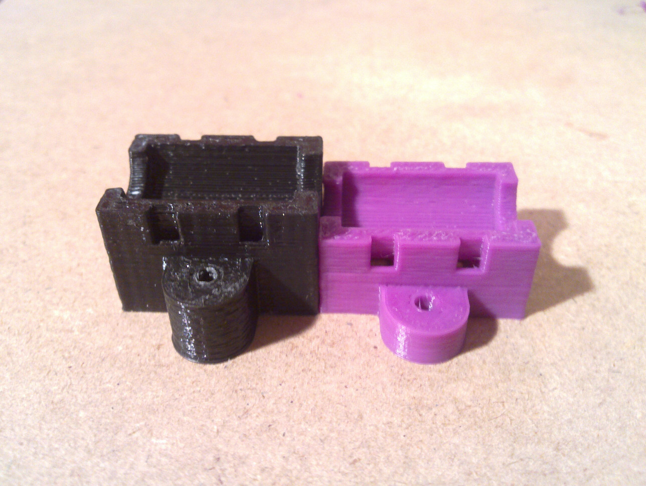
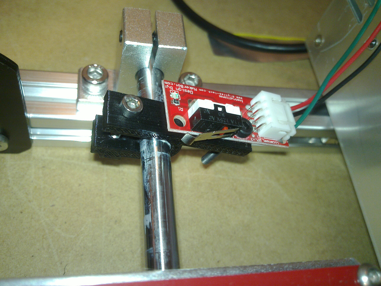
I'm working on modifying the x-carriage design by wderoxas, I'm trying to add a adjustable z-endstop screw. I'm having a hell of time since I have never used any type of 3d modeling programming. I will keep plugging away at it but no clue what I'm doing yet!!!
[dl.dropboxusercontent.com]
[dl.dropboxusercontent.com]
|
Re: Folger Tech 2020 i3 Printer Kit (Official Thread) August 09, 2015 08:52PM |
Registered: 8 years ago Posts: 285 |
Quote
[email protected]
I'm working on modifying the x-carriage design by wderoxas, I'm trying to add a adjustable z-endstop screw. I'm having a hell of time since I have never used any type of 3d modeling programming. I will keep plugging away at it but no clue what I'm doing yet!!!
[dl.dropboxusercontent.com]
Did you import the model as a STL. If you did, remember to try to remove as many unnecessary lines as possible. It will make working with the model much easier.

|
Re: Folger Tech 2020 i3 Printer Kit (Official Thread) August 09, 2015 09:00PM |
Registered: 8 years ago Posts: 6 |
So I have now finished the build, but am now having some problems trying it out with repetier: (I tried both the marlin included in the drive folder, and the one posted a few pages back)
My y-axis motor doesn't seem to be able to turn the belt (it either barely turns, or skips the belt entirely while turning), I used one of the included belt tensioners so it's pretty tight.
My x-axis motor doesn't seem to be working at all (Although it gets a bit warm after a couple of minutes)
Only one of my z-axis motors is actually turning (the one which I can turn by hand while off), I tried switching where the 2 motors are plugged in, but in each case the same one turns.
Has anyone experienced any of these problems?
|
Re: Folger Tech 2020 i3 Printer Kit (Official Thread) August 09, 2015 09:46PM |
Registered: 8 years ago Posts: 121 |
Quote
Mach
Quote
[email protected]
I'm working on modifying the x-carriage design by wderoxas, I'm trying to add a adjustable z-endstop screw. I'm having a hell of time since I have never used any type of 3d modeling programming. I will keep plugging away at it but no clue what I'm doing yet!!!
[dl.dropboxusercontent.com]
Did you import the model as a STL. If you did, remember to try to remove as many unnecessary lines as possible. It will make working with the model much easier.
I imported the two models as STL files working on combining them getting used to the push/pull tools. I'm on vacation/holiday so sitting by the ocean and drinking ALOT so not real sure how far I'll get on it.
|
Re: Folger Tech 2020 i3 Printer Kit (Official Thread) August 09, 2015 10:21PM |
Registered: 8 years ago Posts: 367 |
I made a similar change to the idler end for the motor, by adding a cylinder with a hole for a M3 screw. It makes adjusting the Z end position easier than moving the end stop. I did this by important the model into Blender, creating a new object for the cylinder with the M3 hole in it, and merging them with a Boolean union operator. However, I do have a little experience with Blender from things I've done in the past. It's hard to get started with.
See my blog at [moosteria.blogspot.com].
See my blog at [moosteria.blogspot.com].
|
Re: Folger Tech 2020 i3 Printer Kit (Official Thread) August 09, 2015 11:14PM |
Registered: 8 years ago Posts: 14 |
I've re-done the bearing blocks for the Y-axis. It was taking a while to level the bed with the stock ones. The springs at the front of the bed had to be compressed nearly all the way and the back ones were barely compressed. I also made them a little shorter. Now the belt carriage is more inline with the belt and it gives me a few mm on the Z-axis. I also had to make an alteration for the Y-axis end stop mount. And while putting it all back together I managed to cross-thread one of the M3 bolts. Luckily the local ACE Hardware had some in stock. I bought a few extras of various lengths along with some lock nuts and some washers.
I had first tried to model this part in Sketchup but was having trouble with the routes for the zip ties. The free version doesn't do boolean operations and the intersect function doesn't always work right, especially with curved surfaces.
I managed to get the part modeled in FreeCAD, but it seems to take forever just to do the simplest things.
|
Re: Folger Tech 2020 i3 Printer Kit (Official Thread) August 10, 2015 01:58AM |
Registered: 8 years ago Posts: 66 |
I've been hammering the printer with a lot of things and finally started to hear a grinding on the LM8UU for the bed (single bearing side). I replaced all three with printed ones which are actually working very well after a little break in. I'm going to try a different style soon though as these ones seems to hang up a bit. No more Grindy sounds!
Currently printing a new extruder/hotend mount on it for the Geeetech as I'm thinking it wobbles too much and is giving bad precision.
Edited 1 time(s). Last edit at 08/10/2015 01:59AM by CheopisIV.
Sigil Pickups || Stunt Monkey Pedals
Currently printing a new extruder/hotend mount on it for the Geeetech as I'm thinking it wobbles too much and is giving bad precision.
Edited 1 time(s). Last edit at 08/10/2015 01:59AM by CheopisIV.
Sigil Pickups || Stunt Monkey Pedals
|
Re: Folger Tech 2020 i3 Printer Kit (Official Thread) August 10, 2015 02:40AM |
Registered: 8 years ago Posts: 14 |
Are you sure the bearing with teeth on the motor isn't puched too close to the motor body? If it sits right against the motor housing and you have the set screws tightened, it won't spin properly. Easy thing to overlook while putting everything together.Quote
blank64
So I have now finished the build, but am now having some problems trying it out with repetier: (I tried both the marlin included in the drive folder, and the one posted a few pages back)
My y-axis motor doesn't seem to be able to turn the belt (it either barely turns, or skips the belt entirely while turning), I used one of the included belt tensioners so it's pretty tight.
My x-axis motor doesn't seem to be working at all (Although it gets a bit warm after a couple of minutes)
Only one of my z-axis motors is actually turning (the one which I can turn by hand while off), I tried switching where the 2 motors are plugged in, but in each case the same one turns.
Has anyone experienced any of these problems?
|
Re: Folger Tech 2020 i3 Printer Kit (Official Thread) August 10, 2015 04:16AM |
Registered: 9 years ago Posts: 45 |
This may have already all been covered, but I wanted to get some of my preliminary feedback about the printer. My little brother decided he wanted to get int 3d printing, I'm an engineer working on a large, and honestly totally ridiculous delta, but figured it's got enough issues, a kit printer might help me get parts made for it rather than having to send out to shapeways. So I ordered 2, and we're getting them up and running.
Biggest issue: to those who say they got the kit assembled in 4 hours are you *SURE* you have those t nuts rotated in the slots 90 degrees? All of them? They're awful. I know misumi's preinstall t nuts cost a bit, but those (m4) post install t nuts are absolute garbage. Spent hours on single bolts sometimes. Was ready to go to the garage make some thermite just to burn those witchlike t nuts. They've gotta go. Pissed me off something fierce!
I got the aluminum frame because it should be easier to make bigger in the future if I decide I want to. I really appreciate the use of the l brackets on the corners rather than machining for misumi's special connectors. It will make the upgrade *dirt cheap* in the future if I decide to do it, so thanks so much for that. However, you also included some long lead wires, even better, except one thing. I noticed you included an extra driver board. Might this be because of some weird random deaths of stepper drivers? Long leads send huge LC spikes into the driver. My aforementioned delta has this issue as I have the electronics in the bottom, wires run to the top...1440mm away and another 150mm into the extruders. It's almost instant death at that length. The ramps designers pit bull capacitors but used low esr solid caps for them, not what pololu recommends. To keep my extruders running I had to solder in a run of the mill electrolytic cap, I chose a large value to be safe of 470uF across the vmot pins. The included leads are certainly nowhere near this length, however, pololu recommends keeping the leads short. I'm torn now. I have the crimp tool, I can easily shorten the leads and maybe extend the life of my drivers, but I'll probably upgrade to either raps128 or at least drv8825 boards. But my younger brother is in college and doesn't have money to blow, so shorten the leads, solder a cap in, or just leave it...not sure yet, but if minimal leads were included, it wouldn't be an issue.
Tolerance! Tolerance! TOLERANCE! Those sk8s are bad. Wouldn't be an issue of the m5 bolts included were m5x10. Even on the smallest night sk8, the 10 shouldn't have bottomed out, but with the 8's they hang by a thread or two only! I had to dremel down the top of the bottom shoulders so I didn't adjust the height they were holding the rod, but let me get the puny 8mm bolt through, which wasn't even an 8mm bolt, it was a 7.25-7.75mm bolt. Gotta account for tolerances. The sk8's are clearly forged and not machined to any tolerance at all. Either let us know ahead of time we will need to dremel so we don't sit there wondering if we're stupid, or get the manufacturer to enforce some tolerance. I realize the price of the kit is a deciding factor, so it's not like we will see machined parts. So the instructions at the least would be helpful!
Dimensions: certainly people buying a 3d printer kit can do basic math. Thanks for the compliment. However, it's still a time suck calculating the offsets for the sk8s. My little brother guessed 96.96mm from the outside, impressive since when I did the calculations I got 96.92, but I had to sit there measuring bolt hole distances, adding/subtracting tolerances until I got the correct dimensions and the calculations were easy. Would have made me soooooooo much happier to have had the dimensions. But that leads me to another missing item! Instructions on tightening down the sk8s! It just says later. Also missing was to cut the 16g wire into 2 240mm lengths and use the rest on the heated bed. Fortunately we skipped the heated bed part because I was going to teach my brother to solder. I didn't realize how big those pads were, or how well of a heatsink that board would act as, so I ended up just making the connections. Oh, and I didn't study the board closely, but the reason to bridge the gap on 2 and 3ixnt to run at 24v, it's because we aren't running 24V with this kit. My guess is you can hook the thing up in one serial loop, or two parallel loops, depending on voltage. so that line about 24V in the instructions is likely to confuse newbies. Just say without it the bed won't reach max temp, or it just wo t work properly with a 12V supply like this kit uses (to spell out they don't have24V anything on this kit!)
I saw there were no more crimp pins and just a pre-crimped solder on end. I take it that was supposed to be for the thermistor since crushing with pliers doesn't really work on those connectors. I just crimped them with my own pins/blocks. I looked at the bed and that one has them crimped. I take it these are coming from 2 different suppliers, one that will crimp and one that won't? My original thought was to say have them just crimp the extruder! However, 2 for 2 beds had crimp issues with the thermistor wires. One of them they only crimped insulation lol. No wonder we've got an open circuit! (Kudos to my brother for checking! I assumed he'd broken a wire in wrangling the wires!). Regardless, something should also be done here. Perhaps like before just include a short length of ore crimped wire, but rather than telling people to kapton tape like with the fan wires, just include a few short lengths of heat shrink tubing. Those fan wires are plenty of distance away from the hot end for heat shrink, and thermistor wires are certainly far enough away! I happened to have a for parts power supply with the female of the fan connectors around, 2 of them no less, so I used that...and since they had the wrong color wires in the wrong pins, I used some long sections of heat shrink tubing to cover up what I had done! (also used those to teach soldering)
Marlin....in the one page of comments I read I saw issues with configuration.h. I had them too. I can send you what I'm running now that works, but I'm new to Cartesian printers with this kit (new to deltas with my ridiculous bot too). Still managed to print a Cali ration cube with my config though so it works. I'd just *REALLY* like to reverse the x and y axes. It's fine if you look at it from the power supply side...but it's backwards otherwise. Minor annoyance. Since I'm a software engineer, this was the least of my problems, but lots of people freak out looking at code, so basic firmware issues are enormous insurmountable issues to some...should they be using a kit without help? Probably not. But as far as they're concerned they aren't crazy like me and my delta striking out into uncharted territory! (The issue with it is just in leveling and I think I'm running into repetier bugs since the height map it produces is obvious junk data since it always has a step in my glass of 3mm! My glass is smooth I assure you! )
Lcd kit: I don't know if it's just because I found the kit on a conglmeration of kits site, or not, but were/are/could there be full graphic lcd kits offered? How about hardware to mount the kits somewhere. I know, it ruins the fun of printing your own out....but still!. How about z probes. Even just microswitch based ones with printed parts. I have the microswitches/servos on order, and I think I've got one printer leveled well enough to print. I'm so sick of bed leveling thanks to my monster is have just bought 2 z probes without a second thought! Maybe that's just me lol.
Motor settings: this one got me a bit, and I still don't know what to set the y axis motor to. I went to the "regular" i3 page and found the 2.6Kg motor specs. I guess you buy enough bulk you get the motor companies to only include your information on them though, and not the manufacturer model number so I couldn't look up the current values. I set it the same as the others, .4A, figuring that should be safe. Even that was an adventure. You include pololu documentation, but those aren't name brand pololus, so I had to check out the sense resistors. Again, already been through this with other generic "step stick" type drivers, so I knew to look at the pair of resistors off to the side of the chip labeled s1 and s2, use my phone camera as a magnifying glass, and read the resistor value to see its 0.1 ohms, meaning you set vref to .32 if memory serves me. Oh, and why the ceramic screwdriver? Step sticks always use pots you can read with the screwdriver. Use a conductive screwdriver put your dmm positive lead on the screwdriver, negative lead to the power supply ground (motor supply if you have separate) and you can read vref as you adjust it letting you set it far more accurately. (The one thing I like about stepsticks!). Oh, I also assumed the extruder was the same 2.6 kgcm motor, but I didn't look closely for numbers. I just again set it to .4A and it seems to be ok. Still would be nice to at least have the motor data sheets! I mean, I applaud trying to teach people where to get the information to help themselves, but finding a datasheet for a motor with only your name on it isn't easy! Even the "regular" i3 page didn't have it. I didn't look beyond it. Same with rsense. I mean, yes, a newbie could find the information and learn, but they feel a huge sense of risk applying a bunch of new knowledge all at once knowing if one single item was off they may fry their new toy! At the very least give them r sense!
Some basic settings would be nice too. Perhaps these are covered somewhere, but just done if the stuff for slicer like extruder speed. I honestly don't remember how I got my number for my delta, and I'm not even sure if it was right since slicer passed me off, so did cura...but I'm an engineer....I want control! Skein forge! Though it needs work as well....I know I'm going to end up writing code for these things....why did I ever build one?! WHY?. But I digress.
I think that's it. I wanted to post while it's all still fresh. Oh, minor, but there were no m3x18 screws as the instructions stated for use in mounting the endstops. My guess is you got bit by tolerances there as well and went to m3x20's. I just used the m3x20s anyhow. Perhaps I used the m3x18s somewhere else. Not sure. If I did, the two sizes are unnecessary. Might save you money buying in bulk! Oh, and along those lines, what gives with all the m3x25's leftover?! There must be 15 from each kit! Ok, that's really nit picking....so if I remember anything else, I'll post, but I think that's all the major points.
Other than those, I really like this kit. By far those t nuts were the absolute worse. I generally save swear words for when I'm actually passed so people know when not to bother me. Those t nuts had me swearing like a marine for hours. They're really *THAT* bad. I'm already thinking about upgrades, like I just got a cyclops/chimera for the delta, so I have a spare v6 once I mount the chimera/cyclops...though maybe I'll give the v6 to my brother...but maybe that would be mean since he'd have to break everything down to upgrade it . Anyhow, don't take this as angry ranting, it's not. Overall it's a good kit. The unexpected dremeling and unexpected fighting with t nutsjust made it take longer than we had figured it would take to assemble. I love how quiet the thing is though!
Edit: in going to check my real reason for getting online for this, figuring out which hot end its using, I saw the page about the laser cut acrylic parts and that reminded me...orientation of the acrylic! I spent s e time questioning my own intelligence trying to mount the arduino/ramps. Turns out, I had to flip the acrylic, not on the printer z axis as the instructions warn. No, I was able to mount it to the l bracket. I had to flip it on the printers y axis. In other words, the arduino would have mounted to the inside of the printer, not the outside. There are some engraved things I guess are supposed to be component outlines or something saying mount the arduino against this? Not sure...nothing in the directions. I couldn't get a set of holes to line up with the USB port pointing away from the z column though. A short blurb about the engraved stuff would save us from wondering if we're stupid
Edit 2: threaded rod was/is bent. I'm not sure how much this will effect accuracy. Certainly causing unnecessary binding though. I'll probably order replacement from McMaster. Figure even if a 36" section bends in shipping I should be able to get 4 straight sections for 2 printers
Edited 2 time(s). Last edit at 08/10/2015 04:53AM by corry.
Biggest issue: to those who say they got the kit assembled in 4 hours are you *SURE* you have those t nuts rotated in the slots 90 degrees? All of them? They're awful. I know misumi's preinstall t nuts cost a bit, but those (m4) post install t nuts are absolute garbage. Spent hours on single bolts sometimes. Was ready to go to the garage make some thermite just to burn those witchlike t nuts. They've gotta go. Pissed me off something fierce!
I got the aluminum frame because it should be easier to make bigger in the future if I decide I want to. I really appreciate the use of the l brackets on the corners rather than machining for misumi's special connectors. It will make the upgrade *dirt cheap* in the future if I decide to do it, so thanks so much for that. However, you also included some long lead wires, even better, except one thing. I noticed you included an extra driver board. Might this be because of some weird random deaths of stepper drivers? Long leads send huge LC spikes into the driver. My aforementioned delta has this issue as I have the electronics in the bottom, wires run to the top...1440mm away and another 150mm into the extruders. It's almost instant death at that length. The ramps designers pit bull capacitors but used low esr solid caps for them, not what pololu recommends. To keep my extruders running I had to solder in a run of the mill electrolytic cap, I chose a large value to be safe of 470uF across the vmot pins. The included leads are certainly nowhere near this length, however, pololu recommends keeping the leads short. I'm torn now. I have the crimp tool, I can easily shorten the leads and maybe extend the life of my drivers, but I'll probably upgrade to either raps128 or at least drv8825 boards. But my younger brother is in college and doesn't have money to blow, so shorten the leads, solder a cap in, or just leave it...not sure yet, but if minimal leads were included, it wouldn't be an issue.
Tolerance! Tolerance! TOLERANCE! Those sk8s are bad. Wouldn't be an issue of the m5 bolts included were m5x10. Even on the smallest night sk8, the 10 shouldn't have bottomed out, but with the 8's they hang by a thread or two only! I had to dremel down the top of the bottom shoulders so I didn't adjust the height they were holding the rod, but let me get the puny 8mm bolt through, which wasn't even an 8mm bolt, it was a 7.25-7.75mm bolt. Gotta account for tolerances. The sk8's are clearly forged and not machined to any tolerance at all. Either let us know ahead of time we will need to dremel so we don't sit there wondering if we're stupid, or get the manufacturer to enforce some tolerance. I realize the price of the kit is a deciding factor, so it's not like we will see machined parts. So the instructions at the least would be helpful!
Dimensions: certainly people buying a 3d printer kit can do basic math. Thanks for the compliment
. However, it's still a time suck calculating the offsets for the sk8s. My little brother guessed 96.96mm from the outside, impressive since when I did the calculations I got 96.92, but I had to sit there measuring bolt hole distances, adding/subtracting tolerances until I got the correct dimensions and the calculations were easy. Would have made me soooooooo much happier to have had the dimensions. But that leads me to another missing item! Instructions on tightening down the sk8s! It just says later. Also missing was to cut the 16g wire into 2 240mm lengths and use the rest on the heated bed. Fortunately we skipped the heated bed part because I was going to teach my brother to solder. I didn't realize how big those pads were, or how well of a heatsink that board would act as, so I ended up just making the connections. Oh, and I didn't study the board closely, but the reason to bridge the gap on 2 and 3ixnt to run at 24v, it's because we aren't running 24V with this kit. My guess is you can hook the thing up in one serial loop, or two parallel loops, depending on voltage. so that line about 24V in the instructions is likely to confuse newbies. Just say without it the bed won't reach max temp, or it just wo t work properly with a 12V supply like this kit uses (to spell out they don't have24V anything on this kit!) I saw there were no more crimp pins and just a pre-crimped solder on end. I take it that was supposed to be for the thermistor since crushing with pliers doesn't really work on those connectors. I just crimped them with my own pins/blocks. I looked at the bed and that one has them crimped. I take it these are coming from 2 different suppliers, one that will crimp and one that won't? My original thought was to say have them just crimp the extruder! However, 2 for 2 beds had crimp issues with the thermistor wires. One of them they only crimped insulation lol. No wonder we've got an open circuit! (Kudos to my brother for checking! I assumed he'd broken a wire in wrangling the wires!). Regardless, something should also be done here. Perhaps like before just include a short length of ore crimped wire, but rather than telling people to kapton tape like with the fan wires, just include a few short lengths of heat shrink tubing. Those fan wires are plenty of distance away from the hot end for heat shrink, and thermistor wires are certainly far enough away! I happened to have a for parts power supply with the female of the fan connectors around, 2 of them no less, so I used that...and since they had the wrong color wires in the wrong pins, I used some long sections of heat shrink tubing to cover up what I had done!
(also used those to teach soldering)Marlin....in the one page of comments I read I saw issues with configuration.h. I had them too. I can send you what I'm running now that works, but I'm new to Cartesian printers with this kit (new to deltas with my ridiculous bot too). Still managed to print a Cali ration cube with my config though so it works. I'd just *REALLY* like to reverse the x and y axes. It's fine if you look at it from the power supply side...but it's backwards otherwise. Minor annoyance. Since I'm a software engineer, this was the least of my problems, but lots of people freak out looking at code, so basic firmware issues are enormous insurmountable issues to some...should they be using a kit without help? Probably not. But as far as they're concerned they aren't crazy like me and my delta striking out into uncharted territory! (The issue with it is just in leveling and I think I'm running into repetier bugs since the height map it produces is obvious junk data since it always has a step in my glass of 3mm! My glass is smooth I assure you!
)Lcd kit: I don't know if it's just because I found the kit on a conglmeration of kits site, or not, but were/are/could there be full graphic lcd kits offered? How about hardware to mount the kits somewhere. I know, it ruins the fun of printing your own out....but still!
. How about z probes. Even just microswitch based ones with printed parts. I have the microswitches/servos on order, and I think I've got one printer leveled well enough to print. I'm so sick of bed leveling thanks to my monster is have just bought 2 z probes without a second thought! Maybe that's just me lol. Motor settings: this one got me a bit, and I still don't know what to set the y axis motor to. I went to the "regular" i3 page and found the 2.6Kg motor specs. I guess you buy enough bulk you get the motor companies to only include your information on them though, and not the manufacturer model number so I couldn't look up the current values. I set it the same as the others, .4A, figuring that should be safe. Even that was an adventure. You include pololu documentation, but those aren't name brand pololus, so I had to check out the sense resistors. Again, already been through this with other generic "step stick" type drivers, so I knew to look at the pair of resistors off to the side of the chip labeled s1 and s2, use my phone camera as a magnifying glass, and read the resistor value to see its 0.1 ohms, meaning you set vref to .32 if memory serves me. Oh, and why the ceramic screwdriver? Step sticks always use pots you can read with the screwdriver. Use a conductive screwdriver put your dmm positive lead on the screwdriver, negative lead to the power supply ground (motor supply if you have separate) and you can read vref as you adjust it letting you set it far more accurately. (The one thing I like about stepsticks!). Oh, I also assumed the extruder was the same 2.6 kgcm motor, but I didn't look closely for numbers. I just again set it to .4A and it seems to be ok. Still would be nice to at least have the motor data sheets! I mean, I applaud trying to teach people where to get the information to help themselves, but finding a datasheet for a motor with only your name on it isn't easy! Even the "regular" i3 page didn't have it. I didn't look beyond it. Same with rsense. I mean, yes, a newbie could find the information and learn, but they feel a huge sense of risk applying a bunch of new knowledge all at once knowing if one single item was off they may fry their new toy! At the very least give them r sense!
Some basic settings would be nice too. Perhaps these are covered somewhere, but just done if the stuff for slicer like extruder speed. I honestly don't remember how I got my number for my delta, and I'm not even sure if it was right since slicer passed me off, so did cura...but I'm an engineer....I want control! Skein forge! Though it needs work as well....I know I'm going to end up writing code for these things....why did I ever build one?! WHY?
. But I digress.I think that's it. I wanted to post while it's all still fresh. Oh, minor, but there were no m3x18 screws as the instructions stated for use in mounting the endstops. My guess is you got bit by tolerances there as well and went to m3x20's. I just used the m3x20s anyhow. Perhaps I used the m3x18s somewhere else. Not sure. If I did, the two sizes are unnecessary. Might save you money buying in bulk! Oh, and along those lines, what gives with all the m3x25's leftover?! There must be 15 from each kit! Ok, that's really nit picking....so if I remember anything else, I'll post, but I think that's all the major points.
Other than those, I really like this kit. By far those t nuts were the absolute worse. I generally save swear words for when I'm actually passed so people know when not to bother me. Those t nuts had me swearing like a marine for hours. They're really *THAT* bad. I'm already thinking about upgrades, like I just got a cyclops/chimera for the delta, so I have a spare v6 once I mount the chimera/cyclops...though maybe I'll give the v6 to my brother...but maybe that would be mean since he'd have to break everything down to upgrade it
. Anyhow, don't take this as angry ranting, it's not. Overall it's a good kit. The unexpected dremeling and unexpected fighting with t nutsjust made it take longer than we had figured it would take to assemble. I love how quiet the thing is though!Edit: in going to check my real reason for getting online for this, figuring out which hot end its using, I saw the page about the laser cut acrylic parts and that reminded me...orientation of the acrylic! I spent s e time questioning my own intelligence trying to mount the arduino/ramps. Turns out, I had to flip the acrylic, not on the printer z axis as the instructions warn. No, I was able to mount it to the l bracket. I had to flip it on the printers y axis. In other words, the arduino would have mounted to the inside of the printer, not the outside. There are some engraved things I guess are supposed to be component outlines or something saying mount the arduino against this? Not sure...nothing in the directions. I couldn't get a set of holes to line up with the USB port pointing away from the z column though. A short blurb about the engraved stuff would save us from wondering if we're stupid
Edit 2: threaded rod was/is bent. I'm not sure how much this will effect accuracy. Certainly causing unnecessary binding though. I'll probably order replacement from McMaster. Figure even if a 36" section bends in shipping I should be able to get 4 straight sections for 2 printers
Edited 2 time(s). Last edit at 08/10/2015 04:53AM by corry.
|
Re: Folger Tech 2020 i3 Printer Kit (Official Thread) August 10, 2015 06:12AM |
Registered: 8 years ago Posts: 14 |
|
Re: Folger Tech 2020 i3 Printer Kit (Official Thread) August 10, 2015 09:01AM |
Registered: 8 years ago Posts: 430 |
|
Re: Folger Tech 2020 i3 Printer Kit (Official Thread) August 10, 2015 09:51AM |
Registered: 11 years ago Posts: 335 |
Quote
corry
Biggest issue: to those who say they got the kit assembled in 4 hours are you *SURE* you have those t nuts rotated in the slots 90 degrees? All of them? They're awful. I know misumi's preinstall t nuts cost a bit, but those (m4) post install t nuts are absolute garbage. Spent hours on single bolts sometimes. Was ready to go to the garage make some thermite just to burn those witchlike t nuts. They've gotta go. Pissed me off something fierce!
They are pretty awful (frankly I would have preferred regular pre-assembly nuts and some planning) but there is kind of a trick. If you have tweezers you can rotate them into place and as long as you don't try to back out the screw during assembly they should stay in place.
Also the earlier kits used internal corner brackets (with set-screws) so you only needed like 6 or 8 of the m4 nuts.
The instructions could use work, and I'm pretty sure with proper design they could have really cut down on the number of different fastener types used.
|
Re: Folger Tech 2020 i3 Printer Kit (Official Thread) August 10, 2015 10:05AM |
Registered: 8 years ago Posts: 135 |
Quote
691175002
Quote
corry
Biggest issue: to those who say they got the kit assembled in 4 hours are you *SURE* you have those t nuts rotated in the slots 90 degrees? All of them? They're awful. I know misumi's preinstall t nuts cost a bit, but those (m4) post install t nuts are absolute garbage. Spent hours on single bolts sometimes. Was ready to go to the garage make some thermite just to burn those witchlike t nuts. They've gotta go. Pissed me off something fierce!
They are pretty awful (frankly I would have preferred regular pre-assembly nuts and some planning) but there is kind of a trick. If you have tweezers you can rotate them into place and as long as you don't try to back out the screw during assembly they should stay in place.
Also the earlier kits used internal corner brackets (with set-screws) so you only needed like 6 or 8 of the m4 nuts.
The instructions could use work, and I'm pretty sure with proper design they could have really cut down on the number of different fastener types used.
Actually, the T-nuts aren't that bad once you figure out the technique. I figured it out about half way through my printer. APPLY FORCE. Basically, just pop the nut in, orientation doesn't matter, line up your screw, and push down on the screw with a good amount of force as you tighten it. I can't really explain how it works, but at least 9/10 times it pulls the t-nut up and rotates itself into place with a good amount of bite.
So next time you use a T-nut, push on it really hard as you screw into it and I promise you will be amazed how well/easily it works.
My creations/2020 aluminum parts/FolgerTech i3 upgrades [www.thingiverse.com]
|
Re: Folger Tech 2020 i3 Printer Kit (Official Thread) August 10, 2015 10:13AM |
Registered: 8 years ago Posts: 171 |
Quote
mel0n
Quote
691175002
Quote
corry
Biggest issue: to those who say they got the kit assembled in 4 hours are you *SURE* you have those t nuts rotated in the slots 90 degrees? All of them? They're awful. I know misumi's preinstall t nuts cost a bit, but those (m4) post install t nuts are absolute garbage. Spent hours on single bolts sometimes. Was ready to go to the garage make some thermite just to burn those witchlike t nuts. They've gotta go. Pissed me off something fierce!
They are pretty awful (frankly I would have preferred regular pre-assembly nuts and some planning) but there is kind of a trick. If you have tweezers you can rotate them into place and as long as you don't try to back out the screw during assembly they should stay in place.
Also the earlier kits used internal corner brackets (with set-screws) so you only needed like 6 or 8 of the m4 nuts.
The instructions could use work, and I'm pretty sure with proper design they could have really cut down on the number of different fastener types used.
Actually, the T-nuts aren't that bad once you figure out the technique. I figured it out about half way through my printer. APPLY FORCE. Basically, just pop the nut in, orientation doesn't matter, line up your screw, and push down on the screw with a good amount of force as you tighten it. I can't really explain how it works, but at least 9/10 times it pulls the t-nut up and rotates itself into place with a good amount of bite.
So next time you use a T-nut, push on it really hard as you screw into it and I promise you will be amazed how well/easily it works.
I was about to post this as well. I fought and fought with those then also realized if I just started to screw into them, they rotated right into place for the most part.
Edited 1 time(s). Last edit at 08/10/2015 10:14AM by markts.
|
Re: Folger Tech 2020 i3 Printer Kit (Official Thread) August 10, 2015 10:45AM |
Registered: 9 years ago Posts: 44 |
Quote
zarnold16
So here is my first problem that I have received in a while except for some user error with printing. I went to click start on my print via the SD card and my screen blacked out then came back on like this. Now everytime I turn off my printer and turn it back on it comes back when I turn the dial. [imgur.com]
Okay I still have not figured this out.
 I just broke a blade on my extruder fan, Am I able to run the printer without this while I wait for replacement?
|
Re: Folger Tech 2020 i3 Printer Kit (Official Thread) August 10, 2015 10:47AM |
Registered: 8 years ago Posts: 135 |
Quote
zarnold16
Quote
zarnold16
So here is my first problem that I have received in a while except for some user error with printing. I went to click start on my print via the SD card and my screen blacked out then came back on like this. Now everytime I turn off my printer and turn it back on it comes back when I turn the dial. [imgur.com]
Okay I still have not figured this out.
It will probably be out of balance and noisy, but if it still pushes air and you have a replacement coming, I don't see why not.
My creations/2020 aluminum parts/FolgerTech i3 upgrades [www.thingiverse.com]


Sorry, only registered users may post in this forum.