Folger Tech 2020 i3 Printer Kit (Official Thread)
Posted by Dan_FolgerTech
|
Re: Folger Tech 2020 i3 Printer Kit (Official Thread) January 20, 2016 12:50PM |
Registered: 8 years ago Posts: 268 |
Quote
marc2912
Quote
sonnylowe
Quote
Bert3D
Has anyone tried using one of these aluminum heated build plates with a prox sensor and glass? [r.ebay.com]
I've got a BLTouch on order, but if it doesn't work out, I'm wondering if this would work?
In theory, if the BLTouch is accurate as they claim, it should be better, because it is measuring the distance to the glass surface. Even if the glass is uneven or not sitting flat on the bed, the auto level should still work.
A prox sensor will not work well if you have multiple glass panes in different thicknesses, and want to swap between them, for example. Printing with vs without tape on the bed also creates a tiny variance.
Anyone have any experience or opinions on the BLTouch, or the proximity sensor with aluminum heat plate?
I ran the BLtouch (Yellow) version for a while (I just removed it the other day) and I really liked it, I love the mechanical nature of it and the fact you can actually hear it working ;-) You are correct, it hits the glass, ALM plate, whatever, so it seem it might be a bit more accurate over varying surfaces, especially multi-layered surfaces like glass over ALM. It takes a bit of effrt to get to work, but well worth it when you consider you can run anything, and add any additional surface material and never have to reset the Z offset. If you use a proximity sensor and add say a Buildtak sheet adjustments will have to be made to the Z offest. The BLtouch on the other hand hit the actaul Buildtak Sheet, so no Z addjust should be required.
I would not suggest using a Inductive Sensor over an ALM Bed Plate with glass on top, as it will only measure how leveling sub-plate is, not the glass, any variation in the glass flatness or gaps between the glass and bed will go unnoticed by the sensor which could cause first layer problems. I think the Buildtak over ALM would be fine as it adheres to the bed.
If you want glass over alm I would highly suggest this sensor: OMRON E2K-X4ME1 Capacitive Proximity It can be had used on Ebay for as little as $10.00, or directly from China for as little as $14.00. It measures changes in density so it will work with any material, hell my hand set it off when I was testing mine. It will actually measure whatever surface you have on top of the heated bed (some sufaces may work better than others). It is what I'm currently running and it seems to be working great. I print on glass directly over the heated bed.
My only issue with the heated alm bed plate you linked would be flatness, I can't imagine it's very flat...I know my machined ALM bed plate was not flat, it ran out of .010" from the edge to the middle, it's reason I went back to glass
I didn't like how long it took to heat the alm plate either, even after running PID several times it just seemed to take forever...I much prefer the heated bed under glass.
Since you're running glass over your heated bed I was hoping you might be able to give me some pointers. For ABS I heat my bed to 120c. My glass is sitting on top of the bed held down by binder clips. What I've found is that when printing on the glass I get corner lifting. My guess is my glass isn't reaching the 120c and that it's heating unevenly. I tried printing on the bed directly and while I do have some lifting it's much less pronounced. The reason I don't want to print on the bed though are same as yours, it's not straight, also it's much more of a pain to remove prints.
Have you experienced this and if so how have you worked past it?
Thanks,
M.
Yes I've had the same problem and every once and awhile it creeps up again. I run my bed at 80°C and I use THIS as a bonding agent. I really like the glue stick, I apply it over and over again, it's kind of like seasoning it in the way you would a frying pan, it just gets better and better. Every once and awhile (usually when the printer is down for upgrades) I'll clean it all off the glass and start over again (I always regret it)...it takes a while to get to the good spot again. What little bit of glue that transfers to the printed parts cleans off really easy so I don't mind that aspect of it.
Here's a pic of the bed when it's working at its best


Edited 1 time(s). Last edit at 01/20/2016 01:19PM by sonnylowe.
My Stuff on Thingi
FolgerTech Wikia Page
Custom Search by Animoose
MakerSL.com
|
Re: Folger Tech 2020 i3 Printer Kit (Official Thread) January 20, 2016 12:51PM |
Registered: 8 years ago Posts: 93 |
Quote
marc2912
Quote
sonnylowe
Quote
Bert3D
Has anyone tried using one of these aluminum heated build plates with a prox sensor and glass? [r.ebay.com]
I've got a BLTouch on order, but if it doesn't work out, I'm wondering if this would work?
In theory, if the BLTouch is accurate as they claim, it should be better, because it is measuring the distance to the glass surface. Even if the glass is uneven or not sitting flat on the bed, the auto level should still work.
A prox sensor will not work well if you have multiple glass panes in different thicknesses, and want to swap between them, for example. Printing with vs without tape on the bed also creates a tiny variance.
Anyone have any experience or opinions on the BLTouch, or the proximity sensor with aluminum heat plate?
I ran the BLtouch (Yellow) version for a while (I just removed it the other day) and I really liked it, I love the mechanical nature of it and the fact you can actually hear it working ;-) You are correct, it hits the glass, ALM plate, whatever, so it seem it might be a bit more accurate over varying surfaces, especially multi-layered surfaces like glass over ALM. It takes a bit of effrt to get to work, but well worth it when you consider you can run anything, and add any additional surface material and never have to reset the Z offset. If you use a proximity sensor and add say a Buildtak sheet adjustments will have to be made to the Z offest. The BLtouch on the other hand hit the actaul Buildtak Sheet, so no Z addjust should be required.
I would not suggest using a Inductive Sensor over an ALM Bed Plate with glass on top, as it will only measure how leveling sub-plate is, not the glass, any variation in the glass flatness or gaps between the glass and bed will go unnoticed by the sensor which could cause first layer problems. I think the Buildtak over ALM would be fine as it adheres to the bed.
If you want glass over alm I would highly suggest this sensor: OMRON E2K-X4ME1 Capacitive Proximity It can be had used on Ebay for as little as $10.00, or directly from China for as little as $14.00. It measures changes in density so it will work with any material, hell my hand set it off when I was testing mine. It will actually measure whatever surface you have on top of the heated bed (some sufaces may work better than others). It is what I'm currently running and it seems to be working great. I print on glass directly over the heated bed.
My only issue with the heated alm bed plate you linked would be flatness, I can't imagine it's very flat...I know my machined ALM bed plate was not flat, it ran out of .010" from the edge to the middle, it's reason I went back to glass
I didn't like how long it took to heat the alm plate either, even after running PID several times it just seemed to take forever...I much prefer the heated bed under glass.
Since you're running glass over your heated bed I was hoping you might be able to give me some pointers. For ABS I heat my bed to 120c. My glass is sitting on top of the bed held down by binder clips. What I've found is that when printing on the glass I get corner lifting. My guess is my glass isn't reaching the 120c and that it's heating unevenly. I tried printing on the bed directly and while i do have some lifting it's much less pronounced. The reason I don't want to print on the bed though are same as yours, it's not straight, also it's much more of a pain to remove prints.
Have you experienced this and if so how have you worked past it?
Thanks,
M.
Honestly, I don't print ABS much anymore. Wife doesn't like the smell, and PLA works just as well for most things. Trying printing with a raft. If a raft alone isn't enough try a brim too. I use hairspray or glue stick on the glass bed. The best hairspray is called "Aquanet Extra Super Hold Unscented" or something like that. For glue stick, the purple one like sonnylowe linked is what I use.
If all that doesn't solve the problem, melt some ABS scraps in acetone making a slurry, and paint that onto the glass instead of glue. I've never heard of that not working, but it may be hard to get the print off the glass after.
In most cases, the raft alone is enough. Also make sure your first layer is close enough to the bed. The head should be no further away than the thickness of a sheet of paper.
Edited 1 time(s). Last edit at 01/20/2016 01:00PM by Bert3D.
Folger Tech 2020 i3 Wiki
Custom google search for the Folger Tech 2020 i3 forum topic by Animoose
My Thingiverse Designs
|
Re: Folger Tech 2020 i3 Printer Kit (Official Thread) January 20, 2016 01:22PM |
Registered: 8 years ago Posts: 276 |
So I just ordered a BLTouch to replace my inductive sensor, would someone mind updating the wiki page with the basic instructions? 
Need help? Visit the Folgertech Wikia Page
The latest Marlin firmware with Folgertech Prusa i3 settings merged in, get it here
And check out my designs on Thingiverse, and follow me if you like what you see!
Need help? Visit the Folgertech Wikia Page
The latest Marlin firmware with Folgertech Prusa i3 settings merged in, get it here
And check out my designs on Thingiverse, and follow me if you like what you see!
|
Re: Folger Tech 2020 i3 Printer Kit (Official Thread) January 20, 2016 01:33PM |
Registered: 8 years ago Posts: 15 |
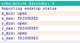
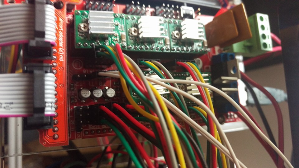
i attached pictures of what it does with the m119 code and my ramps set up picture. thanks so much for the reply!Quote
Mach
Quote
Zeegzeigler
Hey guys,I'm having a few issues. at the moment I just want to get printing so i can figure everything else thats wrong haha.
right now my x,z endstops do nothing,but light up also I cannot home. im new to the building aspect. I had a davinci,but wanted a more upgradable printer. here is my config i need help with. thank you in advance.
let me know if you need anything else.
CONFIG
Where do you have the endstops on your printer? To test your endstops, manually activate your endstops, and enter a m119 command into the g-code bar under the manual tab in repetier, this will tell you whether or not your endstops are actually triggering the proper signal pins. Usually if your endstops are not doing anything, that means that they are in the wrong spots on your ramps. Here is a picture where the endstops are supposed to go on the ramps based on where they are placed on the printer. Front, left, and bottom are the min positions on the printer, and back, right, and top are the max positions.
Depending on where your endstops are on your printer, you may need to inverse the homing direction for some axis, and comment or uncomment some of the defines under "#ifdef ENDSTOPPULLUPS". Also make sure that all of the values in repetier under "printer settings match up with your printer's configuration. Once you have your endstops working, you may need to reverse your stepper motor's connectors on the ramps, because they may turn in the wrong direction once everything is fixed wih yous endstops.

|
Re: Folger Tech 2020 i3 Printer Kit (Official Thread) January 20, 2016 01:36PM |
Registered: 8 years ago Posts: 15 |
Quote
Zeegzeigler
i attached pictures of what it does with the m119 code and my ramps set up picture. thanks so much for the reply!Quote
Mach
Quote
Zeegzeigler
Hey guys,I'm having a few issues. at the moment I just want to get printing so i can figure everything else thats wrong haha.
right now my x,z endstops do nothing,but light up also I cannot home. im new to the building aspect. I had a davinci,but wanted a more upgradable printer. here is my config i need help with. thank you in advance.
let me know if you need anything else.
CONFIG
Where do you have the endstops on your printer? To test your endstops, manually activate your endstops, and enter a m119 command into the g-code bar under the manual tab in repetier, this will tell you whether or not your endstops are actually triggering the proper signal pins. Usually if your endstops are not doing anything, that means that they are in the wrong spots on your ramps. Here is a picture where the endstops are supposed to go on the ramps based on where they are placed on the printer. Front, left, and bottom are the min positions on the printer, and back, right, and top are the max positions.
Depending on where your endstops are on your printer, you may need to inverse the homing direction for some axis, and comment or uncomment some of the defines under "#ifdef ENDSTOPPULLUPS". Also make sure that all of the values in repetier under "printer settings match up with your printer's configuration. Once you have your endstops working, you may need to reverse your stepper motor's connectors on the ramps, because they may turn in the wrong direction once everything is fixed wih yous endstops.
I posted my ramps set up and what the m119 code does. thanks so much for the reply!
|
Re: Folger Tech 2020 i3 Printer Kit (Official Thread) January 20, 2016 01:57PM |
Registered: 8 years ago Posts: 268 |
Quote
therippa
So I just ordered a BLTouch to replace my inductive sensor, would someone mind updating the wiki page with the basic instructions?
Done

My Stuff on Thingi
FolgerTech Wikia Page
Custom Search by Animoose
MakerSL.com
|
Re: Folger Tech 2020 i3 Printer Kit (Official Thread) January 20, 2016 02:00PM |
Registered: 8 years ago Posts: 15 |
Quote
Zeegzeigler
Quote
Zeegzeigler
i attached pictures of what it does with the m119 code and my ramps set up picture. thanks so much for the reply!Quote
Mach
Quote
Zeegzeigler
Hey guys,I'm having a few issues. at the moment I just want to get printing so i can figure everything else thats wrong haha.
right now my x,z endstops do nothing,but light up also I cannot home. im new to the building aspect. I had a davinci,but wanted a more upgradable printer. here is my config i need help with. thank you in advance.
let me know if you need anything else.
CONFIG
Where do you have the endstops on your printer? To test your endstops, manually activate your endstops, and enter a m119 command into the g-code bar under the manual tab in repetier, this will tell you whether or not your endstops are actually triggering the proper signal pins. Usually if your endstops are not doing anything, that means that they are in the wrong spots on your ramps. Here is a picture where the endstops are supposed to go on the ramps based on where they are placed on the printer. Front, left, and bottom are the min positions on the printer, and back, right, and top are the max positions.
Depending on where your endstops are on your printer, you may need to inverse the homing direction for some axis, and comment or uncomment some of the defines under "#ifdef ENDSTOPPULLUPS". Also make sure that all of the values in repetier under "printer settings match up with your printer's configuration. Once you have your endstops working, you may need to reverse your stepper motor's connectors on the ramps, because they may turn in the wrong direction once everything is fixed wih yous endstops.
I posted my ramps set up and what the m119 code does. thanks so much for the reply!
also my end stops are y(back of the printer) x is on the right side,which i have to move to the left side because when i home for the x it goes that way,i guess? lol. z is under the right motor. i put the end stops where the directions told me too. im new to this.
|
Re: Folger Tech 2020 i3 Printer Kit (Official Thread) January 20, 2016 02:06PM |
Registered: 8 years ago Posts: 268 |
Quote
Zeegzeigler
Quote
Zeegzeigler
Quote
Zeegzeigler
i attached pictures of what it does with the m119 code and my ramps set up picture. thanks so much for the reply!Quote
Mach
Quote
Zeegzeigler
Hey guys,I'm having a few issues. at the moment I just want to get printing so i can figure everything else thats wrong haha.
right now my x,z endstops do nothing,but light up also I cannot home. im new to the building aspect. I had a davinci,but wanted a more upgradable printer. here is my config i need help with. thank you in advance.
let me know if you need anything else.
CONFIG
Where do you have the endstops on your printer? To test your endstops, manually activate your endstops, and enter a m119 command into the g-code bar under the manual tab in repetier, this will tell you whether or not your endstops are actually triggering the proper signal pins. Usually if your endstops are not doing anything, that means that they are in the wrong spots on your ramps. Here is a picture where the endstops are supposed to go on the ramps based on where they are placed on the printer. Front, left, and bottom are the min positions on the printer, and back, right, and top are the max positions.
Depending on where your endstops are on your printer, you may need to inverse the homing direction for some axis, and comment or uncomment some of the defines under "#ifdef ENDSTOPPULLUPS". Also make sure that all of the values in repetier under "printer settings match up with your printer's configuration. Once you have your endstops working, you may need to reverse your stepper motor's connectors on the ramps, because they may turn in the wrong direction once everything is fixed wih yous endstops.
I posted my ramps set up and what the m119 code does. thanks so much for the reply!
also my end stops are y(back of the printer) x is on the right side,which i have to move to the left side because when i home for the x it goes that way,i guess? lol. z is under the right motor. i put the end stops where the directions told me too. im new to this.
Many people approach the X endstop location differently, I would suggest putting it on the left.
My Stuff on Thingi
FolgerTech Wikia Page
Custom Search by Animoose
MakerSL.com
|
Re: Folger Tech 2020 i3 Printer Kit (Official Thread) January 20, 2016 02:15PM |
Registered: 8 years ago Posts: 15 |
Also i have other issues like sometimes in manual mode it doesn't move a certain way until I home it,and slams into whichever way i send it end. even then sometimes it still wont move. also the nut for the z axis keeps coming out. i should kept my da vinci XD jk...sorta.
i would appreciate any help.
i would appreciate any help.
|
Re: Folger Tech 2020 i3 Printer Kit (Official Thread) January 20, 2016 02:27PM |
Registered: 8 years ago Posts: 13 |
Quote
sonnylowe
Quote
therippa
So I just ordered a BLTouch to replace my inductive sensor, would someone mind updating the wiki page with the basic instructions?
Done
Sweet! Hoping to see more of those missing upgraded to show up soon.
Need help? Visit the Folgertech Wikia Page
|
Re: Folger Tech 2020 i3 Printer Kit (Official Thread) January 20, 2016 02:47PM |
Registered: 8 years ago Posts: 314 |
|
Re: Folger Tech 2020 i3 Printer Kit (Official Thread) January 20, 2016 03:00PM |
Registered: 8 years ago Posts: 285 |
Quote
Zeegzeigler
Also i have other issues like sometimes in manual mode it doesn't move a certain way until I home it,and slams into whichever way i send it end. even then sometimes it still wont move. also the nut for the z axis keeps coming out. i should kept my da vinci XD jk...sorta.
i would appreciate any help.
To have your endstops in the back, right, and bottom, copy and paste this in place of your other endstop defines. I put some comment lines in to help understand some of the parts of the enstops config for you
// corse Endstop Settings
//#define ENDSTOPPULLUPS // Comment this out (using // at the start of the line) to disable the endstop pullup resistors
#ifndef ENDSTOPPULLUPS
// fine Enstop settings: Individual Pullups. will be ignord if ENDSTOPPULLUPS is defined
//#define ENDSTOPPULLUP_XMAX // Because you have your X endstop in the max position
// #define ENDSTOPPULLUP_YMAX // Because you have your Y endstop in the max position
#define ENDSTOPPULLUP_ZMAX // Because this is not being used
#define ENDSTOPPULLUP_XMIN // Because this is not being used
#define ENDSTOPPULLUP_YMIN // Because this is not being used
//#define ENDSTOPPULLUP_ZMIN // Because you have your Z endstop in the min position
#endif
#ifdef ENDSTOPPULLUPS // These are not used because the coarse endstop settings are not defined
// #define ENDSTOPPULLUP_XMAX
// #define ENDSTOPPULLUP_YMAX
// #define ENDSTOPPULLUP_ZMAX
#define ENDSTOPPULLUP_XMIN
#define ENDSTOPPULLUP_YMIN
#define ENDSTOPPULLUP_ZMIN
#endif
//----------------------------------------------------------------------------------------------------------------------------
Copy and paste this in place of home directions
/ ENDSTOP SETTINGS:
// Sets direction of endstops when homing; 1=MAX, -1=MIN
#define X_HOME_DIR 1 // Homes in the max direction
#define Y_HOME_DIR 1 // Homes in the max direction
#define Z_HOME_DIR -1 // Homes in the min direction
//--------------------------------------------------------------------------------
Move your X and Y endstop connector one place to the left on the ramps board. The printer will not move until you homes it. If the endstops are not setup properly, the printer will hit them, and then keep trying to move in that direction since it will never get the signal to stop. If you ever want to move your endstops, look at the comments I added in the configs above and that should give you a good idea what to uncomment and comment.
Folger Tech I3 2020 Wikia page: [folgertech.wikia.com]
Custom Folger Tech I3 2020 custom search
|
Re: Folger Tech 2020 i3 Printer Kit (Official Thread) January 20, 2016 03:01PM |
Registered: 8 years ago Posts: 93 |
Quote
UltiFix
Can anybody post a pic or put it on the wikia, of where the x endstop goes? Preferably a pic of were on the left?
Thanks!
Sam
I think this is the endstop mount I'm currently using: Left X-endstop mount for Folger Tech 2020 i3
There is a photo on the thing page:

Folger Tech 2020 i3 Wiki
Custom google search for the Folger Tech 2020 i3 forum topic by Animoose
My Thingiverse Designs
|
Re: Folger Tech 2020 i3 Printer Kit (Official Thread) January 20, 2016 03:15PM |
Registered: 8 years ago Posts: 15 |
Quote
Mach
Quote
Zeegzeigler
Also i have other issues like sometimes in manual mode it doesn't move a certain way until I home it,and slams into whichever way i send it end. even then sometimes it still wont move. also the nut for the z axis keeps coming out. i should kept my da vinci XD jk...sorta.
i would appreciate any help.
To have your endstops in the back, right, and bottom, copy and paste this in place of your other endstop defines. I put some comment lines in to help understand some of the parts of the enstops config for you
// corse Endstop Settings
//#define ENDSTOPPULLUPS // Comment this out (using // at the start of the line) to disable the endstop pullup resistors
#ifndef ENDSTOPPULLUPS
// fine Enstop settings: Individual Pullups. will be ignord if ENDSTOPPULLUPS is defined
//#define ENDSTOPPULLUP_XMAX // Because you have your X endstop in the max position
// #define ENDSTOPPULLUP_YMAX // Because you have your Y endstop in the max position
#define ENDSTOPPULLUP_ZMAX // Because this is not being used
#define ENDSTOPPULLUP_XMIN // Because this is not being used
#define ENDSTOPPULLUP_YMIN // Because this is not being used
//#define ENDSTOPPULLUP_ZMIN // Because you have your Z endstop in the min position
#endif
#ifdef ENDSTOPPULLUPS // These are not used because the coarse endstop settings are not defined
// #define ENDSTOPPULLUP_XMAX
// #define ENDSTOPPULLUP_YMAX
// #define ENDSTOPPULLUP_ZMAX
#define ENDSTOPPULLUP_XMIN
#define ENDSTOPPULLUP_YMIN
#define ENDSTOPPULLUP_ZMIN
#endif
//----------------------------------------------------------------------------------------------------------------------------
Copy and paste this in place of home directions
/ ENDSTOP SETTINGS:
// Sets direction of endstops when homing; 1=MAX, -1=MIN
#define X_HOME_DIR 1 // Homes in the max direction
#define Y_HOME_DIR 1 // Homes in the max direction
#define Z_HOME_DIR -1 // Homes in the min direction
//--------------------------------------------------------------------------------
Move your X and Y endstop connector one place to the left on the ramps board. The printer will not move until you homes it. If the endstops are not setup properly, the printer will hit them, and then keep trying to move in that direction since it will never get the signal to stop. If you ever want to move your endstops, look at the comments I added in the configs above and that should give you a good idea what to uncomment and comment.
thanks! so i do i just delete the old? i moved the end stops,ill have to do this part later hopefully works! thanks. is there a way to mount the x endstop on the left with the existing printed part? idont have acess to a printer right now. thanks!
|
Re: Folger Tech 2020 i3 Printer Kit (Official Thread) January 20, 2016 03:19PM |
Registered: 8 years ago Posts: 314 |
I don't have the printer kit yet, but I was looking at the instruction manual and the x endstop area was missing... Should I have my friend just print me up this mount and use it right away?Quote
Bert3D
Quote
UltiFix
Can anybody post a pic or put it on the wikia, of where the x endstop goes? Preferably a pic of were on the left?
Thanks!
Sam
I think this is the endstop mount I'm currently using: Left X-endstop mount for Folger Tech 2020 i3
There is a photo on the thing page:
|
Re: Folger Tech 2020 i3 Printer Kit (Official Thread) January 20, 2016 03:23PM |
Registered: 8 years ago Posts: 131 |
Quote
UltiFix
I don't have the printer kit yet, but I was looking at the instruction manual and the x endstop area was missing... Should I have my friend just print me up this mount and use it right away?Quote
Bert3D
Quote
UltiFix
Can anybody post a pic or put it on the wikia, of where the x endstop goes? Preferably a pic of were on the left?
Thanks!
Sam
I think this is the endstop mount I'm currently using: Left X-endstop mount for Folger Tech 2020 i3
There is a photo on the thing page:
Not home to take a picture but I was able to mount the x-axis stop on the left with the stock parts. Just have it hit the extruder motor.
|
Re: Folger Tech 2020 i3 Printer Kit (Official Thread) January 20, 2016 03:29PM |
Registered: 8 years ago Posts: 285 |
Quote
Zeegzeigler
Quote
Mach
Quote
Zeegzeigler
Also i have other issues like sometimes in manual mode it doesn't move a certain way until I home it,and slams into whichever way i send it end. even then sometimes it still wont move. also the nut for the z axis keeps coming out. i should kept my da vinci XD jk...sorta.
i would appreciate any help.
To have your endstops in the back, right, and bottom, copy and paste this in place of your other endstop defines. I put some comment lines in to help understand some of the parts of the enstops config for you
// corse Endstop Settings
//#define ENDSTOPPULLUPS // Comment this out (using // at the start of the line) to disable the endstop pullup resistors
#ifndef ENDSTOPPULLUPS
// fine Enstop settings: Individual Pullups. will be ignord if ENDSTOPPULLUPS is defined
//#define ENDSTOPPULLUP_XMAX // Because you have your X endstop in the max position
// #define ENDSTOPPULLUP_YMAX // Because you have your Y endstop in the max position
#define ENDSTOPPULLUP_ZMAX // Because this is not being used
#define ENDSTOPPULLUP_XMIN // Because this is not being used
#define ENDSTOPPULLUP_YMIN // Because this is not being used
//#define ENDSTOPPULLUP_ZMIN // Because you have your Z endstop in the min position
#endif
#ifdef ENDSTOPPULLUPS // These are not used because the coarse endstop settings are not defined
// #define ENDSTOPPULLUP_XMAX
// #define ENDSTOPPULLUP_YMAX
// #define ENDSTOPPULLUP_ZMAX
#define ENDSTOPPULLUP_XMIN
#define ENDSTOPPULLUP_YMIN
#define ENDSTOPPULLUP_ZMIN
#endif
//----------------------------------------------------------------------------------------------------------------------------
Copy and paste this in place of home directions
/ ENDSTOP SETTINGS:
// Sets direction of endstops when homing; 1=MAX, -1=MIN
#define X_HOME_DIR 1 // Homes in the max direction
#define Y_HOME_DIR 1 // Homes in the max direction
#define Z_HOME_DIR -1 // Homes in the min direction
//--------------------------------------------------------------------------------
Move your X and Y endstop connector one place to the left on the ramps board. The printer will not move until you homes it. If the endstops are not setup properly, the printer will hit them, and then keep trying to move in that direction since it will never get the signal to stop. If you ever want to move your endstops, look at the comments I added in the configs above and that should give you a good idea what to uncomment and comment.
thanks! so i do i just delete the old? i moved the end stops,ill have to do this part later hopefully works! thanks. is there a way to mount the x endstop on the left with the existing printed part? idont have acess to a printer right now. thanks!
The above configs are just segments of the endstop config section, so they replace of the configs that look similar to them, not the entire endstop section. You should be able to put the endstop holder that comes with the printer on the left until you can print a better one. Just keep in mind that the above config will have to be changed to match the printer if you put it on the left since it is set to be on the right.
Folger Tech I3 2020 Wikia page: [folgertech.wikia.com]
Custom Folger Tech I3 2020 custom search
|
Re: Folger Tech 2020 i3 Printer Kit (Official Thread) January 20, 2016 03:29PM |
Registered: 8 years ago Posts: 93 |
Quote
UltiFix
I don't have the printer kit yet, but I was looking at the instruction manual and the x endstop area was missing... Should I have my friend just print me up this mount and use it right away?Quote
Bert3D
Quote
UltiFix
Can anybody post a pic or put it on the wikia, of where the x endstop goes? Preferably a pic of were on the left?
Thanks!
Sam
I think this is the endstop mount I'm currently using: Left X-endstop mount for Folger Tech 2020 i3
I would. I had mine on the right forever, but for autolevel to work, I had to move it to the left. On most printers it is on the left (min X, X=0), and things just seem to work better with the endstops at min instead of max. Autolevel, at least in the current versions of Marlin, is broken if the X-endstop isn't at the zero/min position (ie on the left.)
Since few if any of the Marlin firmware developers and debuggers have a printer with the x endstop at max, the code isn't tested well in that configuration.
There is really no good reason to have it on the right, except maybe keeping the wires all on one side. You can still run the wire neatly to the left, so this isn't much of a reason to have it on the right..
Edited 1 time(s). Last edit at 01/20/2016 03:30PM by Bert3D.
Folger Tech 2020 i3 Wiki
Custom google search for the Folger Tech 2020 i3 forum topic by Animoose
My Thingiverse Designs
|
Re: Folger Tech 2020 i3 Printer Kit (Official Thread) January 20, 2016 03:34PM |
Registered: 8 years ago Posts: 93 |
Quote
marc2912
Not home to take a picture but I was able to mount the x-axis stop on the left with the stock parts. Just have it hit the extruder motor.
Very good point. The stock mount should work just as well on the left as on the right. I wasn't using the stock one when I had it on the right either. I switched from the stock one because I didn't like they way it made it stick out, getting bumped all the time..
Folger Tech 2020 i3 Wiki
Custom google search for the Folger Tech 2020 i3 forum topic by Animoose
My Thingiverse Designs
|
Re: Folger Tech 2020 i3 Printer Kit (Official Thread) January 20, 2016 03:36PM |
Registered: 8 years ago Posts: 15 |
Quote
Mach
Quote
Zeegzeigler
Quote
Mach
Quote
Zeegzeigler
Also i have other issues like sometimes in manual mode it doesn't move a certain way until I home it,and slams into whichever way i send it end. even then sometimes it still wont move. also the nut for the z axis keeps coming out. i should kept my da vinci XD jk...sorta.
i would appreciate any help.
To have your endstops in the back, right, and bottom, copy and paste this in place of your other endstop defines. I put some comment lines in to help understand some of the parts of the enstops config for you
// corse Endstop Settings
//#define ENDSTOPPULLUPS // Comment this out (using // at the start of the line) to disable the endstop pullup resistors
#ifndef ENDSTOPPULLUPS
// fine Enstop settings: Individual Pullups. will be ignord if ENDSTOPPULLUPS is defined
//#define ENDSTOPPULLUP_XMAX // Because you have your X endstop in the max position
// #define ENDSTOPPULLUP_YMAX // Because you have your Y endstop in the max position
#define ENDSTOPPULLUP_ZMAX // Because this is not being used
#define ENDSTOPPULLUP_XMIN // Because this is not being used
#define ENDSTOPPULLUP_YMIN // Because this is not being used
//#define ENDSTOPPULLUP_ZMIN // Because you have your Z endstop in the min position
#endif
#ifdef ENDSTOPPULLUPS // These are not used because the coarse endstop settings are not defined
// #define ENDSTOPPULLUP_XMAX
// #define ENDSTOPPULLUP_YMAX
// #define ENDSTOPPULLUP_ZMAX
#define ENDSTOPPULLUP_XMIN
#define ENDSTOPPULLUP_YMIN
#define ENDSTOPPULLUP_ZMIN
#endif
//----------------------------------------------------------------------------------------------------------------------------
Copy and paste this in place of home directions
/ ENDSTOP SETTINGS:
// Sets direction of endstops when homing; 1=MAX, -1=MIN
#define X_HOME_DIR 1 // Homes in the max direction
#define Y_HOME_DIR 1 // Homes in the max direction
#define Z_HOME_DIR -1 // Homes in the min direction
//--------------------------------------------------------------------------------
Move your X and Y endstop connector one place to the left on the ramps board. The printer will not move until you homes it. If the endstops are not setup properly, the printer will hit them, and then keep trying to move in that direction since it will never get the signal to stop. If you ever want to move your endstops, look at the comments I added in the configs above and that should give you a good idea what to uncomment and comment.
thanks! so i do i just delete the old? i moved the end stops,ill have to do this part later hopefully works! thanks. is there a way to mount the x endstop on the left with the existing printed part? idont have acess to a printer right now. thanks!
The above configs are just segments of the endstop config section, so they replace of the configs that look similar to them, not the entire endstop section. You should be able to put the endstop holder that comes with the printer on the left until you can print a better one. Just keep in mind that the above config will have to be changed to match the printer if you put it on the left since it is set to be on the right.
thanks! ill keep in on the right for now,but for some reason the end stops still dont work. i moved them a,ll to the left 1 slot. so they are in 1,3 and 5. also the y home moved to the front of the printer,is that correct? ill see if i can start to understand what the configs mean lol. i really appreciate the help.
|
Re: Folger Tech 2020 i3 Printer Kit (Official Thread) January 20, 2016 03:41PM |
Registered: 8 years ago Posts: 51 |
Quote
sonnylowe
Quote
therippa
So I just ordered a BLTouch to replace my inductive sensor, would someone mind updating the wiki page with the basic instructions?
Done
Are they that much better than inductive sensors? Just wondering it its worth getting one. I have an inductive on the way, but if its better I'll keep the inductive as a spare.
|
Re: Folger Tech 2020 i3 Printer Kit (Official Thread) January 20, 2016 03:44PM |
Registered: 8 years ago Posts: 285 |
Quote
Zeegzeigler
Quote
Mach
Quote
Zeegzeigler
[qoute=Mach]
Quote
Zeegzeigler
Move your X and Y endstop connector one place to the left on the ramps board. The printer will not move until you homes it. If the endstops are not setup properly, the printer will hit them, and then keep trying to move in that direction since it will never get the signal to stop. If you ever want to move your endstops, look at the comments I added in the configs above and that should give you a good idea what to uncomment and comment.
thanks! so i do i just delete the old? i moved the end stops,ill have to do this part later hopefully works! thanks. is there a way to mount the x endstop on the left with the existing printed part? idont have acess to a printer right now. thanks!
The above configs are just segments of the endstop config section, so they replace of the configs that look similar to them, not the entire endstop section. You should be able to put the endstop holder that comes with the printer on the left until you can print a better one. Just keep in mind that the above config will have to be changed to match the printer if you put it on the left since it is set to be on the right.
thanks! ill keep in on the right for now,but for some reason the end stops still dont work. i moved them a,ll to the left 1 slot. so they are in 1,3 and 5. also the y home moved to the front of the printer,is that correct? ill see if i can start to understand what the configs mean lol. i really appreciate the help.
Move only the X and Y connectors if you want the Z to home to the bottom. If the Y endstop is in the back, but the bed moves to the front, just reverse the Y motor connector on the ramps.
Edited 1 time(s). Last edit at 01/20/2016 03:53PM by Mach.
Folger Tech I3 2020 Wikia page: [folgertech.wikia.com]
Custom Folger Tech I3 2020 custom search
|
Re: Folger Tech 2020 i3 Printer Kit (Official Thread) January 20, 2016 03:50PM |
Registered: 8 years ago Posts: 314 |
Anything else that I should have my friend print for me while hes printing the endstop thing? Otherwise im sure i will be printing my self a crapload of stuff once it's up and running.Quote
Bert3D
Quote
UltiFix
I don't have the printer kit yet, but I was looking at the instruction manual and the x endstop area was missing... Should I have my friend just print me up this mount and use it right away?Quote
Bert3D
Quote
UltiFix
Can anybody post a pic or put it on the wikia, of where the x endstop goes? Preferably a pic of were on the left?
Thanks!
Sam
I think this is the endstop mount I'm currently using: Left X-endstop mount for Folger Tech 2020 i3
I would. I had mine on the right forever, but for autolevel to work, I had to move it to the left. On most printers it is on the left (min X, X=0), and things just seem to work better with the endstops at min instead of max. Autolevel, at least in the current versions of Marlin, is broken if the X-endstop isn't at the zero/min position (ie on the left.)
Since few if any of the Marlin firmware developers and debuggers have a printer with the x endstop at max, the code isn't tested well in that configuration.
There is really no good reason to have it on the right, except maybe keeping the wires all on one side. You can still run the wire neatly to the left, so this isn't much of a reason to have it on the right..
|
Re: Folger Tech 2020 i3 Printer Kit (Official Thread) January 20, 2016 03:51PM |
Registered: 8 years ago Posts: 93 |
Quote
peeejayz
Quote
sonnylowe
Quote
therippa
So I just ordered a BLTouch to replace my inductive sensor, would someone mind updating the wiki page with the basic instructions?
Done
Are they that much better than inductive sensors? Just wondering it its worth getting one. I have an inductive on the way, but if its better I'll keep the inductive as a spare.
That's what I was wondering as well. I have a BLTouch on the way, and I'm sure it is better than the servo setup I'm using now, and should be easier than the switch to an aluminum print bed to make an inductive sensor work.
If you have a working inductive sensor setup, the only advantage I can see would be that it measures to the top of the surface, where the inductive sensor measures to the metal plate. That means you need to insure whatever you put on top of the metal plate is always the same thickness. That's probably not really a huge limitation, but one time I accidentally put my glass plate on top of one of the corner screw heads, and because the autolevel probed it and just adjusted, I didn't even notice it wasn't flat. Prints worked fine anyway. If it was sensing the bed underneath, that would have been a problem.
I haven't gotten my BLTouch, or tried an inductive setup, so I'd love to hear from others how they have worked for them.
Edited 1 time(s). Last edit at 01/20/2016 03:55PM by Bert3D.
Folger Tech 2020 i3 Wiki
Custom google search for the Folger Tech 2020 i3 forum topic by Animoose
My Thingiverse Designs
|
Re: Folger Tech 2020 i3 Printer Kit (Official Thread) January 20, 2016 03:57PM |
Registered: 8 years ago Posts: 314 |
So let me get this straight, there are 2 kinds of autolevel, one were this are servos moving the bed, and the other is a sensor and the z axis just moves up and down to compensate for bed level changes, im assuming the second choice is cheaper. Right? What are most of you guys doing?Quote
Bert3D
Quote
peeejayz
Quote
sonnylowe
Quote
therippa
So I just ordered a BLTouch to replace my inductive sensor, would someone mind updating the wiki page with the basic instructions?
Done
Are they that much better than inductive sensors? Just wondering it its worth getting one. I have an inductive on the way, but if its better I'll keep the inductive as a spare.
That's what I was wondering as well. I have a BLTouch on the way, and I'm sure it is better than the servo setup I'm using now, and should be easier than the switch to an aluminum print bed to make an inductive sensor work.
If you have a working inductive sensor setup, the only advantage I can see would be that it measures to the top of the surface, where the inductive sensor measures to the metal plate. That means you need to insure whatever you put on top of the metal plate is always the same thickness. That's probably not really a huge limitation, but one time I accidentally put my glass plate on top of one of the corner screw heads, and because the autolevel probed it and just adjusted, I didn't even notice it wasn't flat. Prints worked fine anyway. If it was sensing the bed underneath, that would have been a problem.
I haven't gotten my BLTouch, or tried an inductive setup, so I'd love to hear from others how they have worked for them.
|
Re: Folger Tech 2020 i3 Printer Kit (Official Thread) January 20, 2016 04:09PM |
Registered: 8 years ago Posts: 285 |
Quote
UltiFix
So let me get this straight, there are 2 kinds of autolevel, one were this are servos moving the bed, and the other is a sensor and the z axis just moves up and down to compensate for bed level changes, im assuming the second choice is cheaper. Right? What are most of you guys doing?Quote
Bert3D
Quote
peeejayz
Quote
sonnylowe
Quote
therippa
So I just ordered a BLTouch to replace my inductive sensor, would someone mind updating the wiki page with the basic instructions?
Done
Are they that much better than inductive sensors? Just wondering it its worth getting one. I have an inductive on the way, but if its better I'll keep the inductive as a spare.
That's what I was wondering as well. I have a BLTouch on the way, and I'm sure it is better than the servo setup I'm using now, and should be easier than the switch to an aluminum print bed to make an inductive sensor work.
If you have a working inductive sensor setup, the only advantage I can see would be that it measures to the top of the surface, where the inductive sensor measures to the metal plate. That means you need to insure whatever you put on top of the metal plate is always the same thickness. That's probably not really a huge limitation, but one time I accidentally put my glass plate on top of one of the corner screw heads, and because the autolevel probed it and just adjusted, I didn't even notice it wasn't flat. Prints worked fine anyway. If it was sensing the bed underneath, that would have been a problem.
I haven't gotten my BLTouch, or tried an inductive setup, so I'd love to hear from others how they have worked for them.
The servo is not used to move the bed. It is used in a similar way that the sensor is used. The servo has a arm attached to it, which has a switch on the end of it. The servo swings the arm and switch down, and then the Z axis moves down to touch the bed until the switch is activated. I use the sensor method, but not for ABL.
Folger Tech I3 2020 Wikia page: [folgertech.wikia.com]
Custom Folger Tech I3 2020 custom search
|
Re: Folger Tech 2020 i3 Printer Kit (Official Thread) January 20, 2016 04:11PM |
Registered: 8 years ago Posts: 314 |
What would you reccomend I use? The servo with a bumper switch, or the sensor thingy? Thanks for clarifying to! Im new to this obviosulyQuote
Mach
Quote
UltiFix
So let me get this straight, there are 2 kinds of autolevel, one were this are servos moving the bed, and the other is a sensor and the z axis just moves up and down to compensate for bed level changes, im assuming the second choice is cheaper. Right? What are most of you guys doing?Quote
Bert3D
Quote
peeejayz
Quote
sonnylowe
Quote
therippa
So I just ordered a BLTouch to replace my inductive sensor, would someone mind updating the wiki page with the basic instructions?
Done
Are they that much better than inductive sensors? Just wondering it its worth getting one. I have an inductive on the way, but if its better I'll keep the inductive as a spare.
That's what I was wondering as well. I have a BLTouch on the way, and I'm sure it is better than the servo setup I'm using now, and should be easier than the switch to an aluminum print bed to make an inductive sensor work.
If you have a working inductive sensor setup, the only advantage I can see would be that it measures to the top of the surface, where the inductive sensor measures to the metal plate. That means you need to insure whatever you put on top of the metal plate is always the same thickness. That's probably not really a huge limitation, but one time I accidentally put my glass plate on top of one of the corner screw heads, and because the autolevel probed it and just adjusted, I didn't even notice it wasn't flat. Prints worked fine anyway. If it was sensing the bed underneath, that would have been a problem.
I haven't gotten my BLTouch, or tried an inductive setup, so I'd love to hear from others how they have worked for them.
The servo is not used to move the bed. It is used in a similar way that the sensor is used. The servo has a arm attached to it, which has a switch on the end of it. The servo swings the arm and switch down, and then the Z axis moves down to touch the bed until the switch is activated. I use the sensor method, but not for ABL.
|
Re: Folger Tech 2020 i3 Printer Kit (Official Thread) January 20, 2016 04:13PM |
Registered: 8 years ago Posts: 93 |
Quote
UltiFix
So let me get this straight, there are 2 kinds of autolevel, one were this are servos moving the bed, and the other is a sensor and the z axis just moves up and down to compensate for bed level changes, im assuming the second choice is cheaper. Right? What are most of you guys doing?
No, the servo method has a servo mounted on the print head, with an arm attached and an endstop type switch on the end of the arm. When it is time to home Z, or probe, the servo arm swings down and the head lowers until the switch closes. When the probing is done, the servo arm goes up, so the switch is out of the way, and the head can go on down to print.
I don't have a good photo, but you can see it in this one:

Folger Tech 2020 i3 Wiki
Custom google search for the Folger Tech 2020 i3 forum topic by Animoose
My Thingiverse Designs
|
Re: Folger Tech 2020 i3 Printer Kit (Official Thread) January 20, 2016 04:17PM |
Registered: 8 years ago Posts: 26 |
I have a question regarding printing. Still waiting on parts to get this going. My question is this. I have read where people will set their firmware to print at 0.1mm or 0.2mm for better quality. The printer comes with a 0.4mm extruder tip, does this need to be changed to a smaller opening to facilitate printing thinner layers?
Thanks, Jim
Thanks, Jim
|
Re: Folger Tech 2020 i3 Printer Kit (Official Thread) January 20, 2016 04:17PM |
Registered: 8 years ago Posts: 268 |
Quote
UltiFix
So let me get this straight, there are 2 kinds of autolevel, one were this are servos moving the bed, and the other is a sensor and the z axis just moves up and down to compensate for bed level changes, im assuming the second choice is cheaper. Right? What are most of you guys doing?Quote
Bert3D
Quote
peeejayz
Quote
sonnylowe
Quote
therippa
So I just ordered a BLTouch to replace my inductive sensor, would someone mind updating the wiki page with the basic instructions?
Done
Are they that much better than inductive sensors? Just wondering it its worth getting one. I have an inductive on the way, but if its better I'll keep the inductive as a spare.
That's what I was wondering as well. I have a BLTouch on the way, and I'm sure it is better than the servo setup I'm using now, and should be easier than the switch to an aluminum print bed to make an inductive sensor work.
If you have a working inductive sensor setup, the only advantage I can see would be that it measures to the top of the surface, where the inductive sensor measures to the metal plate. That means you need to insure whatever you put on top of the metal plate is always the same thickness. That's probably not really a huge limitation, but one time I accidentally put my glass plate on top of one of the corner screw heads, and because the autolevel probed it and just adjusted, I didn't even notice it wasn't flat. Prints worked fine anyway. If it was sensing the bed underneath, that would have been a problem.
I haven't gotten my BLTouch, or tried an inductive setup, so I'd love to hear from others how they have worked for them.
They both work exactly the same, they just use different means to check the levelness of the bed. Either way the Z motor make the adjustment while printing.
The BLtouch and Servo/Micro Switch Setup work by actually touching the surface you are printing on. An Inductive Proximity Sensor measure how close you are to a metallic surface without actually touching it. A Capacitive Sensor measure density changes in almost anything, so it can read the glass, BuildTak, or possibly the Kapton Tape surface, otherwise it works just like the Inductive Sensor. If you look through the thread you will find lots of info and lots of opinions on both.
As far as cost, the Inductive Sensor and BLtouch cost about the same if you buy an aluminum build plate. If you can find the Capacitive Sensor I suggested earlier it can be as little as $15.00 with no need to buy any other build plate material.
There is success with all three setups, every person running them likes their choice for one reason or another, they all do the basically the same thing, it's really just your preference...
My Stuff on Thingi
FolgerTech Wikia Page
Custom Search by Animoose
MakerSL.com


Sorry, only registered users may post in this forum.