New P3Steel build
Posted by onekk
|
New P3Steel build June 22, 2017 08:20AM |
Registered: 6 years ago Posts: 1,059 |
Hi to all, I'm approaching to the RepRap World, so I wish to discuss with you my build.
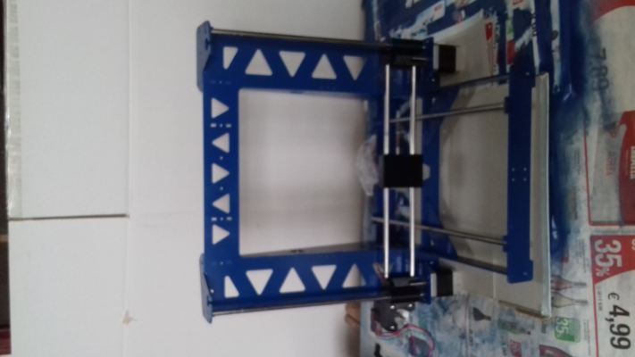
The first assembling test, only to test the proper frame alignment.
The frame I've bought from a Lithuanian seller, and has a Z top plate somewhat different from those I've seen on the net.
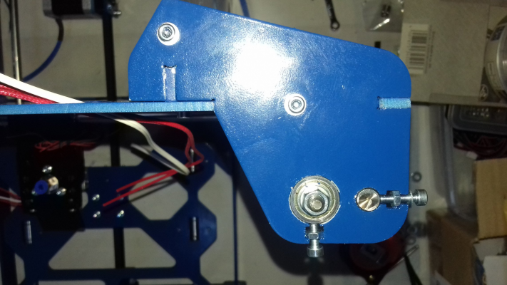
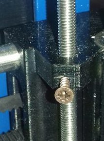
This is a zooming of the part, I will make a support for the 625ZZ bearing to suspend the Z threaded rods as a rod that is "pulled" is more stable than a rod pushed (try to push a rod and it will bend)
Some wiring done I've managed to get some blue wiring protection, I have to made some extender from the RAMPS to homemade breadboard with screw terminals.
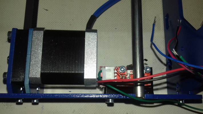
This is the first problem with the building, my motor is a 48 mm one and the Toolson Y endstop support is not adeguate as it position the endstop wires too near the back of the motor, this is probably one of the first part that I've to print when the printer is ready.
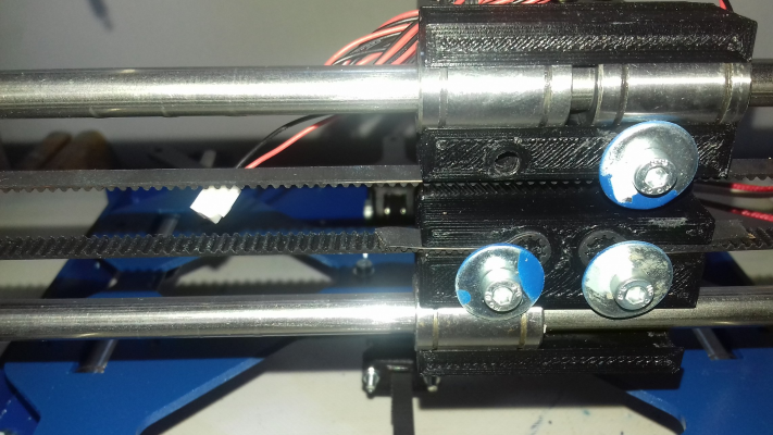
The back of the X carriage, it lacks of an LM8UU that is defective so I've ordered some replacements.
The lower washers mantains in place the belts, the uppers probably have to be changed with some smaller ones.
For now it all stay tuned, as I've some hints to ask and some modification to show.
|
Re: New P3Steel build March 24, 2018 04:05AM |
Registered: 6 years ago Posts: 1,059 |
A little advance was made, the machine is assembled and somewhat tested.
I have found that the bearing on the top are F625ZZ (with a little flange) but sadly the threaded rods are a little short.
I have "tested" the machine, but during the initial setup phase some went wrong and I fried the Arduino Mega (hope not the new DRV8825 drivers I have just purchased).
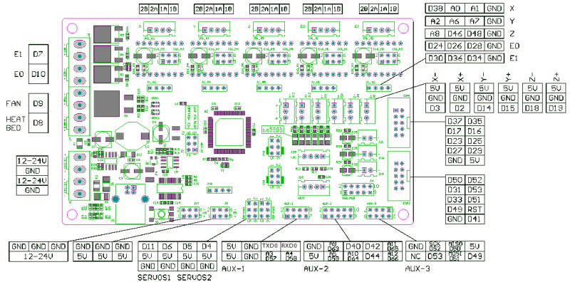
I have ordered an MKS GEN v1.2 board, hope that it is more compact and with better thermal performaces than the Arduino Mega + Ramps 1.4, on paper (and photos) it seem that the MOSFET are three IRLB8473 and one much bigger for the heatbed, (it has a configuration of D7 = H0 D10 =H1 D9 = FAN D8 = BED) but i think i will reuse the external "Gen 7 MOSFET" to mantain some thermal separation, as I've noted that most of the failure are generally cused by the Heatbed MOSFET becoming HOT (10 or more Ampere DC) or by some failures in the screw terminal connections causing them to heat and burn.
The goal is to achieve a somewhat roughness wiring all the 12V positives separately and relying on automotive fuses on the lines (5A for the Hotend and 10/15A for the hotend) and using only the negative connections on the board.
I plan to drive the two Hotend fans through two spare pins on AUX1 (D57 and D58) with a RRD board mountend with a small riser to use "non standard" pins, the RRD is meant to be used on the servo output but these are "needed" by some other hardware I have planned to implement in future.
For the HotBed and the Controller fan i plan to utilize two other spare pins (D59 and D64) on AUX2, the controller is driven by an IRF520 chinese boards and plan to use them to drive like in the RAMPS setup.
Now I'm waiting for the material I have purchased online to implement the new electronics and in the meantime I will rewire the machine for using the new electronics.
|
Re: New P3Steel build April 08, 2018 06:34AM |
Registered: 6 years ago Posts: 1,059 |
| Photo | Description |
|---|---|
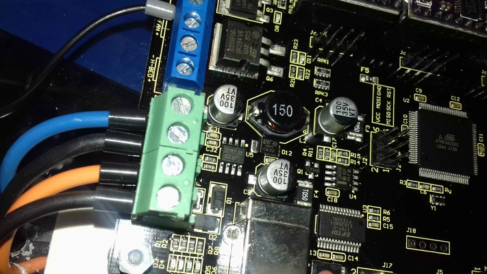
| A little close up of the electronics with the power regulator and the ftdi communication chip. | |
| A general view of the control board it's a MKS GEN v1.2 (very cheap, around 25 Euro) BELOW: there is the Sevenswitch MOSFET borad (the light brown one) and the 5v fly down regulator. |
|
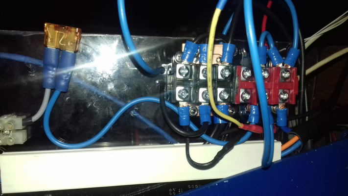
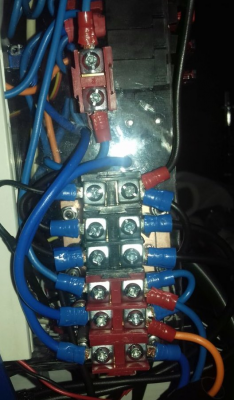
| A view of the electric connession block for ring or spade connectors. LEFT: the 5A automotive fuse that bring the 12V positive to the H0 HotEnd, This is done on pourpose, as not passing the 12V positive power to the board fuse, doing so if some went wrong the automotive fuse blow and you can replace it an see what element is the culprit. |
|
| A view of the fuse holders for the fans, the automotive fuses are too big to protect the fans that absorb 0.1 - 0.2 A max each, i have used 300mA fuse, LEFT: Screw connectors for E0 E1 and X axis. RIGHT: "RRD fan extender" that drives the two extruder fans using "AUX 1" pins 57 and 58 BELOW: Red wire that exit from the screw teminal bring the 12V through an automotive fuse to the H0 HotEnd, that you see in the preceding image |
More to come ....
Edited 3 time(s). Last edit at 04/09/2018 06:09PM by onekk.
P3Steel - MKS GEN v1.2 e REPRAP_DISCOUNT_FULL_GRAPHIC_SMART_CONTROLLER + Gen 7 MOSFET (HotBed) + alimentatore step-down 12V -> 5V
Firmware MK4duo 4.3.6 con ABL induttivo con LJ18A3 - Slic3R (Originale) ed ESP3D per controllare la stampante da remoto.
HotEnd Cinese V6 clone con ugello da 0.4mm.
[My Building Log]
|
Re: New P3Steel build April 10, 2018 01:03PM |
Registered: 6 years ago Posts: 1,059 |
The printer is assembled and even the WiFI using a cheap ESP-12E with this firmware loaded ESP3D is working, one minor glitch is the wrong communication pin assignement connection now some testing and then some printing.
It's a very good sensation to control the 3D printer from a computer with wifi (maybe i will search for a android app to use and old tablet to make a control display)
Edited 1 time(s). Last edit at 04/10/2018 01:14PM by onekk.
P3Steel - MKS GEN v1.2 e REPRAP_DISCOUNT_FULL_GRAPHIC_SMART_CONTROLLER + Gen 7 MOSFET (HotBed) + alimentatore step-down 12V -> 5V
Firmware MK4duo 4.3.6 con ABL induttivo con LJ18A3 - Slic3R (Originale) ed ESP3D per controllare la stampante da remoto.
HotEnd Cinese V6 clone con ugello da 0.4mm.
[My Building Log]
| Photo | Description |
|---|---|
| The IP adress shown on the display | |
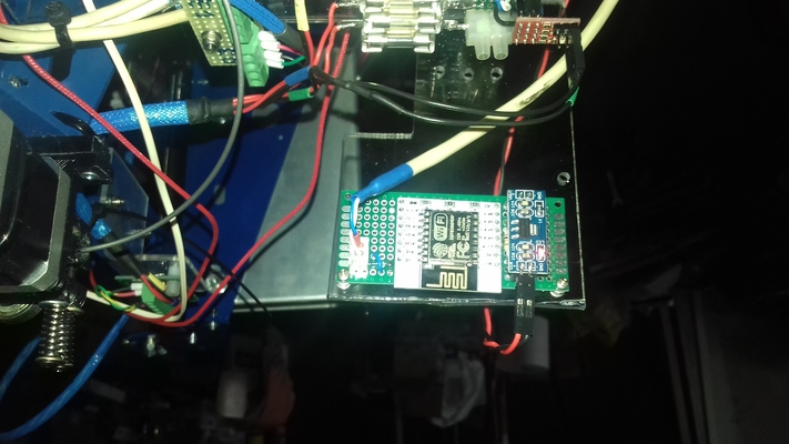
| The Breadborad with the ESP-12E, a 5v to 3.3V converter and 4 10K resistors, two 220uF condenser, 1 1n4148 diode for the shift level conversion on RX pin of the ESP-12E, and a push button for the reset of the ESP-12E | |
| The connession on AUX 1, blue wire on row 2is the TX pin, white wire on row 2 is the RX pin of the ESP-12E |
It's a very good sensation to control the 3D printer from a computer with wifi (maybe i will search for a android app to use and old tablet to make a control display)
Edited 1 time(s). Last edit at 04/10/2018 01:14PM by onekk.
P3Steel - MKS GEN v1.2 e REPRAP_DISCOUNT_FULL_GRAPHIC_SMART_CONTROLLER + Gen 7 MOSFET (HotBed) + alimentatore step-down 12V -> 5V
Firmware MK4duo 4.3.6 con ABL induttivo con LJ18A3 - Slic3R (Originale) ed ESP3D per controllare la stampante da remoto.
HotEnd Cinese V6 clone con ugello da 0.4mm.
[My Building Log]
|
Re: New P3Steel build April 10, 2018 04:05PM |
Registered: 10 years ago Posts: 14,672 |
How fast can you upload files to it over WiFi?
Large delta printer [miscsolutions.wordpress.com], E3D tool changer, Robotdigg SCARA printer, Crane Quad and Ormerod
Disclosure: I design Duet electronics and work on RepRapFirmware, [duet3d.com].
Large delta printer [miscsolutions.wordpress.com], E3D tool changer, Robotdigg SCARA printer, Crane Quad and Ormerod
Disclosure: I design Duet electronics and work on RepRapFirmware, [duet3d.com].
|
Re: New P3Steel build April 25, 2018 10:03AM |
Registered: 6 years ago Posts: 1,059 |
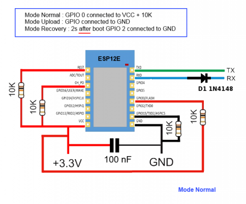
Here the schematics of the ESP12E modified with the inverse diode clamping trick
Here the schematics of the MKS BASE V1.2 modified with the correct pin assignement.
The MKS BASE pins are the correct pin so RX0 and TX0 are the RX0 and TX0 pin of the Atmega 2560 the same where the FTDI chip is connected.
To wire the ESP12E module you have to connect the ESP12E RX pin to the TX pin of the board and the ESP12E TX pin to the RX pin of the board.
The diode trick work in this manner, when the atmega send a LOW signal it pull to the GND the TX pin, the ESP12E has an internal pullup resistor and the 3.3V goes to the GND trough the diode and the ESP12E receive a LOW signal, when the atmega is sending a 5V to the diode, (HIGH) the 3.3V can't flow to nowhere as the atmega side is at a much higher voltage than the 3.3V and the diode is not conducting, so the ESP12E reads a HIGH signal.
The ESP12E TX level is enough to trigger a HIGH signal to the atmega RX port, so no problem here.
Regards
Carlo D.
Edited 1 time(s). Last edit at 04/25/2018 10:03AM by onekk.
P3Steel - MKS GEN v1.2 e REPRAP_DISCOUNT_FULL_GRAPHIC_SMART_CONTROLLER + Gen 7 MOSFET (HotBed) + alimentatore step-down 12V -> 5V
Firmware MK4duo 4.3.6 con ABL induttivo con LJ18A3 - Slic3R (Originale) ed ESP3D per controllare la stampante da remoto.
HotEnd Cinese V6 clone con ugello da 0.4mm.
[My Building Log]
|
Re: New P3Steel build May 31, 2018 12:30PM |
Registered: 6 years ago Posts: 1,059 |
Some improvement done, (image to come)
Regards
Carlo D.
Edited 1 time(s). Last edit at 06/02/2018 10:29AM by onekk.
P3Steel - MKS GEN v1.2 e REPRAP_DISCOUNT_FULL_GRAPHIC_SMART_CONTROLLER + Gen 7 MOSFET (HotBed) + alimentatore step-down 12V -> 5V
Firmware MK4duo 4.3.6 con ABL induttivo con LJ18A3 - Slic3R (Originale) ed ESP3D per controllare la stampante da remoto.
HotEnd Cinese V6 clone con ugello da 0.4mm.
[My Building Log]
| Photo | Description |
|---|---|
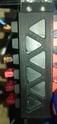
| New fuse holder. Stackable Automotive type, very cheap 0.50 Euro each. New printed fuse holder mount, with a p3steel look, this was the first ABS printing test, it was not too bad, but it is not perfect, maybe some tweking in the Slic3r setting are needed, but apart from the ahestethic is very strong (Spanish ABS-HI). |
|
| Installed a capacitive probe for ABL 18mm one. Powered at 12V and with same diode hack used to achieve level conversion for the ESP12E. |
|
| New placement of power wirings. | |
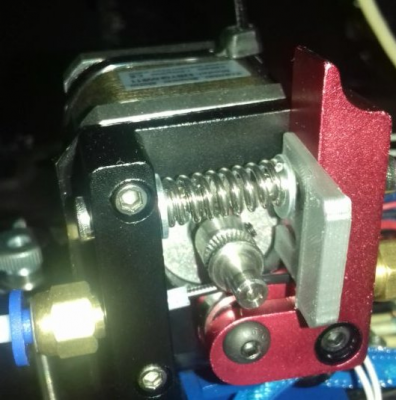
| New extruder. It is a cheap chinese one modified replacing the gear with MK8 type, new plain bearing and a less stronger spring. |
|
| Installed a retainer screw on the Z axis nylon nuts. Otherwise the nylon nut tends to slips off the hole. |
Regards
Carlo D.
Edited 1 time(s). Last edit at 06/02/2018 10:29AM by onekk.
P3Steel - MKS GEN v1.2 e REPRAP_DISCOUNT_FULL_GRAPHIC_SMART_CONTROLLER + Gen 7 MOSFET (HotBed) + alimentatore step-down 12V -> 5V
Firmware MK4duo 4.3.6 con ABL induttivo con LJ18A3 - Slic3R (Originale) ed ESP3D per controllare la stampante da remoto.
HotEnd Cinese V6 clone con ugello da 0.4mm.
[My Building Log]
Sorry, only registered users may post in this forum.
