EinsyRambo
Posted by npm1
|
EinsyRambo March 15, 2019 04:10AM |
Registered: 6 years ago Posts: 38 |
Hi,
I received the Einsyrambo, which is picked up as official prusa MK3 under device manager.
When connecting the board to pc do I need to have the Einsyrambo connected to a psu.
As when I do try to upgrade the upgrade the firmware through slicer pe or the uploader
The avrude.exe times out etc and hence an unsuccessful bupgrade/firmware flash
please help
|
Re: EinsyRambo March 15, 2019 04:15AM |
Admin Registered: 13 years ago Posts: 6,998 |
|
Re: EinsyRambo March 15, 2019 07:51AM |
Registered: 6 years ago Posts: 38 |
|
Re: EinsyRambo March 15, 2019 08:55AM |
Admin Registered: 13 years ago Posts: 6,998 |
|
Re: EinsyRambo March 15, 2019 09:35AM |
Registered: 6 years ago Posts: 38 |
|
Re: EinsyRambo March 15, 2019 09:53AM |
Admin Registered: 13 years ago Posts: 6,998 |
|
Re: EinsyRambo March 15, 2019 10:59AM |
Registered: 6 years ago Posts: 38 |
|
Re: EinsyRambo March 15, 2019 11:39AM |
Admin Registered: 13 years ago Posts: 6,998 |
|
Re: EinsyRambo March 15, 2019 01:25PM |
Registered: 6 years ago Posts: 38 |
setting up the rambo on a diy printer how would i avoid certain features such as having the z axis go up to level the axis or atleast have it so that it goes down instead.
how would i remove the scew calibration feature.
thanks becuase i'll love the prusa but not price the board seems easy and with simple .hex uploader..
who could complain when the package is actually decent
how would i remove the scew calibration feature.
thanks becuase i'll love the prusa but not price the board seems easy and with simple .hex uploader..
who could complain when the package is actually decent
|
Re: EinsyRambo March 15, 2019 09:02PM |
Admin Registered: 13 years ago Posts: 6,998 |
|
Re: EinsyRambo March 16, 2019 04:47AM |
Registered: 6 years ago Posts: 38 |
|
Re: EinsyRambo March 16, 2019 05:24AM |
Admin Registered: 13 years ago Posts: 6,998 |
Yes you compile it through the Arduino IDE
but its not as simple as other boards.
I suspect this is the first time you have ever used a micro controller, You have jumped in at the deep end.
read this https://reprap.org/wiki/Rambo_firmware#Arduino_1.6.4.2B_Board_Manager_Plugin
You need to install the Rambo ArduinoAddons. The LCD will work not without this.
Once installed make sure you set the board to Rambo in the Arduino IDE
|
Re: EinsyRambo March 16, 2019 05:34AM |
Registered: 6 years ago Posts: 38 |
|
Re: EinsyRambo March 16, 2019 05:46AM |
Admin Registered: 13 years ago Posts: 6,998 |
|
Re: EinsyRambo March 17, 2019 01:03PM |
Registered: 6 years ago Posts: 38 |
Hi,
I managed to install a generic LCD 2004 screen by removing the locking tabs from the LCD connector and reversing the cable ALL GOOD
Selftest-when I run this would the printer work out the length of the axis YET TO BE RAN WILL BE RUN SOON
Calibrate XYZ- how would i do this feature on a fake prusa without the 4 calibration points on my bed, if this isn't done would i still have successful bed leveling with the pinda
In this paragraph are these actual sensor points or just 4 positions defined in the firmware
Is the zig zag pattern built into the firmware or is it gcode I need on SD card
Would there be any other show stoppers, in using this official prusa firmware on a fake prusa.
Please Help
Previously, i was using the duet, a great board but bed leveling was a killer, and always having to use baby stepping, on every print, otherwise the board was great, i still have it and may be using it on another build at another stage.
Edited 1 time(s). Last edit at 03/17/2019 01:04PM by npm1.
I managed to install a generic LCD 2004 screen by removing the locking tabs from the LCD connector and reversing the cable ALL GOOD
Selftest-when I run this would the printer work out the length of the axis YET TO BE RAN WILL BE RUN SOON
Calibrate XYZ- how would i do this feature on a fake prusa without the 4 calibration points on my bed, if this isn't done would i still have successful bed leveling with the pinda
"The purpose of the X/Y/Z calibration routine is to measure the skew of the X/Y/Z axes and to find the position of the 4 calibration points on the print bed for proper bed leveling. "

"Initiating this routine performs a series of measurements in three rounds: In the first round, without the steel sheet installed, 4 sensor points on the print bed are searched for carefully,
so as not to touch the print bed with the nozzle. In the second round, the point locations are being improved. In the last round, with the steel sheet on, the height above the 9 sensor points is
measured and stored in nonvolatile memory for reference. This finishes the Z axis calibration."
In this paragraph are these actual sensor points or just 4 positions defined in the firmware
"The printer will probe the bed and start printing a zig zag pattern on the print surface. The nozzle will be at the height based on the PINDA probe setting, it must not by any means touch the printing surface."
Is the zig zag pattern built into the firmware or is it gcode I need on SD card
Would there be any other show stoppers, in using this official prusa firmware on a fake prusa.
Please Help
Previously, i was using the duet, a great board but bed leveling was a killer, and always having to use baby stepping, on every print, otherwise the board was great, i still have it and may be using it on another build at another stage.
Edited 1 time(s). Last edit at 03/17/2019 01:04PM by npm1.
|
Re: EinsyRambo March 17, 2019 09:39PM |
Admin Registered: 13 years ago Posts: 6,998 |
"Selftest-when I run this would the printer work out the length of the axis"
No
It just tests the endstops, hotend, heated bed and fans. It doesn't do any calibration
The lengths of travel etc are all hardcoded in the firmware.
There are 9 calibration points on a real prusa heated bed for skew detection.
You cannot do this without the correct bed.
Yes the bed leaving should still work.
"Is the zig zag pattern built into the firmware or is it gcode I need on SD card "
It is in the firmware.
"Would there be any other show stoppers, in using this official prusa firmware on a fake prusa."
if your stepper motors are not electrically and mechanically identical to the prusa ones. its never going to work as the firmware is hardcore for those steppers. Especially things like endstop less endstops.
you will also need a filament sensor, or find a way to disable it.
|
Re: EinsyRambo March 18, 2019 05:35AM |
Registered: 6 years ago Posts: 38 |
Hi,
I've done further testing, and have successfully homed all axis using the sensorless homing, purchasing fans for further look.
By uploading the firmware through marlin I'll try to disable the filament sensor.
I am also looking to change my e3d hotend from 12v heater to 24v official one.
I've got a generic 24v heated bed from hictop etc.
How would I disable scew calibration in the firmware
Edited 3 time(s). Last edit at 03/18/2019 05:41AM by npm1.
|
Re: EinsyRambo March 18, 2019 06:44AM |
Admin Registered: 13 years ago Posts: 6,998 |
|
Re: EinsyRambo March 18, 2019 09:43AM |
Registered: 6 years ago Posts: 38 |
So i commented this section, as a way of removing the filament run out sensor in the 1_75mm_MK3-EINSy10a-E3Dv6full.h file :
I also Changed the lcd definition to the Full Graphic Smart Controller, in the configuration.h:
In terms of scew calibration the manual mentions that this doesn't effect the printer and that the printer will still work normally
Edited 3 time(s). Last edit at 03/18/2019 02:29PM by npm1.
// Define Prusa filament runout sensor
//#define FILAMENT_RUNOUT_SUPPORT

//#ifdef FILAMENT_RUNOUT_SUPPORT
//#define FILAMENT_RUNOUT_SENSOR 1
//#endif
Would there be any other Section I'd Need to comment out in order to disable the filament sensor
I also Changed the lcd definition to the Full Graphic Smart Controller, in the configuration.h:
// The RepRapDiscount Smart Controller (white PC//#define REPRAP_DISCOUNT_SMART_CONTROLLER #define REPRAP_DISCOUNT_FULL_GRAPHIC_SMART_CONTROLLER #define SDSUPPORT #define LCD_WIDTH 128 #define LCD_HEIGHT 64
In terms of scew calibration the manual mentions that this doesn't effect the printer and that the printer will still work normally
Edited 3 time(s). Last edit at 03/18/2019 02:29PM by npm1.
|
Re: EinsyRambo March 18, 2019 05:35PM |
Registered: 6 years ago Posts: 38 |
just to have it work, with nothing missing, looking to trial a copper sheet to see whether this could be treated as traces, if this works then, I confirm this.
Also, i am also looking to either print blocks so that the z axis can go up until the z end caps are reached, or find the code that tells the print to go up until stalled, and instead tell it go down instead. find out shortly.
I am also looking to change the firmware so that it supports bowden instead
|
Re: EinsyRambo March 30, 2019 05:16PM |
Registered: 6 years ago Posts: 38 |
just to have it work, with nothing missing, looking to trial a copper sheet to see whether this could be treated as traces, if this works then, I confirm this.
Tried copper to emulate this pinda feature, but it didn't work.
Also, i am also looking to either print blocks so that the z axis can go up until the z end caps are reached, or find the code that tells the print to go up until stalled, and instead tell it go down instead. find out shortly. I am also looking to change the firmware so that it supports bowden instead
This no longer applies since, i have managed to install the marlin modified firmware on the einsyrambo, now very pleased. just looking to have the machine calibrated.
Question, When clearing eeprom is it better to have cleared from octoprint or the lcd. as soon as i start editing eeprom from anything other than the firmware or LCD the dimensions of the machine change. i had this experience once when using repetier host.
Also, i am willing to use the MK52 heated bed, would that have the necessary pinda points.
Finally, thinking through. the firmware already know the size of the bed, with that in mind would there be any way of calibrating the printer automatically without going through and measuring each print.
For any one interested the firmware being used is:
[github.com].
Can any one confirm this.
I literally really happy with the einsy, when calibrated its working well, and am actually enjoying editing marlin firmware.
|
Re: EinsyRambo April 05, 2019 07:53AM |
Registered: 5 years ago Posts: 4 |
Hi,
sorry for my english,
I have Einsy rambo.
and I upload the firmware from [https://github.com/prusa3d/Prusa-Firmware/tree/MK3]
I edit the firmware for Full Graphic smart controller as per nmp1 suggest
// The RepRapDiscount Smart Controller (white PCcool smiley
//#define REPRAP_DISCOUNT_SMART_CONTROLLER
#define REPRAP_DISCOUNT_FULL_GRAPHIC_SMART_CONTROLLER
#define SDSUPPORT
#define LCD_WIDTH 128
#define LCD_HEIGHT 64
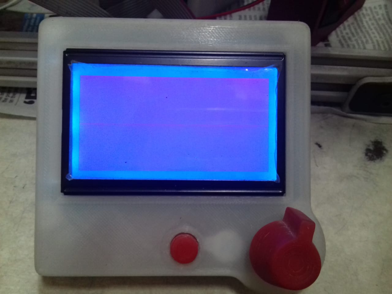
But, I did't show anything in my display.
I need Help.
Find the attached firmware source code and picture of display.
sorry for my english,
I have Einsy rambo.
and I upload the firmware from [https://github.com/prusa3d/Prusa-Firmware/tree/MK3]
I edit the firmware for Full Graphic smart controller as per nmp1 suggest
// The RepRapDiscount Smart Controller (white PCcool smiley
//#define REPRAP_DISCOUNT_SMART_CONTROLLER
#define REPRAP_DISCOUNT_FULL_GRAPHIC_SMART_CONTROLLER
#define SDSUPPORT
#define LCD_WIDTH 128
#define LCD_HEIGHT 64
But, I did't show anything in my display.
I need Help.
Find the attached firmware source code and picture of display.
|
Re: EinsyRambo April 05, 2019 09:42AM |
Admin Registered: 13 years ago Posts: 6,998 |
Did you install the arduino rambo extensions? They add additional pin definitions to the standard mega2560
Without them the LCD does not work....
See [reprap.org] on how to install it.
Then you select board rambo instead of mega2560 in the arduino IDE
Now recompile it and try it again.
Without them the LCD does not work....
See [reprap.org] on how to install it.
Then you select board rambo instead of mega2560 in the arduino IDE
Now recompile it and try it again.
|
Re: EinsyRambo April 08, 2019 09:22AM |
Registered: 5 years ago Posts: 4 |
|
Re: EinsyRambo April 23, 2019 05:31AM |
Registered: 4 years ago Posts: 1 |
I would like to include the bltouch, but I do not know how to properly wire.
Send a message on this page in case someone could answer it.
[github.com]
Greetings from Spain
Send a message on this page in case someone could answer it.
[github.com]
Greetings from Spain
Sorry, only registered users may post in this forum.