Simplify3D setup?
Posted by Theolodian
|
Re: Simplify3D setup? August 03, 2015 12:38PM |
Registered: 8 years ago Posts: 155 |
Thanks Ian.
After calibration I have R83.75, I suspect that based on bluesign2k's comments above an arm length of 165 and redo calibration including R would be a better fudge until you figure out the geometry. I'll probably also move the outer probe points to 50mm from centre instead of 75 for normal power-on setup. I'm not familiar with Deltas, I don't know what has been done before, but the math involved in modelling the tilt of the head as you get towards the outer edge will take a while to sort out.
So the calibration doesn't take care of a warped bed? Mine is the same as yours. Cast acrylic is better than extruded, but expensive and not perfect. I suppose some sort of glass or ceramic would work as an upgrade if not too fragile. For the price of the kit I'm not fussed.
|
Re: Simplify3D setup? August 03, 2015 02:19PM |
Registered: 10 years ago Posts: 14,672 |
Quote
Theolodian
So the calibration doesn't take care of a warped bed?
Yes it does, to a first-order approximation, which should be good enough on a small machine such as the Fisher. But if the bed is warped, the bottom of your prints won't be flat! Also the XY dimensions may be a little out, but you can compensated for that by adjusting the diagonal rod length parameter.
Edited 2 time(s). Last edit at 08/03/2015 02:21PM by dc42.
Large delta printer [miscsolutions.wordpress.com], E3D tool changer, Robotdigg SCARA printer, Crane Quad and Ormerod
Disclosure: I design Duet electronics and work on RepRapFirmware, [duet3d.com].
|
Re: Simplify3D setup? August 03, 2015 02:24PM |
Registered: 8 years ago Posts: 475 |
Hello,
I should have done that before, but I checked the flatness of my bed, and the center is ~0.25 mm lower than the sides.
I assume that the calibration routine then create a fictive geometry with wrong arm radius, and then the parts which are manufactured does reproduce the shape of the bed. That may also explain inaccurate dimensions of built parts.
The tests I have reported previously (7 points, 6 factors) were seemingly using the real arm length of 160mm, but were reporting an arm radius of 82.7mm.
The difference of 1.7mm on the radius to the theoretical dimension (81) may be explained by the center dip ?
I do not really see what shall be the influence of the bowled bed on the calibration routine.
|
Re: Simplify3D setup? August 03, 2015 03:43PM |
Registered: 8 years ago Posts: 68 |
Uh? If the calibration is incorrect then the head's height may fluctuate as you move around the XY play, but the *only* reasons that the head wouldn't stay level are if there is a fundamental mechanical problem. Ultimately this happens if one or more of the rods is of different length, or if one of the rod mounts is bent or loose. Such a problem cannot be corrected by an software calibration.Quote
Theolodian
The head doesn't stay level as you move away from the centre. I am sure this isn't modeled correctly if at all. Sounds like an arm length of 165 might be a good compromise for now.
Well that's a bit worrying. I don't have the printer here now, but I'll check this tomorrow.Quote
droftarts
Check your bed is actually flat. The Fisher I built, it turns out the acrylic is slightly warped, and I have a dip in the middle of my bed of around 0.3mm - it's visible when I put a flat edge across it. We'll have to work out how common this is, and what's causing it, as obviously it needs to be flat.
Indeed, I completely agree that at the very least, the rod length *should* be set to the length of the rod (160 mm), and in theory, so should the radius if everything is assembled correctly. Assuming the bed is flat and not warped, then further to my previous post I found that setting a rod length of 163 mm resulted in correct XY positioning. I made a simple target that I printed and taped to the bed so I could see X/Y positioning as the calibration was being performed (the pdf is attached if anyone is interested, remember to untick fit to page when printing).Quote
droftarts
The config.g uses the actual lengths, from the design files, EXACTLY as it's modelled!
Having said all that, while X/Y positioning was correct, the probe points still fluctuated sinusoidally going around the circumference of the build area. About 6 months ago I decided to learn Python and as learning exercise I wrote a small program to model the effects of uncorrected error in rod length, endstop height, and delta radius. Unfortunately, what that told me as that while any incorrect parameters effected Z positioning across the plane the most, it also always produces error in X/Y positioning too... so if the plane isn't flat, then there's probably error in X/Y too. Since the Fisher is a pretty solid design, I'm tempted to try a manual calibration just to figure out what's happening.
Are the original CAD files available anywhere? I've found the stl and dxf files on github but no SolidWorks files like the other models.
As dc42 said, yes it can (ish), but you definitely wouldn't want to do this. If the bed is warped then I wouldn't consider doing anything else before it's replaced. The calibration could probably get parameters that would work on even the most warped surface. However, every layer will just be a translated version of the non-flat plane, so it's not just a first layer problem.Quote
Theolodian
So the calibration doesn't take care of a warped bed?
Edited 1 time(s). Last edit at 08/03/2015 03:46PM by bluesign2k.
|
Re: Simplify3D setup? August 03, 2015 03:55PM |
Registered: 8 years ago Posts: 155 |
I'm a pretty technical person. but right now I'm just pleased as punch this thing prints so well. So amazingly good for the money, and a world away from my 6 year old doorstop of a printer - think baked goods 
I don't want anyone including RRP to make more of a deal out of this conversation than necessary. That one G31 change and I am laughing, literally. The rest is interesting but not at all 'required' at this price point IMHO.
I don't want anyone including RRP to make more of a deal out of this conversation than necessary. That one G31 change and I am laughing, literally. The rest is interesting but not at all 'required' at this price point IMHO.
|
Re: Simplify3D setup? August 03, 2015 04:38PM |
Registered: 8 years ago Posts: 68 |
Yeh, 100%. I'm loving this printer as it is, but it bugs me that it's possible to be even better. I have to say, coming from a background of using RAMPS / Marlin I think one of the best things about the printer is the Duet and firmware, it just makes it so easy to test stuff like this while quickly switching back to working settings when you just want to print something. I currently have 2 SD cards, one with working(ish) settings and one that I'm using to do this stuff.Quote
Theolodian
...I don't want anyone including RRP to make more of a deal out of this conversation than necessary. That one G31 change and I am laughing, literally. The rest is interesting but not at all 'required' at this price point IMHO.
Is there an admin that can split this topic as much of this discussion has nothing to do with Simplify3D :s
|
Re: Simplify3D setup? August 03, 2015 06:03PM |
Registered: 10 years ago Posts: 14,672 |
Bringing together the issue with warped acrylic beds in this thread, and the possible heated bed upgrade discussed in another thread, I'm tempted to suggest the following:
1. Ask Davek0974 to produce a laser cut aluminium replica of the acrylic bed, complete with mounting holes for the balls. He did laser cut alu bed support upgrades for the Ormerod 1, which were very successful for those who bought them and laser cut alu arms for the Ormerod 1 and 2.
2. Those who want to can stick a Kapton heater on the back of it, paying due attention to how to power it, avoiding melting the neatby acrylic parts, etc.
3. The bed switch contacts will need rewiring because the plate is conducting. At least 2 Duet inputs will be needed, along with firmware changes. Alternatively, [shameless plug] if there is room on the hot end, fit one of my mini differential IR height sensor boards (as chosen by a major 3D printer parts supplier for their new printer design) on the hot end, and use that instead of the bed switches, see [miscsolutions.wordpress.com]. [/shameless plug].
In fairness to RepRapPro, I expect they will sort out the issue with warped acrylic beds fairly quickly.
Large delta printer [miscsolutions.wordpress.com], E3D tool changer, Robotdigg SCARA printer, Crane Quad and Ormerod
Disclosure: I design Duet electronics and work on RepRapFirmware, [duet3d.com].
|
Re: Simplify3D setup? August 04, 2015 03:29AM |
Registered: 10 years ago Posts: 776 |
Hi all,
I am certain i could create an aluminium bed for this machine, as Dc42 said, they are proving very good on the Ormerod printer.
If there is interest, Is there a link to a dxf anywhere?
Thanks
Dave
Another RS Ormerod Mk1 meets the world
Retired now but I used to make....
CNC Machined Mk1 aluminium bed support plates for the Ormerod
CNC machined X-plates and ribs for Mk1 & Mk2 Ormerods
CNC machined bed support arms for the Mk2 Ormerod.
Dual Hot-End heatsink blocks.
|
Re: Simplify3D setup? August 04, 2015 03:41AM |
Registered: 9 years ago Posts: 395 |
Dc42 is there warping problems in the acrylic? I am following the fisher forum both bacause it is still interesting machine to get and also because of its use of acrylic like the E3D printer I am considering getting.
Edited 1 time(s). Last edit at 08/04/2015 03:42AM by Fpex.
----- Making the world smarter @ www.xetal.eu
----- Helping entrepreneurs @ www.fralke.com
Edited 1 time(s). Last edit at 08/04/2015 03:42AM by Fpex.
----- Making the world smarter @ www.xetal.eu
----- Helping entrepreneurs @ www.fralke.com
|
Re: Simplify3D setup? August 04, 2015 04:14AM |
Registered: 10 years ago Posts: 14,672 |
Quote
Fpex
Dc42 is there warping problems in the acrylic? I am following the fisher forum both bacause it is still interesting machine to get and also because of its use of acrylic like the E3D printer I am considering getting.
There was mention of not-quite-flat acrylic beds earlier in this thread, e.g. [forums.reprap.org]. I suspect it's quite hard to get anything other than float glass or milled aluminium flat enough for an ideal print bed. But let's see what RepRapPro comes up with - bear in mind that the Fisher is still in beta.
Large delta printer [miscsolutions.wordpress.com], E3D tool changer, Robotdigg SCARA printer, Crane Quad and Ormerod
Disclosure: I design Duet electronics and work on RepRapFirmware, [duet3d.com].
|
Re: Simplify3D setup? August 04, 2015 04:17AM |
Registered: 10 years ago Posts: 14,672 |
Quote
Davek0974
Hi all,
I am certain i could create an aluminium bed for this machine, as Dc42 said, they are proving very good on the Ormerod printer.
If there is interest, Is there a link to a dxf anywhere?
Thanks
Dave
I expect it is one of these [github.com]. Bear in mind that if people want to use it without glass on top, it needs to be very flat.
Large delta printer [miscsolutions.wordpress.com], E3D tool changer, Robotdigg SCARA printer, Crane Quad and Ormerod
Disclosure: I design Duet electronics and work on RepRapFirmware, [duet3d.com].
|
Re: Simplify3D setup? August 04, 2015 04:39AM |
Registered: 9 years ago Posts: 395 |
Quote
dc42
Quote
Fpex
Dc42 is there warping problems in the acrylic? I am following the fisher forum both bacause it is still interesting machine to get and also because of its use of acrylic like the E3D printer I am considering getting.
There was mention of not-quite-flat acrylic beds earlier in this thread, e.g. [forums.reprap.org]. I suspect it's quite hard to get anything other than float glass or milled aluminium flat enough for an ideal print bed. But let's see what RepRapPro comes up with - bear in mind that the Fisher is still in beta.
First i néed make sure my ormerod is back working after the most disastrous crash I have ever had (all broke!), then when I see they fix the acrylic rod holes I might okay with one.
----- Making the world smarter @ www.xetal.eu
----- Helping entrepreneurs @ www.fralke.com
|
Re: Simplify3D setup? August 04, 2015 04:56AM |
Registered: 8 years ago Posts: 68 |
I've just had a look at how flat the bed is and I've found something pretty interesting. The top surface of the bed (with the BuildTak layer) is pretty damn flat - with a straight edge going across the diameter there are two areas that I can just about squeeze a piece of 100 um thick paper between the edge and the surface... both of these areas are just off centre.
However, if I do the same on the back side of the bed then it's waaaayyy out! the centre is buldging out hugely such that there's easily 500 um of gap under either end of the straight edge. So in my case, it's not that the plate is warped, but more that the surfaces are not planar. I actually got pretty lucky because while I was assembling the printer I had someone else reading the instructions to me, and as it turned out they neglected to mention which side the BuildTak should be placed. As such , it's actually on the opposite side to the way the instructions said to do it. As is, I think that the build surface I have here is flat enough that the undulations can be fairly safely ignored.
Edited 1 time(s). Last edit at 08/04/2015 09:29AM by bluesign2k.
|
Re: Simplify3D setup? August 04, 2015 04:59AM |
Registered: 8 years ago Posts: 155 |
I had no problems with the acrylic rod holes. Scrape around the edge with a hobby knife and fit carefully.
Remember the bed springs touch the motors. I hope they're earthed, but worth checking if you are going to put an alloy plate on them.
What about putting the metal balls on 3D printed top hats that go through a larger hole in the alloy bed to electrically isolate them? Adds tolerance, but that's what the bed probing is for.
|
Re: Simplify3D setup? August 04, 2015 05:17AM |
Registered: 8 years ago Posts: 38 |
|
Re: Simplify3D setup? August 04, 2015 05:25AM |
Registered: 8 years ago Posts: 38 |
Just put a piece of cork on the top of the motors and rubber stopper with a screw and spring in the middle of the hole if your worried. However, it all has a electrical charge it will still know that you lost connection to the side because the wires will not have completed circuit. You can use Kapton Tape. If this make since.
|
Re: Simplify3D setup? August 04, 2015 05:40AM |
Registered: 12 years ago Posts: 1,611 |
If you have got a bed that is concave, I think the quickest way of getting a good, flat, surface will be to get a 3mm thick, 170mm diameter piece of float glass cut by a local glazier. Tape this to the acrylic bed. You should be able to peel the BuildTak off the acrylic (I've taken mine off and put it back on a number of times, and it still adheres well) and put it on the glass.
As a side note, very few other printer manufacturers guarantee a flat bed, and generally require printing on a 'raft' (a printed scaffold that removes any inaccuracy of the bed).
We're looking at the heated bed options. A water-jet cut aluminium bed, with a silicone heater stuck on the back, looks like a promising solution.
Ian
RepRapPro tech support
|
Re: Simplify3D setup? August 04, 2015 05:43AM |
Registered: 12 years ago Posts: 1,611 |
DXF of bed is here (direct link to download): [raw.githubusercontent.com]
We haven't released the SolidWorks files yet, as they still need tidying up.
Ian
RepRapPro tech support
We haven't released the SolidWorks files yet, as they still need tidying up.
Ian
RepRapPro tech support
|
Re: Simplify3D setup? August 04, 2015 05:49AM |
Registered: 8 years ago Posts: 475 |
A DXF was supplied by RRP for the BED (plan 1204)
attached here:
1204_bed.DXF
I think before starting anything, we shall wait the proposal of RRP. It is still a beta.
The main question is what to do for the already delivered machines. They indicated a first batch of 100 was delivered and they continue to sell it.
As suggested for the electrical insulation, an insulator could easily be done. Printed if there is no intention to have a heat bed, and I think a small wood part could work for people who intend to set a heat bed.
Edited 2 time(s). Last edit at 08/04/2015 05:51AM by PRZ.
|
Re: Simplify3D setup? August 04, 2015 06:52AM |
Registered: 10 years ago Posts: 776 |
Thanks for the DXF's,
If perfect flatness is required without a glass top then aluminium will not work, the only way to this with metal is use steel and have it surface ground, it would be heavier and quite expensive but very flat, off-the-shelf- metal is never flat to the small amounts being measured here.
The offer stands though, or of course any other metal bits that may need cutting
Dave
Another RS Ormerod Mk1 meets the world
Retired now but I used to make....
CNC Machined Mk1 aluminium bed support plates for the Ormerod
CNC machined X-plates and ribs for Mk1 & Mk2 Ormerods
CNC machined bed support arms for the Mk2 Ormerod.
Dual Hot-End heatsink blocks.
|
Re: Simplify3D setup? August 04, 2015 03:14PM |
Registered: 8 years ago Posts: 155 |
Back onto S3D, I've set my outline and solid infill underspeeds to 70% and happier.
On a more general note I am now doing a triple skirt. Fire it up, home, probe bed, and go with no manual extrusion - simples. At some point a large or even burnt bit comes off the nozzle, the triple skirt seems to take care of that for now. Otherwise was going into part.
On a more general note I am now doing a triple skirt. Fire it up, home, probe bed, and go with no manual extrusion - simples. At some point a large or even burnt bit comes off the nozzle, the triple skirt seems to take care of that for now. Otherwise was going into part.
|
Re: Simplify3D setup? August 05, 2015 09:13AM |
Registered: 8 years ago Posts: 68 |
I've spent the morning on this and I believe that I have got it as good as it's going to get. I've printed some calibration parts and the most significant error I got was about 30um over 100mm, and the printing plane now seems to be flat - to the extent that watching it closely while it's doing the first layer I can't visually identify any variation.
Despite the theory being that the rod length in firmware should be the same as the actual rod length, I can't get a dimensionally accurate part doing this. I've taken every arm off and measured it - they're all 160 mm from hole centre to centre. The value I have to enter into the config file to get dimensionally accurate parts is 162.8 mm.
To find the correct value for your machine, print out a 100 mm diameter, 8-armed star calibration piece and measure the length of the arms produced. Calculate the new rod length:
The value should be close to correct but might not be perfect if there are other calibration errors, I don't expect it to be out by more than a few hundred microns.
In my config file, I used the probe offset from the latest SD image from RRP (note that the P value has changed)
I then ran a 10 point, 6 factor calibration a few times until the calibration values from M665 and M666 settled - the file is attached. This should give you a new delta radius for your new arm length. You'll need the latest firmware image (RepRapFirmware-1.09d-dc42.bin) from dc42's github in order to save the X and Y tower angles in M665.
I've changed the start script in my Simplify3D profile to:
setz.g is again just a slightly modified version of the file in the latest SD image from RRP so that the head is nearer the bed:
Aside from that I found that my extruder steps per mm was quite a way off from perfect too. I may have missed it but I haven't seen any mention of how to correct this value in the documentation - a little odd considering beginners are unlikely to know how to do this. I did it simply by removing the Bowden tube from the extruder and cutting the filament flush to the outlet of the extruder body. Then extrude 100 mm and cut it off flush again and measure the length cut. It's just a variation of the method that Rich Horne described in the "Extruder Calibration" of his Slic3r blog. Anyway, my steps per mm turned out to be 135.2 rather than 144.0 from the original image.
Edited 1 time(s). Last edit at 08/05/2015 09:14AM by bluesign2k.
Despite the theory being that the rod length in firmware should be the same as the actual rod length, I can't get a dimensionally accurate part doing this. I've taken every arm off and measured it - they're all 160 mm from hole centre to centre. The value I have to enter into the config file to get dimensionally accurate parts is 162.8 mm.
To find the correct value for your machine, print out a 100 mm diameter, 8-armed star calibration piece and measure the length of the arms produced. Calculate the new rod length:
new_rod_length = (measured_arm_length / intended_arm_length) * current_rod_length
The value should be close to correct but might not be perfect if there are other calibration errors, I don't expect it to be out by more than a few hundred microns.
In my config file, I used the probe offset from the latest SD image from RRP (note that the P value has changed)
G31 X0 Y0 Z-0.1 P200
I then ran a 10 point, 6 factor calibration a few times until the calibration values from M665 and M666 settled - the file is attached. This should give you a new delta radius for your new arm length. You'll need the latest firmware image (RepRapFirmware-1.09d-dc42.bin) from dc42's github in order to save the X and Y tower angles in M665.
I've changed the start script in my Simplify3D profile to:
G28	; home all axes
M83	; relative extruder mode
T0	; select extruder 0
M116	; wait
M98 P/macros/setz.g
setz.g is again just a slightly modified version of the file in the latest SD image from RRP so that the head is nearer the bed:
G1 X0 Y0 Z4 F12000
G30
G1 Z0.2 F12000
G92 Z0
G1 Z4 F12000
Aside from that I found that my extruder steps per mm was quite a way off from perfect too. I may have missed it but I haven't seen any mention of how to correct this value in the documentation - a little odd considering beginners are unlikely to know how to do this. I did it simply by removing the Bowden tube from the extruder and cutting the filament flush to the outlet of the extruder body. Then extrude 100 mm and cut it off flush again and measure the length cut. It's just a variation of the method that Rich Horne described in the "Extruder Calibration" of his Slic3r blog. Anyway, my steps per mm turned out to be 135.2 rather than 144.0 from the original image.
Edited 1 time(s). Last edit at 08/05/2015 09:14AM by bluesign2k.
|
Re: Simplify3D setup? August 05, 2015 09:44AM |
Registered: 8 years ago Posts: 155 |
|
Re: Simplify3D setup? August 05, 2015 09:51AM |
Registered: 8 years ago Posts: 68 |
|
Re: Simplify3D setup? August 05, 2015 10:47AM |
Registered: 12 years ago Posts: 1,611 |
SolidWorks files are now in the github repository, in the 'sw' folder: [github.com]
Ian
RepRapPro tech support
Ian
RepRapPro tech support
|
Re: Simplify3D setup? August 15, 2015 03:37PM |
Registered: 8 years ago Posts: 155 |
OK, after a LOT of prints and very challenging Velleman (curse you blue!) I am getting closer...
I am still running R83.8 and L162.8
I had to slow the retraction speed down to 2500mm/min but increased the distance to 3.5mm.
I am running normal printing speed of 3,600, outlines and solid infill at 60% of that. Extruder motor gets very warm without the top on even at this speed.
I am running first layer at 4% speed and 125% width and height.
Under cooling it is dropping to as low as 40% for layers under 15secs.
Next changes are to add 5mm retraction to the end script, and bed.g to the start script. I seem to be getting a couple missed steps that only show up when you go to print another part and the bed levelling is off.
Edited 1 time(s). Last edit at 08/15/2015 03:40PM by Theolodian.
|
Re: Simplify3D setup? January 18, 2016 04:48PM |
Registered: 8 years ago Posts: 40 |
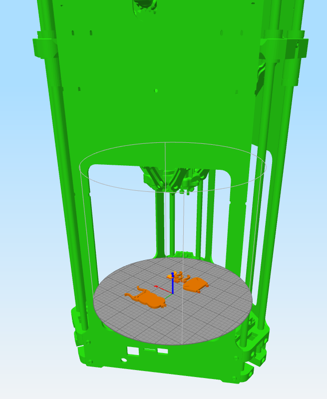
I've taken the full assembly of the Fisher from the official reprap repo, and reorientated it so it can be used inside simplyfy3d as a machine overlay
Stl for s3d import is here
Stl for s3d import is here

Sorry, only registered users may post in this forum.