Printed Arms: print them before the incident!
Posted by PRZ
|
Printed Arms: print them before the incident! September 03, 2015 05:53PM |
Registered: 8 years ago Posts: 475 |
Yesterday, while testing some M codes, I heard a bad noise and duh!, one arm was broken.
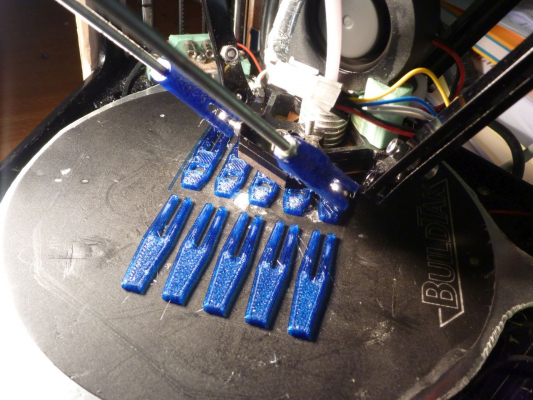
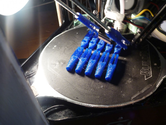
However, I was quite lucky, as I printed the day before some prototypes for printed arms, for future tests.
So, I had no other option than install and test these prototype arms.
Mixed with the original arms, they worked for printing, but I had poor calibration.
Looking closely, you could see that the printed ends are larger at the fork root than the printed end in operation, for tighter spring effect (it nearly doubled the load on the ball)
Anyway, mixing steel and plastic arms is not very good because the thermal expansion is quite different and with my 'light spot' heated bed, I will have temperature size change, so I decided to change all arms, and also to make them longer, for better large diameter printing (which does not work well on Fisher with original arms). I lengthen them from 160 to 170mm. I lost 11mm of height, but the maximum diameter is now workable, with no step loss. However, as arms are thinner, I did not loose maximum diameter height (150mm diameter maximum height is around 83mm, this is limited by the clearance between arms and panels)
In fact, I discover afterward that my poor calibration was due to a hole in the Buildtak at the center calibration point, so my conclusion that this was related to the new arms was quite premature.
Have a look on the BuildTak, which really needs to be retired! The small hole in the middle was the culprit for the faulty calibration, not the new arms.
How are they designed:
They are two printed ends fork-shaped joined by a M3 threaded rod. The length adjustment is done by firmly pressing the internal nut against a thin ring. This allow precise length adjustment (~0,01mm).
As you could see, there is a hole to set a screw pressing the flanges against the ball, but this is not needed, the pinch of the last version being really firm.
They are printed in PETG and I doubt that PLA could be usable, it may broke while setting on balls. ABS is most probably workable.
I initially printed end with cups but they were difficult to fit and the main problem is that it is quite difficult to measure axis to axis length and so, to adjust the arm length. Also, that needs springs.
Compared to the original arms, the holes are shaped to the ball size and the contact area is then much larger. The overall stiffness looks comparable to the original arms, and with calibration spot moved away from holes, I am back to less than 0.01mm difference on 7 points calibration, as before.
The arms are slightly lighter than the original (20g the pair instead of 25 g). the 170mm arm pair weight 22g.
If you decide to lengthen the arms, do not forget to modify and reload the config.g file, then shut down and restart the machine. Do not home before restart!
For 170mm arms, the homed height shall be modified to 171mm.
Threaded M3 rod length is 118mm for 160mm arms, 128mm for 170mm arms. 14mm insertion in simple end, 19mm insertion in nut end. You shall clean well the threaded rod end. Beware not to bend the rods while cutting them if using a manual saw.
Medium washer is required for proper compression adjustment.
Clean the angel hair (I have a lot of angel hair because this is printed with esun PETG which need very high temperature. Lower temperature PETG may be better).
I printed with 0.25mm layers, but you may prefer to print with 0.2mm layers with a standard Fisher (mine have a geared extruder). Slow down speed to 60mm/s. Fill in 70%, honeycomb. This is a quite long print, total may be two hours. One arm set print time is less than half an hour.
You may print a first arm set to check, then the 5 others.
I recommend everyone to have at least one arm set in case of unexpected mechanical incident. (I was quite surprised by the event, and that break instantly!)
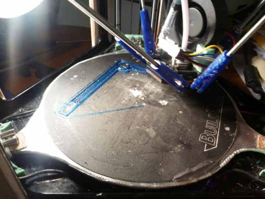
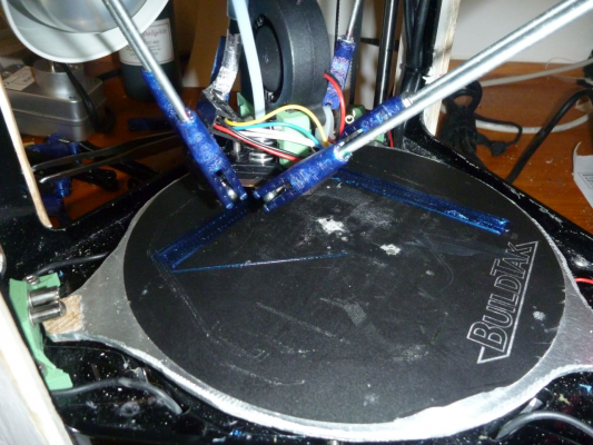
I printed a calibration angle of 100mm, which is near the maximum size (that makes 145 mm on the diagonal with the peripheral loop), and that worked perfectly, without the steps loss that I experienced on larger parts before (I used a travel speed reduced to 180 mm/s).
To fit the ends on balls, push them on the screw, then slide to the ball, that is easier than direct fit.
It is better to set the end with the nut on the carriage for weight reasons, but this is not critical.
[edit] Don't forget to lubricate:
- If printed in ABS, use plastic compatible lubricant. [forums.reprap.org]
- If printed in PETG, you could use any lubricant, as PETG is chemically quite resistant
File with STL and OpenScad in next message :
Arm length measurement will be explained in next message.
Edited 3 time(s). Last edit at 09/03/2015 07:03PM by PRZ.
|
Re: Printed Arms: print them before the incident! September 03, 2015 06:08PM |
Registered: 8 years ago Posts: 475 |
Here, the STL and OpenScad files
OpenScad and STL for 1 set
Fisher_arms1.zip
STL for 5 sets
Fisher_arms5.zip
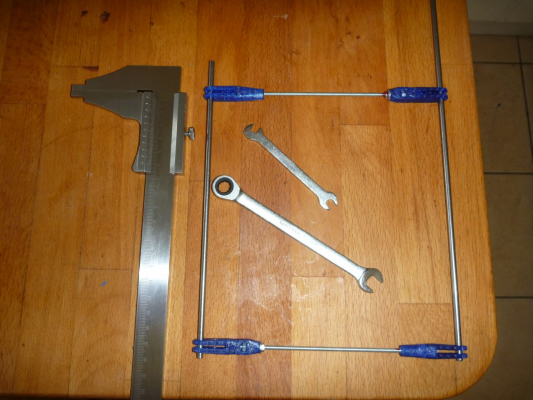
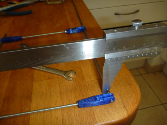
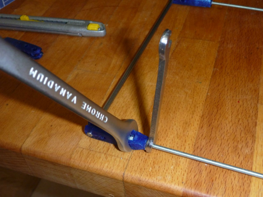
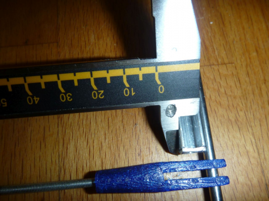
To measured accurately the arm length, you shall use 4mm flush rods, which fits in the end holes
M3 thread pitch is 0.5 mm, so a half turn will move the end by 0.25mm. The ensemble shall be tighten firmly, so the initial length shall be shorter of more than 0.5mm than the desired length. In fact, at initial setup, the nut is not pushed against the ring, so you may need to set the initial length even shorter than that.
The rod is screwed in the simple end. Make a mark to not overtight.
The rod shall not screw in the end with the nut, as this prevent the ring compression to work properly. Clean the hole if needed.
Always measure with another arm set at the end of flush rods for proper alignment. I feel more simple and accurate to measure the inside of the rods than the outside.
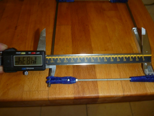
If you only have 150mm caliper, use a calibrated part to compensate the width difference (see photo).
[edit] You shall take into account the rod diameter (4mm), and if needed, the caliper internal measure space - say, with the shown vernier caliper, the measure was : 170-4-10 = 156mm. If you have caliper with crossed internal measure jaws, as the digital caliper shown, the internal measure space is 0.
The arm length is not very critical (you will set it in the config.g) , but all your arms shall have the SAME length, with the best precision you can obtain, and in any case, better than 0.02mm ([edit] that is better done with the vernier caliper that I have used to build my set than with a digital caliper).
[edit] Remember that if the resolution of digital calipers is 0.01mm, their accuracy is only 0.02mm, however their repeatability is probably better than their accuracy.
Edited 2 time(s). Last edit at 09/03/2015 07:25PM by PRZ.
|
Re: Printed Arms: print them before the incident! September 03, 2015 08:58PM |
Registered: 8 years ago Posts: 443 |
Very interesting, I've bought some carbon rods and 6mm RC ball links that I intended to make my new arms from... but I'm still waiting for the ball links to snail mail it here!
Fortunately the Fisher is my second printer so I can easily make these on the Mendel
Yours do have the advantage of being adjustable.... but I may try printing a set of arm ends instead of the ball links, I'm hoping the carbon rods will give me strength and lightness, and be less likely to take on a bend.
One small concern I have is whether the fragile arms provide a sacrificial function to the fisher
RepRapPro Mendel 3 Tricolour
RepRapPro Fisher
-Carbon Arms
-Easy adjust Carriage+effector
-axis stiffness mods
HE3D -600 delta
-Duet 0.8.5
-PanelDue
-DC42 Height probe
-RobotDigg metal components
Simplyfy3D
RS Design Spark CAD
|
Re: Printed Arms: print them before the incident! September 04, 2015 02:31AM |
Registered: 8 years ago Posts: 83 |
|
Re: Printed Arms: print them before the incident! September 04, 2015 04:32AM |
Registered: 8 years ago Posts: 83 |
I printed one to try with PLA (no other filament available - but PETG is in command)
The arms did not cracked when putting the ball in.
In contrario, I think the ball is too tight, the movements are not so easy
A suggestion to set the ball easily, make a small gorge from side to hole to guide the ball and have more space to push it (maybe not possible due to small size of the rod end arms)
|
Re: Printed Arms: print them before the incident! September 04, 2015 05:38AM |
Registered: 8 years ago Posts: 475 |
If using PLA, the pressure load is a bit more than double that with PETG, directly related to the the material stiffness. In fact, for PLA, you may need my first version, but it is cancelled. I can redo something adapted to PLA by thinning the fork root by 20/21%. Don't forget to lubricate. However, I will not test as my machine is conditioned for PETG (no part cooling) and I never use PLA. I will chamfer sides to help insertion, which I think may have been quite hard in PLA !
|
Re: Printed Arms: print them before the incident! September 04, 2015 05:44AM |
Registered: 8 years ago Posts: 83 |
Quote
PRZ
If using PLA, the pressure load is a bit more than double that with PETG, directly related to the the material stiffness. In fact, for PLA, you may need my first version, but it is cancelled. I can redo something adapted to PLA by thinning the fork root by 20/21%. Don't forget to lubricate. However, I will not test as my machine is conditioned for PETG (no part cooling) and I never use PLA. I will chamfer sides to help insertion, which I think may have been quite hard in PLA !
Don't take too much time, I'll make the adaptations by myself and experiment it, thanks for the advices
|
Re: Printed Arms: print them before the incident! September 04, 2015 06:12AM |
Registered: 8 years ago Posts: 475 |
Ok, here is a revised OpenScad program for the end. No lib (use the one sent in former message) . Not tested !
To validate the PLA option, set the variable isPLA to true, that will thin the stuff.
To make the number of copies needed, define the variable 'sets'
I added a gouge to help insertion.
Fisher_arms.scad
Pierre
- Safety [reprap.org]
- Embedded help system for Duet and RepRap Firmware [forums.reprap.org]
- Enclosed delta printers Lily [rouzeau.net] and Lily Big [rouzeau.net]
- OpenScad delta printer simulator [github.com]
- 3D printing on my site [www.rouzeau.net]
|
Re: Printed Arms: print them before the incident! September 04, 2015 06:37AM |
Registered: 8 years ago Posts: 83 |
|
Re: Printed Arms: print them before the incident! September 04, 2015 06:40AM |
Registered: 8 years ago Posts: 475 |
I pushed the revised program on GitHub, that will be easier to see the modifications:
[github.com]
Edited 1 time(s). Last edit at 09/04/2015 06:41AM by PRZ.
Pierre
- Safety [reprap.org]
- Embedded help system for Duet and RepRap Firmware [forums.reprap.org]
- Enclosed delta printers Lily [rouzeau.net] and Lily Big [rouzeau.net]
- OpenScad delta printer simulator [github.com]
- 3D printing on my site [www.rouzeau.net]
|
Re: Printed Arms: print them before the incident! September 04, 2015 07:10AM |
Registered: 8 years ago Posts: 475 |
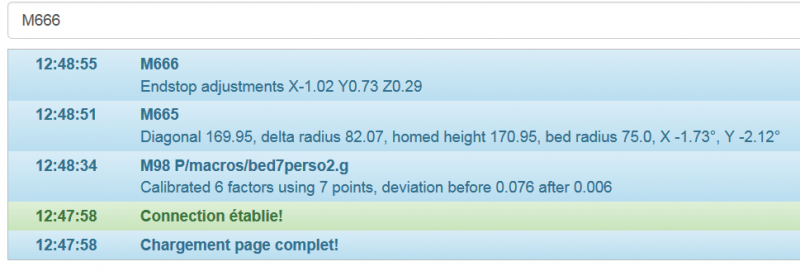
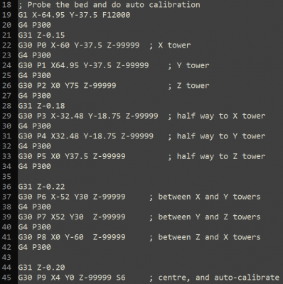
7 points calibration, direct from start. This is with my ravaged Buildtak !
below 0.01 is normal, that was the same before changing the arms. I even get sometimes 0 (I got it one time with the new arms)
You see also the new parameters.
With properly defined switch offset and other parameters, I am normally below 0.2 before calibration. Here that was a bit exceptional.
What is the trick ?
- properly tensioned belts (not too much, however, that increase friction)
- lower bed spring pressure - that is due to the change to aluminium bed
That gives a quite low offset difference between center and near column probe points. I set 0.05.
But the trick is that you shall take into account the intermediate offset for the half-way probe points.
so I set 0.03 difference for the halfway offset and 0.05 for the centre probe offset.
Note that the probe points are slightly moved to take into account the poor state of the buildtak.
[edit] I also reduced the probe test clearance to 2mm instead of 4, which reduce calibration time.
For good arm length measurement, my 40 years old vernier caliper rules !
Edited 1 time(s). Last edit at 09/04/2015 07:12AM by PRZ.
|
Re: Printed Arms: print them before the incident! September 04, 2015 07:17AM |
Registered: 8 years ago Posts: 443 |
|
Re: Printed Arms: print them before the incident! September 04, 2015 08:29AM |
Registered: 8 years ago Posts: 475 |
[EDIT : wrong calibration routine, see next post]
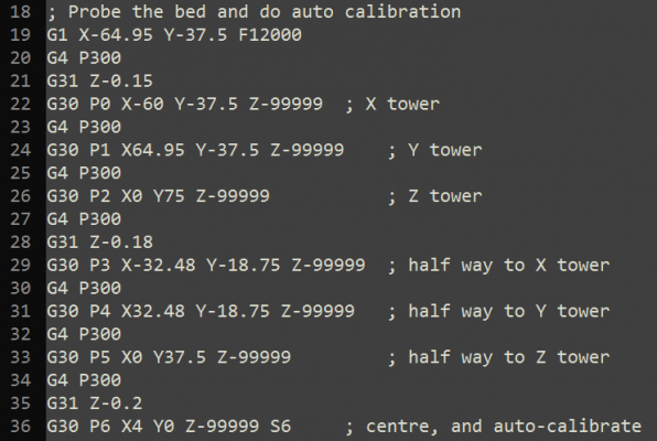
I have taken the 3 other probe points from your post, and the results are less brilliant, while they are relatively constant.
However, while probing 10 points, the message still say this is a 7 points calibration, so I don't know if it takes the seven last probe or if this is an erroneous message ?
Best result is 0.031, worse 0.037.
Iterating the probe macro always worsen the results, so all the tests are done after restart.
This probing gives less angles on the columns, which I think is more accurate.
Here is the probing sequence. It shall be noted that I obtained the best results with an offset sligthly higher for the inter-column points than for the center point (by 0.01).
Edited 1 time(s). Last edit at 09/04/2015 09:32AM by PRZ.
|
Re: Printed Arms: print them before the incident! September 04, 2015 09:31AM |
Registered: 8 years ago Posts: 475 |
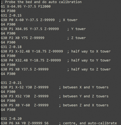
Ok, I found my mistake in the 10 points calibration routine, my probe points were not properly numbered.
The 10 points calibration deviation is remarquably constant at 0.043 (4 different tests).
The corrected calibration routine (Pn numbers , they shall go from P0 to P9)
I slightly increased the offset for inter-columns points at 0.22 (for 0.2 at center), which gives better results
Edited 2 time(s). Last edit at 09/04/2015 10:50AM by PRZ.
|
Re: Printed Arms: print them before the incident! September 04, 2015 11:05AM |
Registered: 8 years ago Posts: 39 |
|
Re: Printed Arms: print them before the incident! September 04, 2015 11:07AM |
Registered: 8 years ago Posts: 83 |
|
Re: Printed Arms: print them before the incident! September 04, 2015 11:15AM |
Registered: 8 years ago Posts: 475 |
There was stl for the PETG/ABS in my first post.
STL file attached for the PLA option (less stiff), but I am not extremely confident of proper operation in PLA. I have not tested.
You may wait the tests of Greg_be on this material. PLA quality is also quite variable.
A solution in case of crack on PLA could be to lengthen the fork (and increase thickness accordingly).
Fisher_arms1setPLA.zip
|
Re: Printed Arms: print them before the incident! September 04, 2015 11:20AM |
Registered: 8 years ago Posts: 39 |
Great! mayby i wasnt specifik enough, but yes it was the PLA version i was looking for! thank you very much! =)Quote
PRZ
There was stl for the PETG/ABS in my first post.
STL file attached for the PLA option (less stiff), but I am not extremely confident of proper operation in PLA. I have not tested.
You may wait the tests of Greg_be on this material. PLA quality is also quite variable.
A solution in case of crack on PLA could be to lengthen the fork (and increase thickness accordingly).
[attachment 61470 Fisher_arms1setPLA.zip]
|
Re: Printed Arms: print them before the incident! September 04, 2015 11:25AM |
Registered: 8 years ago Posts: 475 |
|
Re: Printed Arms: print them before the incident! September 04, 2015 11:30AM |
Registered: 8 years ago Posts: 83 |
|
Re: Printed Arms: print them before the incident! September 05, 2015 06:03AM |
Registered: 8 years ago Posts: 475 |
So I modified the arm end with an introduction channel to help insertion on the balls. Tested on PETG version, it works well.
Here they are :
Fisher_arm_ends.zip
OpenScad code on Github:
[github.com]
Pierre
- Safety [reprap.org]
- Embedded help system for Duet and RepRap Firmware [forums.reprap.org]
- Enclosed delta printers Lily [rouzeau.net] and Lily Big [rouzeau.net]
- OpenScad delta printer simulator [github.com]
- 3D printing on my site [www.rouzeau.net]
|
Re: Printed Arms: print them before the incident! September 05, 2015 06:29AM |
Registered: 8 years ago Posts: 83 |
|
Re: Printed Arms: print them before the incident! September 10, 2015 02:02PM |
Registered: 8 years ago Posts: 83 |
|
Re: Printed Arms: print them before the incident! September 10, 2015 04:10PM |
Registered: 8 years ago Posts: 475 |
|
Re: Printed Arms: print them before the incident! September 27, 2015 02:36PM |
Registered: 8 years ago Posts: 475 |
A note about longer arms and why I increased them:
RRP specifies a maximum usable diameter of 150mm. With the original arms, that will drive to a minimum arm angle of 12.5°, which is very low, so drive to a high carriage speed and acceleration while printing in large diameter. So It is needed to reduce travel speed and may be acceleration to print near maximum diameter.
With arms lengthened by 10mm (170mm instead of 160mm), the height loss is 11mm, but the minimum angle for 150mm diameter becames 23.5°, which divide the carriage speed at 150mm diameter printing by half (tan(12.5°) / tan(23.5°) = 0.51). The carriage speed decrease becames less significant as soon as you reduce the diameter.
You could see the effect on the OpenScad delta simulator :
[github.com]
I updated on GitHub the data of the Fisher with alternatives arm length, and also added the last stl files for the printed arms.
This arm lengthening makes the 150mm diameter really usable, however on a limited height.
The effector diameter travel is limited by the panel opening, which conflict with the arms while effector is going up at maximum diameter.
The 150mm diameter is only usable on approximately 80mm height.
To use this diameter, you shall however take care of clearance with the cables attached to panel and with the effector cable attach.
With 170mm arms, if you route the cables outside the printer (which need to drill panels for cable reentry), there is no longer cable clearance problem and it might be possible to effectively have a usable diameter larger than 150mm (approximately 158 mm), however, I did not test it.
Edited 1 time(s). Last edit at 09/27/2015 02:38PM by PRZ.
Pierre
- Safety [reprap.org]
- Embedded help system for Duet and RepRap Firmware [forums.reprap.org]
- Enclosed delta printers Lily [rouzeau.net] and Lily Big [rouzeau.net]
- OpenScad delta printer simulator [github.com]
- 3D printing on my site [www.rouzeau.net]
|
Re: Printed Arms: print them before the incident! September 27, 2015 08:25PM |
Registered: 8 years ago Posts: 443 |
Its all about compromise really, but the general wisdom on Deltas is the minimum angle should be 20 degrees and this puts the stock Fishers effective working diameter at 140mm not 150mm, and yes increasing the length of the arms will address this.
The problem I have with increasing the length of the arms is that without modifying the frame, you have to choose between 'floorspace' or height.
The problem I have with increasing floor space is that on a Delta not all floor space is equal, if you look at your build plate and draw an imaginary triangle that joins the three balls then the area just inside the triangle and on the buildtack is your prime printing space, and as you move outside the triangle the quality of the printing space gets increasingly worse, the only way of increasing the prime printing space is by re positioning the towers.
By increasing the length of the arms to increase the printing area you are losing 10mm of height from your prime printing space, and gaining a little more poor quality printing space.
The other problem is the cables, as PRZ says to get your full 150mm you need to move them, for this reason I've set the maximum area on my Fisher to 140mm diameter
RepRapPro Mendel 3 Tricolour
RepRapPro Fisher
-Carbon Arms
-Easy adjust Carriage+effector
-axis stiffness mods
HE3D -600 delta
-Duet 0.8.5
-PanelDue
-DC42 Height probe
-RobotDigg metal components
Simplyfy3D
RS Design Spark CAD
|
Re: Printed Arms: print them before the incident! September 28, 2015 02:30PM |
Registered: 8 years ago Posts: 475 |
The only reason for decrease of effector stability on large diameter is precisely the low angle of the 'pushing' arm. The stability outside the triangle decrease not because we are outside it but because the angle of the opposite arms is the lowest.
By choosing an angle higher than the often used 20°, I improved the stability on all the largest diameter areas, and especially the area which is outside the triangle. The penalty in height to use 23.5° instead of 20° was 5mm at the middle and 4mm at the periphery.
That is clearly a question of tradeoffs, but I don't intend to print high parts on the Fisher. And 170mm was a round value ...
Sorry, only registered users may post in this forum.




 Thanks