Advice for distorted prints
Posted by James Lord
|
Advice for distorted prints November 08, 2015 02:27PM |
Registered: 8 years ago Posts: 1 |
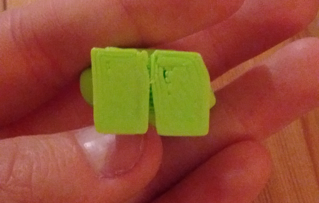
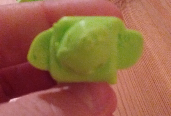
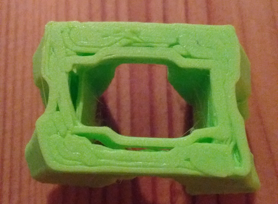
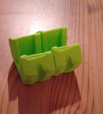
Hi, I have a fisher delta BETA printer and when I print the reprap robot or the replacement idler, the prints are distorted.
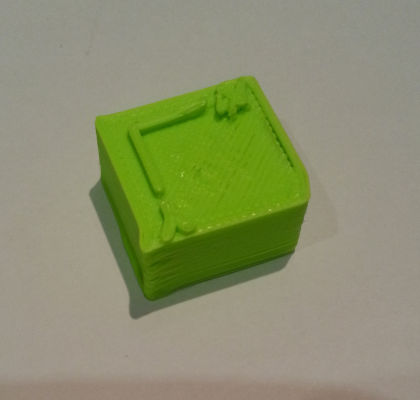
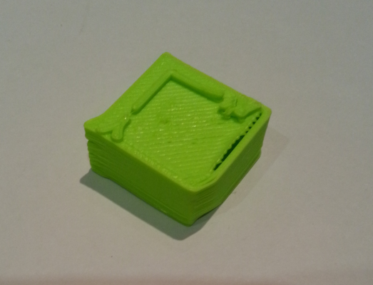
The objects have shifted, if you look at the photos below, you can see the bottom of the idler is not square like a parallelogram. On every print there is the same problem so it's not just a "1 off" if you like. I'm 15 and I have no clue how to describe this issue. lol
Dad and I have checked the printer mechanically and everything feels solid and there is no play.
Could anyone suggest what I could do to troubleshoot and solve this issue. Thanks
|
Re: Advice for distorted prints November 08, 2015 03:32PM |
Registered: 10 years ago Posts: 14,672 |
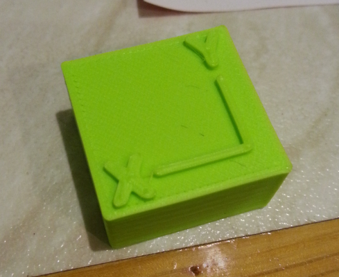
Try printing e.g. a 25mm calibration cube so that all of us can get a better idea of what the problem is.
Large delta printer [miscsolutions.wordpress.com], E3D tool changer, Robotdigg SCARA printer, Crane Quad and Ormerod
Disclosure: I design Duet electronics and work on RepRapFirmware, [duet3d.com].
Large delta printer [miscsolutions.wordpress.com], E3D tool changer, Robotdigg SCARA printer, Crane Quad and Ormerod
Disclosure: I design Duet electronics and work on RepRapFirmware, [duet3d.com].
|
Re: Advice for distorted prints November 08, 2015 06:15PM |
Registered: 8 years ago Posts: 68 |
The first Fisher I assembled the first time had exactly this issue, although not quite to that extent. It happens when one of the balls on either the carriage or effector is loose and is unscrewing when the head is moving. Or, more likely, it also happens if the spacing between the ball pairs on all 3 carriages and the effector aren't equal (and centred).
|
Re: Advice for distorted prints November 11, 2015 02:24PM |
Registered: 8 years ago Posts: 34 |
Quote
dc42
Try printing e.g. a 25mm calibration cube so that all of us can get a better idea of what the problem is.
Thanks - that was a good suggestion. (I'm James' dad and we are both n00bs at this 3D printing lark)
I found a cube which I thought would be helpful: http://www.thingiverse.com/thing:298812.
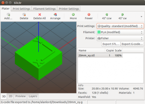
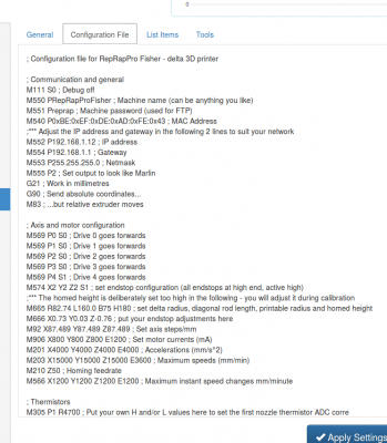
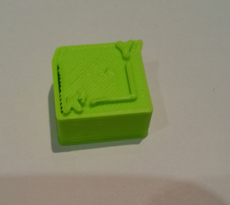
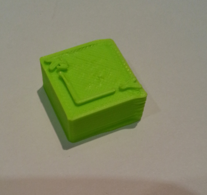
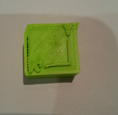
Attached below are the screenshots of:
* the Slic3r programme (we used the standard Fisher profile from the git repo.),
* the config file of the printer
* and a few of prints of the resulting object from various angles.
The calibration cube is a 20mm square box by 10mm high (plus the lettering). My calipers measure the resulting printed object:
X 20.14mm without the protrusion at the top.
Y 19.40mm without the protrusion.
Z ~10.30mm but the edges haven't been cleaned up so it's a bit variable.
Does this help diagnose what the issue might be or even how to track it down perhaps?
Thanks in advance
|
Re: Advice for distorted prints November 11, 2015 04:41PM |
Registered: 8 years ago Posts: 34 |
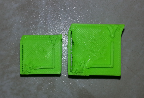
Just for my own curiosty I scaled up the image in Slic3r by 25% to see if the abberation grew linearly along the X and Y axis or if it would stayed proprtionally the same. It stayed exactly the same so to me that is a good thing in that this is a repeatable and predictable problem which should be solvable.
There is the shift to the right at the top of both cubes, the gap in the fill on the left hand Y axis (all the way through the block) and the distortion to the letter X are all basically the same and just scaled up too.
There is the shift to the right at the top of both cubes, the gap in the fill on the left hand Y axis (all the way through the block) and the distortion to the letter X are all basically the same and just scaled up too.
|
Re: Advice for distorted prints November 11, 2015 04:51PM |
Registered: 8 years ago Posts: 34 |
Quote
bluesign2k
The first Fisher I assembled the first time had exactly this issue, although not quite to that extent. It happens when one of the balls on either the carriage or effector is loose and is unscrewing when the head is moving. Or, more likely, it also happens if the spacing between the ball pairs on all 3 carriages and the effector aren't equal (and centred).
Thanks. I have measured the distances between the outside edges of the ball ends* and they are not very consistent but as to how much effect this has I am not sure. Here my measurements:
Effector End:
X 57.16mm
Y 57.50mm
Z 55.94mm
Carriages
X 55.90mm
Y 55.50mm
Z 56.07mm
The balls all seem to be quite tight.
I went back and re-read the Beta instructions and there was no mention of getting the distances bewteen balls and centering accurate so I am unsure of just how much effect this might have.
* I have made carbon fibre arms with the Mugen Seiki ball end joints and they are quite hard to get on and off so I don't really want to dissasemble if I don't have to. I made them accurately using a jig - see an earlier post from me.
|
Re: Advice for distorted prints November 11, 2015 04:54PM |
Registered: 10 years ago Posts: 14,672 |
That shift looks very odd to me. Which firmware are you using? Try 1.09k-dc42 if you are not already using it.
Large delta printer [miscsolutions.wordpress.com], E3D tool changer, Robotdigg SCARA printer, Crane Quad and Ormerod
Disclosure: I design Duet electronics and work on RepRapFirmware, [duet3d.com].
Large delta printer [miscsolutions.wordpress.com], E3D tool changer, Robotdigg SCARA printer, Crane Quad and Ormerod
Disclosure: I design Duet electronics and work on RepRapFirmware, [duet3d.com].
|
Re: Advice for distorted prints November 11, 2015 04:59PM |
Registered: 8 years ago Posts: 34 |
|
Re: Advice for distorted prints November 11, 2015 05:07PM |
Registered: 10 years ago Posts: 14,672 |
There is a bug in 1.09c that can lead to distorted prints on some deltas, although I've never heard of it occurring on a Fisher, nor of it causing the sort of distortion shown in your photos. But upgrading the firmware is easy and eliminates one possible cause of the problem.
Large delta printer [miscsolutions.wordpress.com], E3D tool changer, Robotdigg SCARA printer, Crane Quad and Ormerod
Disclosure: I design Duet electronics and work on RepRapFirmware, [duet3d.com].
Large delta printer [miscsolutions.wordpress.com], E3D tool changer, Robotdigg SCARA printer, Crane Quad and Ormerod
Disclosure: I design Duet electronics and work on RepRapFirmware, [duet3d.com].
|
Re: Advice for distorted prints November 11, 2015 05:16PM |
Registered: 8 years ago Posts: 34 |
|
Re: Advice for distorted prints November 11, 2015 06:40PM |
Registered: 8 years ago Posts: 68 |
I agree with dc42 that the error on those cubes are very weird. Initially I would have said that that it looks like one or more of your arms are catching but the fact that the scaled cube seems to have just scaled the problem, it can't be that. The fact that the is a consistent gap between the perimeter and infill usually suggests a backlash issue (although I've only ever experienced this on Cartesian systems). I'd therefore check are whether your belts are sufficiently tight and whether they are adequately held in the carriages - I've had a few with slightly large holes that allow the tensioned belt to jerk in the hole in carraige as the head moves. This is all assuming that you printed these parts in the centre of the bed
I think I've experienced the bug in the older firmware that Dave mentions too, but I think that bug puts a shift in z for certain geometries (with very small movements)... I assume that was what it was as the problem vanished after I update the FW.
We've assembled (and re-assembled) a fair few of these now and the aim is always 200 um or less variation between all 6, 100 um or less if if I'm after a perfect setup (I have 2 that are that close). If you only intend to print smaller parts in the centre of the bed then maybe try for 500 um. I know its a total pain to re-do these but I promise that it's worth it... even if it takes an hour or more to get them as close as you can.
Oh, and if you have a beta system with acrylic plates for the end effector, it's worth sanding the edges of the acrylic/mdf where the screws for the balls come out of the body to make sure that the plates are flush and level. I also use a washer between the body and nylock to ensure the screws come out straight.
I think I've experienced the bug in the older firmware that Dave mentions too, but I think that bug puts a shift in z for certain geometries (with very small movements)... I assume that was what it was as the problem vanished after I update the FW.
Wow. Yeh, even if this isn't the only source of your problem, a difference of 2 mm isn't going to give you anything other than frustration.Quote
lord_alan
...Here my measurements:
Effector End:
X 57.16mm
Y 57.50mm
Z 55.94mm
Carriages
X 55.90mm
Y 55.50mm
Z 56.07mm
We've assembled (and re-assembled) a fair few of these now and the aim is always 200 um or less variation between all 6, 100 um or less if if I'm after a perfect setup (I have 2 that are that close). If you only intend to print smaller parts in the centre of the bed then maybe try for 500 um. I know its a total pain to re-do these but I promise that it's worth it... even if it takes an hour or more to get them as close as you can.
Oh, and if you have a beta system with acrylic plates for the end effector, it's worth sanding the edges of the acrylic/mdf where the screws for the balls come out of the body to make sure that the plates are flush and level. I also use a washer between the body and nylock to ensure the screws come out straight.
|
Re: Advice for distorted prints November 11, 2015 11:34PM |
Registered: 8 years ago Posts: 443 |
Quote
lord_alan
Effector End:
X 57.16mm
Y 57.50mm
Z 55.94mm
Carriages
X 55.90mm
Y 55.50mm
Z 56.07mm
These figures are not unusual for a stock fisher beta if you look at my build log you will see this
[forums.reprap.org]
Looking at your dims I would reccomend you adjust them as follows
1) tighten up the carriages to try and increase the distance, I would guess that you should be able to make 55.7mm
2) using a file, grinder or dremmel file down the longer screws until they match, when filing you want to take the length off the longer screw, so measure from the ball to the opposite side of the effector on both screws, identify the longest and reduce it, measure frequently util your have the correct distance actoss the bass and the ball to opposite side of carriage dimensions are equal.
3) repeat for the effector.
My setting accuracy is now 0.05mm, but the truth be known anything below 0.2 and the returns are very diminished!
However.... as I originally stated your dimensions are not unusual for a stock fisher Beta and not many people have done the ball matching (certainly very few before I posted my build log), so if this was the problem it would already have been well known.
since you have built Carbon arms make sure you check that the balls are not loose, Blue threadloc is the stuff to use here, make sure you don't use red or purple because these need heat to remove!
An alternative method for ball matching on the fisher is to get your fisher working (or find a friend with a working printer) and print these replacement carriages and effector
[www.thingiverse.com]
You will also need some extra hardware (see the details on Thingiverse), but these allow you to adjust your ball positions without needing to use a file, Ive been using them on mine for a month now and they work great.
RepRapPro Mendel 3 Tricolour
RepRapPro Fisher
-Carbon Arms
-Easy adjust Carriage+effector
-axis stiffness mods
HE3D -600 delta
-Duet 0.8.5
-PanelDue
-DC42 Height probe
-RobotDigg metal components
Simplyfy3D
RS Design Spark CAD
|
Re: Advice for distorted prints November 12, 2015 01:16AM |
Registered: 8 years ago Posts: 443 |
You know, I keep looking back at your pictures, of the calibration cube and the regularity bothers me.....what also bothers me is that the Y looks OK, yet the X looks distorted, plus the separation between infil and boundary...... these are all saying something
If this was on a Cartesian machine then I would be tearing apart the X and Y axes looking for the issue, but, on a delta, if you had a faulty axis then the problem would be unlikely to be as plane consistent as this.
The way the top edge is kicked over and the separation between the infill and edge makes me think there is a problem with acceleration, deceleration and 'exact position stop' (duet firmware may not have an exact position stop feature), I'm guessing that the perimeter was printed anti clockwise..... would be interesting to see a hollow square tube with 5mm wall thickness printed, and see if the kick is in the opposite direction for the inside perimeter..... this would absolutely point to acceleration errors.
Either way, update the firmware.
RepRapPro Mendel 3 Tricolour
RepRapPro Fisher
-Carbon Arms
-Easy adjust Carriage+effector
-axis stiffness mods
HE3D -600 delta
-Duet 0.8.5
-PanelDue
-DC42 Height probe
-RobotDigg metal components
Simplyfy3D
RS Design Spark CAD
|
Re: Advice for distorted prints November 12, 2015 01:18PM |
Registered: 8 years ago Posts: 34 |
Hmmm, following these instructions I have apparently erased the flash but lsusb only reports the:
And when I run the bossac command I get back:
Any suggestions - or have I just bricked my son's Duet?
Bus 003 Device 016: ID 03eb:6124 Atmel Corp. at91sam SAMBA bootloader
And when I run the bossac command I get back:
alanlord@bigyan:~/3DPrinting/RepRapFirmware/Release$ ~/bin/arduino-1.6.1/hardware/tools/bossac -e -w -v -b RepRapFirmware-1.09k-dc42.bin
Auto scan for device failed
Try specifying a serial port with the '-p' option
Any suggestions - or have I just bricked my son's Duet?
|
Re: Advice for distorted prints November 12, 2015 02:20PM |
Registered: 8 years ago Posts: 34 |
|
Re: Advice for distorted prints November 12, 2015 02:23PM |
Registered: 8 years ago Posts: 34 |
Ignore that one. I needed sudo - had no privs to access to the device file - lol.
alanlord@bigyan:~/3DPrinting/RepRapFirmware/Release$ sudo ~/bin/arduino-1.6.1/hardware/tools/bossac --port=ttyACM0 -e -w -v -b RepRapFirmware-1.09k-dc42.bin
Erase flash
Write 229776 bytes to flash
[==============================] 100% (898/898 pages)
Verify 229776 bytes of flash
[==============================] 100% (898/898 pages)
Verify successful
Set boot flash true
alanlord@bigyan:~/3DPrinting/RepRapFirmware/Release$
|
Re: Advice for distorted prints November 12, 2015 02:46PM |
Registered: 8 years ago Posts: 34 |
The firmware update didn't help unfortunately. I started the same 25mm print and the same deflection pattern at the top is there on the first layer so I just cancelled it.
So unless the deflection is embedded in the gcode (is that possible ?) I guess I'd better start dissasembling and checking the ball-ends.
It's funny - but when I do the bed calibration thing (G32) I think I can see a deflection in the path the head takes as it is on it's way to third probe point. I will update once we've checked and re-done the ball-ends.
Thanks for all the advice so far. It's interesting ;-)
|
Re: Advice for distorted prints November 12, 2015 04:59PM |
Registered: 10 years ago Posts: 14,672 |
If that deflection is consistent, then it sounds to me like a mechanical error. If you turn the motors off and try to push the head along that line, do you feel more than the usual amount of resistance when you get to that point?
Large delta printer [miscsolutions.wordpress.com], E3D tool changer, Robotdigg SCARA printer, Crane Quad and Ormerod
Disclosure: I design Duet electronics and work on RepRapFirmware, [duet3d.com].
Large delta printer [miscsolutions.wordpress.com], E3D tool changer, Robotdigg SCARA printer, Crane Quad and Ormerod
Disclosure: I design Duet electronics and work on RepRapFirmware, [duet3d.com].
|
Re: Advice for distorted prints November 12, 2015 05:13PM |
Registered: 8 years ago Posts: 68 |
|
Re: Advice for distorted prints November 12, 2015 06:03PM |
Registered: 8 years ago Posts: 443 |
If this were mechanical the error would probably not be as planar as they are on this and it would not scale with the cube, the error would have an angular relationship that represented the axis with the mechanical error, and the error we are seeing here appears to be Cartesian, which really does point towards software sources.
excessive backlash could explain some of the infill boundary problems, but it doesnt explain the increase in gap with scale....
having discounted firmware, lets look at your slicer...... can you post the first couple of layers of your GCODE file?......
....except a slicer error would not explain the robot which was sliced by RRP!!!!!!!! crap!
The fact that the error scales with the object limits the possibilities a LOT, try printing four cubes in a 2x2 grid do they all come out the same? I expect they will
If this was a backlash or acceleration problem I would not expect to see the fault scale with the scaled up cube......
it is of course possible that this has multiple causes....
Are you printing from pronterface or the Web interface?
If your not using the web interface then try it, if you are using the web interface try starting your print then disconnecting the network cable and let the print complete (or at least get to a point where it displays there are no improvements), this will discount outside influence.
Maybe someone should send you a simple calibration rectangle to print, and if you post your cube gcode file we can have someone else try and print it this would eliminate the slicer question for sure.
Maybe try swapping the motors round, if you move each motor one place clockwise does this change anything?
You can also try rotating the axes on the duet, if you do this move the plugs as follows X-Y Y-Z and Z-X, make sure you move the limit switches the same way, before you print note the orientation on the machine where the faults occur, if after you have rotated plugs the fault stays in the same machine orientation then its a mechanical problem, if it rotates 120 degrees then its software..... if the fault changes then you have both!
Edited 1 time(s). Last edit at 11/12/2015 06:10PM by bgkdavis.
RepRapPro Mendel 3 Tricolour
RepRapPro Fisher
-Carbon Arms
-Easy adjust Carriage+effector
-axis stiffness mods
HE3D -600 delta
-Duet 0.8.5
-PanelDue
-DC42 Height probe
-RobotDigg metal components
Simplyfy3D
RS Design Spark CAD
|
Re: Advice for distorted prints November 12, 2015 08:59PM |
Registered: 10 years ago Posts: 14,672 |
Quote
bgkdavis
... You can also try rotating the axes on the duet, if you do this move the plugs as follows X-Y Y-Z and Z-X, make sure you move the limit switches the same way, before you print note the orientation on the machine where the faults occur, if after you have rotated plugs the fault stays in the same machine orientation then its a mechanical problem, if it rotates 120 degrees then its software..... if the fault changes then you have both!
IMO that is an excellent idea to help diagnose the problem.
Another possibility is to rotate the towers in software. To do this, send M666 with no parameters and read off the XYZ values. Send back an M666 command with 120 added to each of them. Or, since it is a cube, you could try rotating by 90 degrees instead of 120.
Edited 1 time(s). Last edit at 11/12/2015 09:08PM by dc42.
Large delta printer [miscsolutions.wordpress.com], E3D tool changer, Robotdigg SCARA printer, Crane Quad and Ormerod
Disclosure: I design Duet electronics and work on RepRapFirmware, [duet3d.com].
|
Re: Advice for distorted prints November 12, 2015 10:54PM |
Registered: 8 years ago Posts: 443 |
Quote
dc42
Quote
bgkdavis
... You can also try rotating the axes on the duet, if you do this move the plugs as follows X-Y Y-Z and Z-X, make sure you move the limit switches the same way, before you print note the orientation on the machine where the faults occur, if after you have rotated plugs the fault stays in the same machine orientation then its a mechanical problem, if it rotates 120 degrees then its software..... if the fault changes then you have both!
IMO that is an excellent idea to help diagnose the problem.
I've realised my thinking is actually a little flawed, because we are effectively rotating a 90 degree shape 120 degrees so it will be different, to do this test properly you need to first print a 120 degree shape (hexagon or equilateral triangle) note the errors then rotate the axes, this will give by far the easiest to read results.
RepRapPro Mendel 3 Tricolour
RepRapPro Fisher
-Carbon Arms
-Easy adjust Carriage+effector
-axis stiffness mods
HE3D -600 delta
-Duet 0.8.5
-PanelDue
-DC42 Height probe
-RobotDigg metal components
Simplyfy3D
RS Design Spark CAD
|
Re: Advice for distorted prints November 13, 2015 03:14AM |
Registered: 8 years ago Posts: 34 |
Thanks for all the ideas and suggestions... This has been an excellent learning process - for me at least ;-)
After removing 4 of the carbon arms last night I found quite a few issues ...
* Several of the ball-ends had not locked so were freely rotating
* On the X axis of the Effector on one side near the ball end, the middle layer of the three plates had a small piece that was loose! i.e. it had cracked - this meant that the locking nut inside the effector could turn
* After removing the arms one of the pulleys on the motor had some play between it and the flat side of the spindle
Consequently I am now working to get everything tight and locked and as accurate as possible. Before doing any more prints.
If we can get it to a stage where we can print reasonably well then I think I would like to try and print bkgdavis' "easy adjust" effector and carriages, and the re-designed idler and then re-build - if my son lets me of course - lol.
|
Re: Advice for distorted prints November 13, 2015 01:13PM |
Registered: 8 years ago Posts: 34 |
I want to thank everyone for their input.
After fixing the lose ball-ends and the play in the spindle and the cracked effector plate (with Araldite) I didn't bother trying to make all the ball dimensions accurate and thought I'd see how it performed first...
To say I'm pleased is an understatement :-D
I'd better let my son have go for a little while now and then talk him into re-building it - lol...
Sorry, only registered users may post in this forum.
