Mendel90 build
Posted by 41southrap
|
Re: Mendel90 build October 26, 2012 09:05PM |
Registered: 11 years ago Posts: 103 |
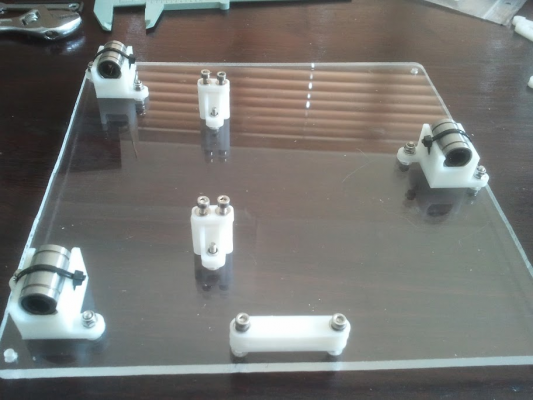
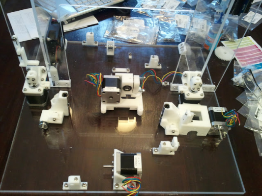
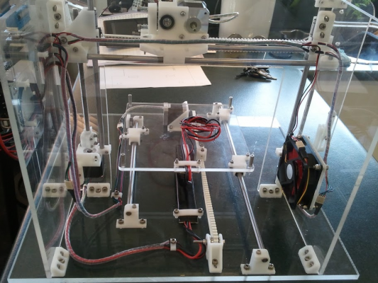
Started the build yesterday, I have the major frame pieces together, along with the bed cooling fan and a temporarily mounted Arduino mega. I've just finished the 'pre-construction' of the y carriage - 'pre' being everything in place and ready for final fitting and adjustments.
This is sure a learning curve, trying to work out the 'what bit goes where' stuff is a challenge at times, but between a bit of logic and Nopheads fantastic part renderings on his web site it doesn't take too long. You need to look at the "big picture" all the time or you'll end up having to take stuff apart to get other parts together. Great fun though!
Edited 1 time(s). Last edit at 10/26/2012 09:07PM by 41southrap.
|
Re: Mendel90 build October 26, 2012 09:13PM |
Registered: 11 years ago Posts: 525 |
Hope not I just had one arrive yesterday from Makerfarm and it has a slight bend on it too. The way I'm mounting it the glass goes straight on top and the heater is directly mounted on the y-carriage so nothing else to help straighten it out.
I also got another hotbed this week, a Helios brand one when I bought an Azteeg X3 and it is twice as thick and dead flat.
_________________________________________________________________________________________
Richmond, New Zealand
Thingiverse ~ YouTube
I also got another hotbed this week, a Helios brand one when I bought an Azteeg X3 and it is twice as thick and dead flat.
_________________________________________________________________________________________
Richmond, New Zealand
Thingiverse ~ YouTube
|
Re: Mendel90 build October 26, 2012 09:21PM |
Registered: 11 years ago Posts: 525 |
Wow, a three bearing carriage. In case you haven't already done this... you should run an 8mm y-axis rod through the pair of bearing holders on the left of that photo and then loosen and re-tighten the bearing holders to let them find the best free movement position.
Is that front clamp for the wiring? Should it be on the other side of the board or how do the wires get to the hot bed?
_________________________________________________________________________________________
Richmond, New Zealand
Thingiverse ~ YouTube
Is that front clamp for the wiring? Should it be on the other side of the board or how do the wires get to the hot bed?
_________________________________________________________________________________________
Richmond, New Zealand
Thingiverse ~ YouTube
|
Re: Mendel90 build October 26, 2012 09:46PM |
Registered: 11 years ago Posts: 103 |
I'm banking on the fact that the bed is clamped to the glass (and that the glass won't warp too  )
)
Thanks for that tip on lining up those bearings too
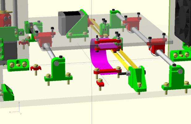
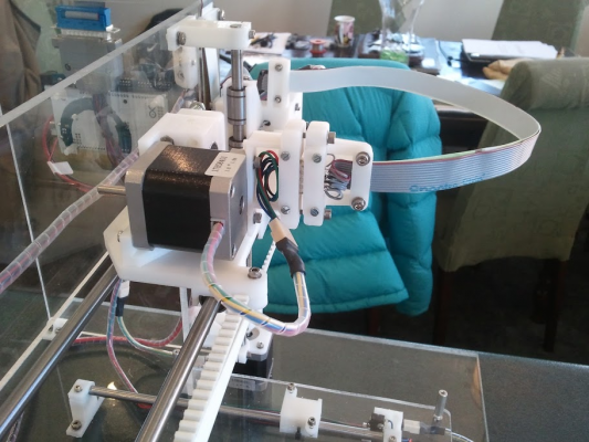
The Nophead design uses a ribbon cable to get power etc to the bed. It looks like the picture below (linked from Nopheads web site) when it's finished (I had the carriage upside down when I took that photo).
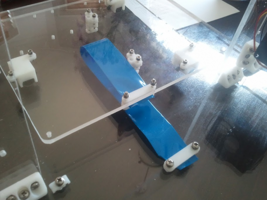
And mocked up using a piece of heat shrink as the ribbon on mine
Edited 2 time(s). Last edit at 10/26/2012 09:50PM by 41southrap.
 )
) Thanks for that tip on lining up those bearings too

The Nophead design uses a ribbon cable to get power etc to the bed. It looks like the picture below (linked from Nopheads web site) when it's finished (I had the carriage upside down when I took that photo).
And mocked up using a piece of heat shrink as the ribbon on mine
Edited 2 time(s). Last edit at 10/26/2012 09:50PM by 41southrap.
|
Re: Mendel90 build October 26, 2012 09:56PM |
Registered: 11 years ago Posts: 525 |
That explains it - I like the ribbon cable idea, like a cable chain.
_________________________________________________________________________________________
Richmond, New Zealand
Thingiverse ~ YouTube
_________________________________________________________________________________________
Richmond, New Zealand
Thingiverse ~ YouTube
|
Re: Mendel90 build October 29, 2012 02:36PM |
Registered: 11 years ago Posts: 103 |
|
Re: Mendel90 build October 31, 2012 06:38PM |
Registered: 11 years ago Posts: 103 |
I now have the new bolts, so that issue is solved.
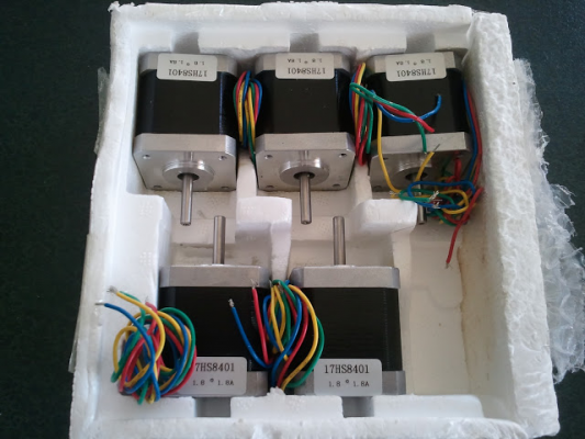
The courier arrived today with the steppers from Aliexpress
The courier arrived today with the steppers from Aliexpress
|
Re: Mendel90 build October 31, 2012 06:42PM |
Registered: 11 years ago Posts: 103 |
|
Re: Mendel90 build November 01, 2012 02:51AM |
Registered: 11 years ago Posts: 103 |
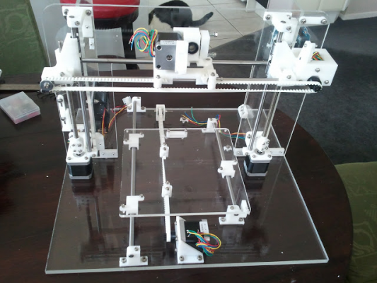
After a major day of building - and 2 trips to Anzor for either stuff I got wrong or they got wrong - all of the major components are coming together. It doesn't look much in the picture 
I haven't yet sourced M8 brass nuts for the lead screws but I talked to the guys at Anzor and picked up some Prolan anti seize grease to see if that works ok with the stainless nuts I have. Changing to brass won't be a big deal if I need to.

I haven't yet sourced M8 brass nuts for the lead screws but I talked to the guys at Anzor and picked up some Prolan anti seize grease to see if that works ok with the stainless nuts I have. Changing to brass won't be a big deal if I need to.
|
Re: Mendel90 build November 01, 2012 03:16AM |
Registered: 11 years ago Posts: 525 |
Good progress, same motors I've been buying too  they work nicely. It will look like a printer soon.
_________________________________________________________________________________________
Richmond, New Zealand
Thingiverse ~ YouTube
 they work nicely. It will look like a printer soon.
_________________________________________________________________________________________
Richmond, New Zealand
Thingiverse ~ YouTube
|
Re: Mendel90 build November 02, 2012 12:11AM |
Registered: 11 years ago Posts: 103 |
One last update for the day
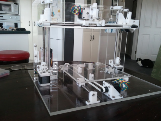
A few things popped out of today's work. Things such as making sure that the pointers on the threaded shaft don't fall under the couplers before you tighten them because then you have to take the whole coupler apart again and put it in the right place! I had a slight issue with the width of my T5 belts which meant that I had to (a) put an extra 4mm washer into the X idler to increase it's width and (b) take to the carriage belt connection points with a scalpel to widen those out a fraction too. Nothing dramatic, maybe a 1/2 to 1mm of material shaved off to allow the clamps to seat properly. Otherwise following the build guide worked well in most cases and common sense filled in the gaps. The result (below) is extremely pleasing indeed - even if I do say so myself - and it's beer o'clock
Tomorrow I need to go to Jaycar and grab my micro switches, as I don't want to destroy the ones that came with the electronics kit (physically that is) which are not quite right for this machine. I'd better go and grab some 2mm glass for the hot bed too. Then it will be on to wiring and ATX PSU modification. It looks like I'll be delayed a short time in completion getting the hot head and hobbed bolt sorted - should have been a bit more proactive on that one
Had to add this shot - it looks kinda cool from this angle
Yup - back working on the kitchen table
Edited 3 time(s). Last edit at 11/02/2012 12:20AM by 41southrap.
A few things popped out of today's work. Things such as making sure that the pointers on the threaded shaft don't fall under the couplers before you tighten them
 because then you have to take the whole coupler apart again and put it in the right place! I had a slight issue with the width of my T5 belts which meant that I had to (a) put an extra 4mm washer into the X idler to increase it's width and (b) take to the carriage belt connection points with a scalpel to widen those out a fraction too. Nothing dramatic, maybe a 1/2 to 1mm of material shaved off to allow the clamps to seat properly. Otherwise following the build guide worked well in most cases and common sense filled in the gaps. The result (below) is extremely pleasing indeed - even if I do say so myself - and it's beer o'clock
Tomorrow I need to go to Jaycar and grab my micro switches, as I don't want to destroy the ones that came with the electronics kit (physically that is) which are not quite right for this machine. I'd better go and grab some 2mm glass for the hot bed too. Then it will be on to wiring and ATX PSU modification. It looks like I'll be delayed a short time in completion getting the hot head and hobbed bolt sorted - should have been a bit more proactive on that one

Had to add this shot - it looks kinda cool from this angle
Yup - back working on the kitchen table

Edited 3 time(s). Last edit at 11/02/2012 12:20AM by 41southrap.
|
Re: Mendel90 build November 02, 2012 01:22AM |
Registered: 11 years ago Posts: 525 |
For the glass just buy a cheap picture frame from the warehouse (credit to NelsonRap) the A4 certificate ones are normally about the right size, cut the end off and you're there.
_________________________________________________________________________________________
Richmond, New Zealand
Thingiverse ~ YouTube
_________________________________________________________________________________________
Richmond, New Zealand
Thingiverse ~ YouTube
|
Re: Mendel90 build November 02, 2012 04:18AM |
Registered: 11 years ago Posts: 54 |
Thats a lovely looking machine!!! I am sure my coffee table would be more than happy with 3d Printing capabilities.. Good work! 
Protoneer.co.nz - Blog - [blog.Protoneer.co.nz]
Protoneer.co.nz - Shop - [shop.Protoneer.co.nz]

Protoneer.co.nz - Blog - [blog.Protoneer.co.nz]
Protoneer.co.nz - Shop - [shop.Protoneer.co.nz]
|
Re: Mendel90 build November 05, 2012 04:18PM |
Registered: 11 years ago Posts: 103 |
Thanks Bert, that OpenBeam is next on my list!
So, not a lot happening on the build over the last couple of days. I've had to email Chris (Nophead) re a couple of things that have cropped up but I think we have sorted those out. The big one was some torsional twisting of the X motor bracket which was causing the T5 belt to run out to the end of the pulley as the carriage moved back and forth. Chris advised me to run the X carriage smooth rods hard up against the motor bracket before tightening them which does seem to have helped. He is also sending me some new pulleys to have a play with. One of the things I "learned" along the way was NOT to use socket head screws for the inside X axis rod clamps - you can't get to them with an allen key without drilling some nice little 3.5mm holes in the gantry! There is a reason Chris specified hex heads for those
Today I've ordered the J-head MK-VB from Brian at Hotends so that won't take long to arrive I hope and I've also been in touch with Vic re his hobbed shafts, some kapton tape and ptfe tubing. I picked up the galss for $4.50 from the Warehouse yesterday too (thanks Wired1) - now I just have to see if my glass cutting skills can cope with chopping it down to size - how hard can it be?
The wiring is causing me a headache, I'm not completely sold on the ribbon cable idea, I don't know why that should be as it will be perfectly capable of doing the job and is a tidy way to do it. I had a complete set of cables supplied with the electronics (including all the plugs for the Ramps board) and really want to use them so everything is "plug and play", so if I stick with the ribbon I may engineer a break out junction box to go from ribbon to wires. Watch this space.
Colin
So, not a lot happening on the build over the last couple of days. I've had to email Chris (Nophead) re a couple of things that have cropped up but I think we have sorted those out. The big one was some torsional twisting of the X motor bracket which was causing the T5 belt to run out to the end of the pulley as the carriage moved back and forth. Chris advised me to run the X carriage smooth rods hard up against the motor bracket before tightening them which does seem to have helped. He is also sending me some new pulleys to have a play with. One of the things I "learned" along the way was NOT to use socket head screws for the inside X axis rod clamps - you can't get to them with an allen key without drilling some nice little 3.5mm holes in the gantry! There is a reason Chris specified hex heads for those

Today I've ordered the J-head MK-VB from Brian at Hotends so that won't take long to arrive I hope and I've also been in touch with Vic re his hobbed shafts, some kapton tape and ptfe tubing. I picked up the galss for $4.50 from the Warehouse yesterday too (thanks Wired1) - now I just have to see if my glass cutting skills can cope with chopping it down to size - how hard can it be?

The wiring is causing me a headache, I'm not completely sold on the ribbon cable idea, I don't know why that should be as it will be perfectly capable of doing the job and is a tidy way to do it. I had a complete set of cables supplied with the electronics (including all the plugs for the Ramps board) and really want to use them so everything is "plug and play", so if I stick with the ribbon I may engineer a break out junction box to go from ribbon to wires. Watch this space.
Colin
|
Re: Mendel90 build November 08, 2012 03:04AM |
Registered: 11 years ago Posts: 54 |
I totally agree on the cable thing. Nothing looks as bad as a badly wired machine.
But one needs to consider that the machine will move and that the wires have maximum
angles they can bend. I have had only one issue with my Printer and it was to do with
the heated beds wires that broke after bending to much in one direction.
Keep us up to date with your build.
Protoneer.co.nz - Blog - [blog.Protoneer.co.nz]
Protoneer.co.nz - Shop - [shop.Protoneer.co.nz]
But one needs to consider that the machine will move and that the wires have maximum
angles they can bend. I have had only one issue with my Printer and it was to do with
the heated beds wires that broke after bending to much in one direction.
Keep us up to date with your build.

Protoneer.co.nz - Blog - [blog.Protoneer.co.nz]
Protoneer.co.nz - Shop - [shop.Protoneer.co.nz]
|
Re: Mendel90 build November 12, 2012 02:48PM |
Registered: 11 years ago Posts: 103 |
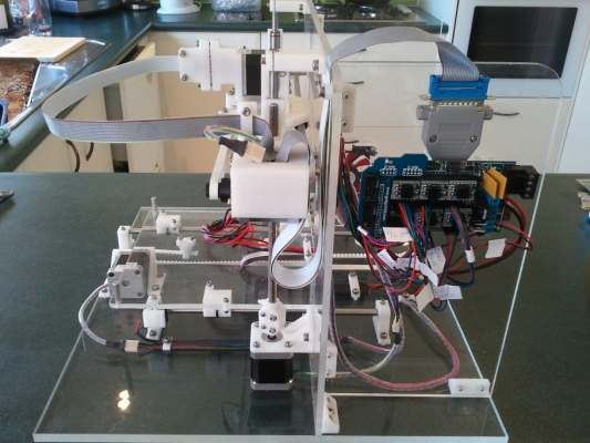
Righto then .... a few days off and a couple of days furious wiring and soldering have yielded a nearly ready to roll Mendel90. I reckon I've spent more hours on the wiring than the mechanics! I stuck with the ribbon for the head stuff but have gone for discreet wires for the bed - still using the "cable chain" idea from Nopheads design. For everything else I've loomed the wiring that came supplied with my electronics kit using clear spiral wrap. I think this goes kinda well with the clear look of the frame and still keeps everything looking tidy. The motors have all got a plug and socket arrangement in case they ever need replacing. The heated bed power wires are a 200 deg c silicon wire that I use in my other hobby (Quad copters) when doing battery wiring. Hobby King silicone wire
I went with a DB25 connector arrangement to transition from ribbon to wires as per the picture. My only hesitation here is hoping that the IDC connections wont give me any trouble. If they do I'll revert to plan B, which will be a small piece of Vero board in a box with soldered joints.
Bed glass - hmmmm - lets just say that it is cheaper in the end to go to Smith and Smith Glass than it is to buy a picture frame from the Warehouse, a glass cutter from Bunnings - and then break the glass Smith and Smith charged me 10 bucks to supply and cut to size a piece of 2mm glass - job done! Today I will be mounting and wiring up the heated bed and perhaps trying to get some movement going. That's the next big leap into the unknown with this project - software. Is there a gui control application for testing? I'm thinking along the lines of being able to move individual motors or put them through a test cycle without breaking things or making the magic smoke escape from small black devices!
Anyways, enjoy the pictures, I'm off to build a heat shield and mount that heated bed.
Oh, another question, what is best to mount the bed thermistor with? Fire cement or did I see glass glue (??) mentioned somewhere? And I understand that it needs to touch the glass when it's mounted?
I went with a DB25 connector arrangement to transition from ribbon to wires as per the picture. My only hesitation here is hoping that the IDC connections wont give me any trouble. If they do I'll revert to plan B, which will be a small piece of Vero board in a box with soldered joints.
Bed glass - hmmmm - lets just say that it is cheaper in the end to go to Smith and Smith Glass than it is to buy a picture frame from the Warehouse, a glass cutter from Bunnings - and then break the glass
 Smith and Smith charged me 10 bucks to supply and cut to size a piece of 2mm glass - job done! Today I will be mounting and wiring up the heated bed and perhaps trying to get some movement going. That's the next big leap into the unknown with this project - software. Is there a gui control application for testing? I'm thinking along the lines of being able to move individual motors or put them through a test cycle without breaking things or making the magic smoke escape from small black devices!
Anyways, enjoy the pictures, I'm off to build a heat shield and mount that heated bed.
Oh, another question, what is best to mount the bed thermistor with? Fire cement or did I see glass glue (??) mentioned somewhere? And I understand that it needs to touch the glass when it's mounted?
|
Re: Mendel90 build November 12, 2012 03:12PM |
Registered: 11 years ago Posts: 72 |
|
Re: Mendel90 build November 12, 2012 04:44PM |
Registered: 11 years ago Posts: 525 |
Yes very tidy, I like the neat approach, looks more professional. I'm a bit nervous about the size of the wires for the hot end. It might be OK but if you have spare cores I would double them up.
For the thermistor I found some glue at Placemakers that can withstand 80 degrees C and I use it for everything. Just check that whatever you buy is good for more than 60 degrees and you'll be fine.
_________________________________________________________________________________________
Richmond, New Zealand
Thingiverse ~ YouTube
|
Re: Mendel90 build November 12, 2012 05:04PM |
Registered: 11 years ago Posts: 103 |
Wires for the hot end are indeed doubled up, Nophead had that in the original wiring design. 
Thanks for the info on the glue, I'll nip down to Bunnings a bit later and have a search.
Decided to get into modifying the ATX power supply unit while I had the soldering iron out. The one I scavenged from work was out of an old IBM server and it has 2 separate 12v busses capable of around 15 amps each. Should do the trick nicely, once I sort through the mess of wires.
|
Re: Mendel90 build November 12, 2012 05:41PM |
Registered: 11 years ago Posts: 525 |
Power supply mod
Edited 2 time(s). Last edit at 11/12/2012 05:44PM by Wired1.
_________________________________________________________________________________________
Richmond, New Zealand
Thingiverse ~ YouTube
Edited 2 time(s). Last edit at 11/12/2012 05:44PM by Wired1.
_________________________________________________________________________________________
Richmond, New Zealand
Thingiverse ~ YouTube
|
Re: Mendel90 build November 13, 2012 05:28PM |
Registered: 11 years ago Posts: 103 |
Thanks for the video - now that I've finished the power supply mods I'll give that a watch  The one I've just done ended up having 3 sense wires, one for each of the 12, 5 and 3.3 volt rails. Luckily I've modded these before so it wasn't a hassle. Output is a solid 12.2 volts on both sets of wires which is great.
I found some high temp glue at Bunnings - good up to 120 deg C according to the blurb on the back.
 The one I've just done ended up having 3 sense wires, one for each of the 12, 5 and 3.3 volt rails. Luckily I've modded these before so it wasn't a hassle. Output is a solid 12.2 volts on both sets of wires which is great.
I found some high temp glue at Bunnings - good up to 120 deg C according to the blurb on the back.
|
Re: Mendel90 build November 13, 2012 11:39PM |
Registered: 11 years ago Posts: 525 |
Yes that's the one I'm using just couldn't remember the name. Sticks like the proverbial.
_________________________________________________________________________________________
Richmond, New Zealand
Thingiverse ~ YouTube
_________________________________________________________________________________________
Richmond, New Zealand
Thingiverse ~ YouTube
|
Re: Mendel90 build November 14, 2012 01:03AM |
Registered: 11 years ago Posts: 103 |
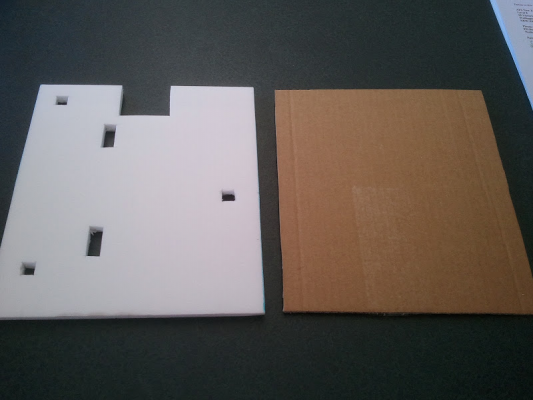
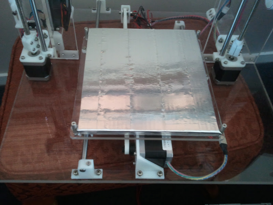
Put together the heat sheild that goes between the heated bed and the acrylic Y bed this afternoon. The foam is some stuff I bought to make foam model aircraft out of some years back and is about 10mm thick. It's nice and stiff so cutting it with a craft knife works and from memory it has good heat characteristics. The cut-outs are just to go over the screws etc on the bed. On top of that goes 3mm of corrugated card from an old box and then metal tape, aka "100 mile an hour" tape.
Mounted on the printer bed
Mounted on the printer bed
|
Re: Mendel90 build November 14, 2012 01:48AM |
Registered: 11 years ago Posts: 1,592 |
|
Re: Mendel90 build November 14, 2012 04:01PM |
Registered: 11 years ago Posts: 103 |
Thanks Waitaki 
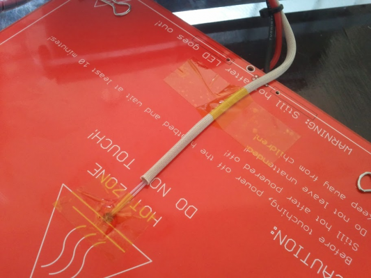
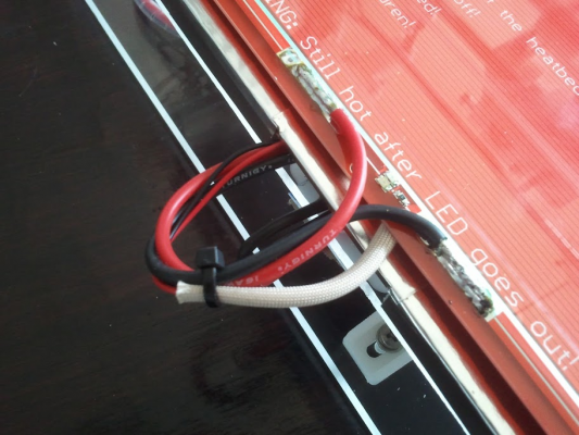
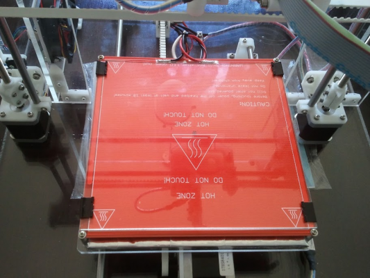
Heated bed wiring done! After reading through everything I could find I went for heated track side up and stuck the thermistor through the hole touching the glass as best I could. It's held in place with a small dob of the high temp glue mentioned a couple of posts back and a piece of Kapton tape (more to keep it in place while the glue dried than anything). The wiring is then enclosed in some of that heat shielding sleeving that you often find in toasters and stoves, I figure if it works for that application it should be ok in this one. The second piece of Kapton is just for wire dressing - can you guess I'm an electronics wiring neat freak? I soldered plenty of wire to the terminals too.
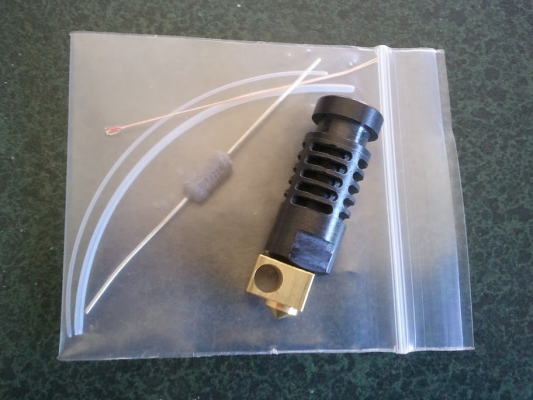
Vik has supplied me with one of his hobbed shafts so I am really just waiting for the J head to arrive to complete the electrical. Next up will be bed leveling and then calibration can start - so much still to do!! I had better tackle getting some firmware onto the Arduino at some stage, that shouldn't be too much problem, that's one part of this project that I AM familiar with. I had better buy some filament at some stage too

Heated bed wiring done! After reading through everything I could find I went for heated track side up and stuck the thermistor through the hole touching the glass as best I could. It's held in place with a small dob of the high temp glue mentioned a couple of posts back and a piece of Kapton tape (more to keep it in place while the glue dried than anything). The wiring is then enclosed in some of that heat shielding sleeving that you often find in toasters and stoves, I figure if it works for that application it should be ok in this one. The second piece of Kapton is just for wire dressing - can you guess I'm an electronics wiring neat freak?
 I soldered plenty of wire to the terminals too.
 Vik has supplied me with one of his hobbed shafts so I am really just waiting for the J head to arrive to complete the electrical. Next up will be bed leveling and then calibration can start - so much still to do!! I had better tackle getting some firmware onto the Arduino at some stage, that shouldn't be too much problem, that's one part of this project that I AM familiar with. I had better buy some filament at some stage too

|
Re: Mendel90 build November 18, 2012 04:13PM |
Registered: 11 years ago Posts: 103 |
There have been quite a few changes made by Nophead to the Mendel90 design, mostly minor things such as changing wiring and connector specs to the head, adding ATX PSU brackets and filament roll holders, a ducted fan around the hot-end, z limit switch placement, removing the spring from the hobbed bolt and using 2 locking nuts etc so if anyone else is building (or thinking about it) then grab the latest files off Github.
I figured out how to drive OpenSCAD enough over the weekend to open up the scad files with exploded view and have a good look around them. What a fantastic way to look at it - I wish I'd done that just a tad earlier in the process!
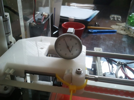
I've borrowed a dial gauge to level the bed with so I'll get on to calibration in the next day or so I hope. I may also look at putting some spring loaded adjustment onto the front 2 bed mounts - not sure on that yet. At the moment it's designed to have small washers used as shims if I read everything correctly. Still waiting for the J-head to arrive, I'm sure it won't be far away - maybe I should have ordered 2 so I have a spare?
|
Re: Mendel90 build November 20, 2012 04:18PM |
Registered: 11 years ago Posts: 103 |
|
Re: Mendel90 build November 22, 2012 02:45PM |
Registered: 11 years ago Posts: 103 |
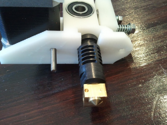
Press fitted the J head into the Wades this morning. It fits snug enough that I can rotate it by hand, but there is no slop or wiggle that I can detect. I used a small G clamp with a piece of poly cutting board between that and the head to press it in, it didn't need too much pressure at all. I see that Nophead now has a small printed part to assist with this part of the assembly 

|
Re: Mendel90 build November 29, 2012 03:41PM |
Registered: 11 years ago Posts: 103 |
It's been a bit of a slow week here in Mendel90 land, so not a lot of progress. I borrowed a dial gauge to do the bed leveling and had a shot at it last night. One thing I have found is that the glass isn't flat. This may be because it's too thin and the uneven heated pcb is managing to warp it a fraction. I added 2 extra clips down the sides and it's better. The trouble is at this stage that (a) I'm not sure what tolerance I can get away with and (b) I'm not 100% sure what I'm reading off the borrowed gauge  It says 0.01mm on the dial face - anyone know if that's per small increment on the face or per number or per rotation? I may have to buy one that I can actually read I think. I hope to power it up over the next couple of days and start the next learning curve of calibration.
 It says 0.01mm on the dial face - anyone know if that's per small increment on the face or per number or per rotation? I may have to buy one that I can actually read I think. I hope to power it up over the next couple of days and start the next learning curve of calibration.
 |
Re: Mendel90 build November 29, 2012 06:11PM |
Registered: 11 years ago Posts: 525 |
I would guess it is 0.01mm per small division. If you have any feeler guages you could run it over the .5mm one and see how far it deflects or use a flat steel ruler on the flat - they are often about 1mm thick.
_________________________________________________________________________________________
Richmond, New Zealand
Thingiverse ~ YouTube
_________________________________________________________________________________________
Richmond, New Zealand
Thingiverse ~ YouTube
Sorry, only registered users may post in this forum.
